Specify the wrong cable type on a purchase order — or let a site electrician substitute “something similar” from the storeroom — and the consequences tend to show up at the worst possible moment: insulation breakdown under load cycling, connector overheating that trips a whole production line, or a voltage drop so severe that variable-frequency drives start faulting. Rework costs alone can run anywhere from a few hundred dollars for a single termination to six figures when conduit is already buried in concrete. The root cause, more often than not, is that the person making the decision didn’t have a clear picture of what the different cable types actually are, how they differ structurally, and which properties make each one right or dangerously wrong for a given application.
Cable types are broadly classified by voltage rating (low-voltage up to 1 kV, medium-voltage up to roughly 35 kV, and high-voltage above that), by conductor material (copper or aluminum), by insulation and jacket compound (PVC, XLPE, EPR, and others), by construction (armored, flexible, screened/shielded), and by application environment (power, control, instrumentation, data, or specialty). Each axis of classification intersects with the others, which is why a single cable description typically references several of these categories at once.
The global wire and cable market was sitting around USD 225 billion in 2023 and is tracking toward USD 300 billion by 2030 — that volume exists because no single cable design covers all uses, and every new installation, grid expansion, or factory build requires someone to make specific, defensible choices across all those classification axes. Low-voltage cables alone account for roughly 45–50% of total installed length worldwide, yet within that category the variation in construction and performance is enormous. Understanding the taxonomy isn’t academic; it’s the difference between a spec that holds up under audit and one that creates warranty disputes two years into a project.
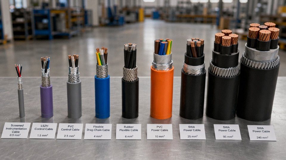
How Cable Construction Defines Every Cable Type: Conductors, Insulation, and Sheathing Explained
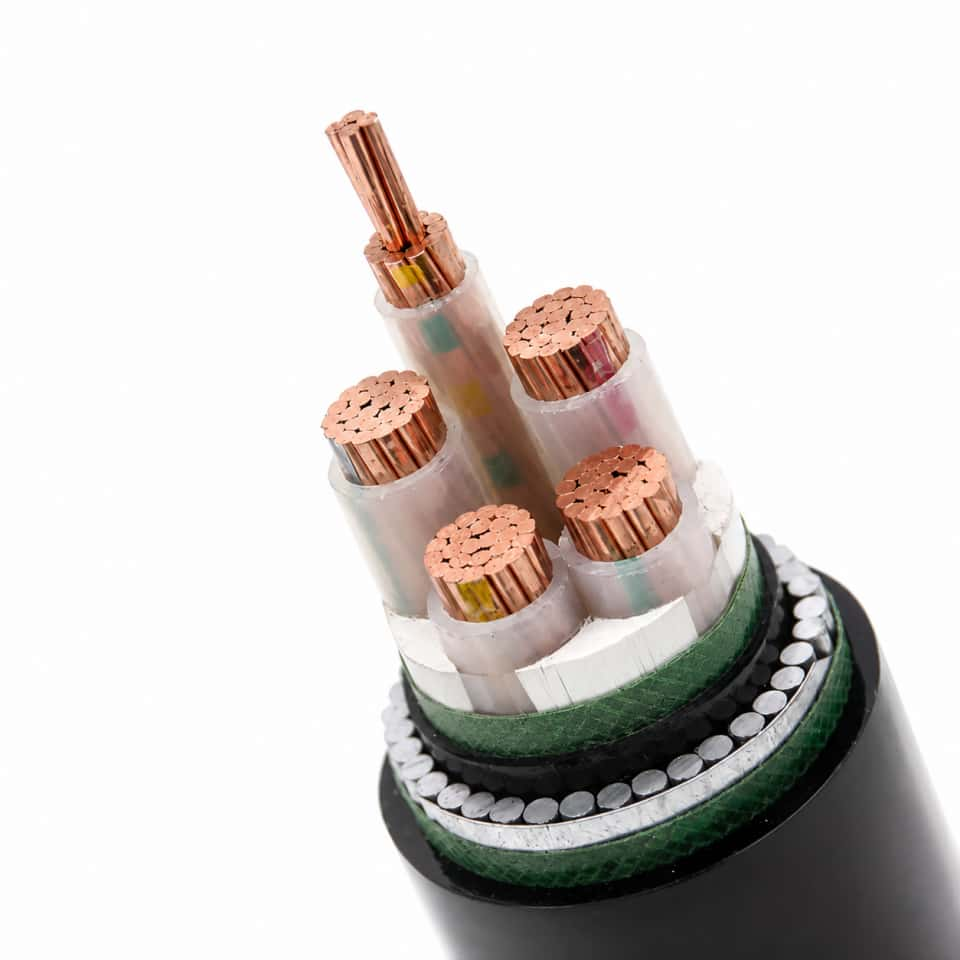
Every cable datasheet is essentially a stack of material decisions — conductor, insulation, shield, armor, sheath — and understanding what each layer does is what separates an engineer who can compare products critically from one who just orders on price. Get one layer wrong and you may not find out until the cable overheats, picks up interference, corrodes from the inside, or fails a fire inspection.
Conductor: the Core Choice That Drives Most of the Cost
Copper dominates control, instrumentation, and building wire — roughly 65% of cable market value globally, and for good reason. It’s dense, solderable, and forgiving. Solid conductors (IEC 60228 Class 1) are straightforward for fixed installations above about 4 mm², but for anything that flexes even occasionally, stranded Class 2 is the minimum. For real flexibility — robotics, drag chains, continuous-flex machinery — you’re looking at Class 5 or Class 6 fine-wire stranding. The difference in flex life between Class 2 and Class 5 in a high-cycle application isn’t marginal; it can be an order of magnitude or more, depending on bend radius and cycle rate.
Aluminum conductors are the practical choice for medium- and high-voltage transmission. They’re 30–40% cheaper per meter than equivalent copper (depending on commodity prices at time of purchase) and substantially lighter, which matters enormously for long overhead runs and large-diameter underground feeders. Plain aluminum work-hardens and is prone to joint failures if terminations aren’t done correctly — AA-8000 series aluminum alloy addresses most of that, with better creep resistance and improved termination reliability, and it’s the standard for most modern aluminum building wire in North American markets.
Tinned copper doesn’t show up on every project, but in marine wiring, offshore instrumentation, or any environment with elevated humidity and aggressive atmospheres, the thin tin coating on each strand is what keeps oxidation from degrading conductivity at terminations over a 20-year service life.
Conductor cross-sections run from 0.5 mm² for signal wiring up to 1,000 mm² or beyond for large power feeders. Size selection is a thermal calculation, not a guess.
Insulation: Temperature Rating Is the Critical Number
PVC insulation is cost-effective and adequate for general building and infrastructure wiring. Standard grade runs to 70°C conductor temperature; 90°C-rated PVC compounds exist but are stiffer and less common. PVC softens and can become brittle at cold temperatures — below about −15°C to −20°C it gets fragile enough to crack during installation, which catches crews off guard on winter construction sites.
XLPE (cross-linked polyethylene) is the workhorse insulation for medium- and high-voltage power cables and increasingly common in low-voltage industrial work. The cross-linking changes the polymer structure fundamentally — it won’t melt or flow above its rated temperature the way thermoplastic PVC will. Continuous rating is 90°C; short-circuit withstand goes to 250°C. That thermal resilience is why XLPE dominates 11 kV–400 kV transmission cable globally.
EPR (ethylene propylene rubber) handles flexibility and low-temperature performance better than XLPE, and it’s particularly well suited for variable-frequency drive cables where high-frequency switching creates capacitive stress. Silicone rubber pushes the temperature envelope further — rated to 180°C continuous, stays flexible down to −60°C, and doesn’t emit toxic gases when burned, which is why it appears in furnace wiring and emergency lighting circuits.
PTFE sits at the extreme end: up to 260°C, chemically inert, thin wall possible, and priced accordingly. You’ll see it in aerospace, analytical equipment, and hot industrial process environments where nothing else survives. It’s not a general-purpose choice.
Shielding: EMI, Capacitance, and the Flexibility Trade-off
Shielding matters the moment you have signal cables running near power cables, variable-frequency drives, or any switching equipment. An aluminum/polyester foil with a drain wire is lightweight, cheap, and provides good high-frequency coverage — standard for instrumentation cables in relatively static runs. Tinned copper braid at 85–95% coverage adds mechanical protection and handles lower-frequency interference better, but adds cost and reduces flexibility slightly. At 96–98% braid coverage the cable is genuinely stiff; that’s acceptable for fixed installation but a problem in continuous-flex applications. Spiral (serve) shields give excellent flexibility and are the right call for drag-chain and robotic cables, but coverage is lower and they’re more susceptible to noise at high flex cycle counts as strands spread.
Shield choice also affects capacitance. Foil shields are closer to the conductor, which increases capacitance per unit length — relevant for long fieldbus runs and high-speed data where signal integrity is tight.
Armoring: Mechanical Protection and Burial
Steel Wire Armour (SWA) is the standard for direct-buried power cables and cables in areas with mechanical exposure — tray edges, conduit transitions, industrial floors. It handles tensile load well and provides solid rodent protection. Steel Tape Armour (STA) gives crush resistance with less tensile strength, suitable for cables that won’t be pulled over long distances.
Where magnetic fields around single-core cables are a concern — large single-core conductors in AC systems — Aluminium Wire Armour (AWA) is specified instead of SWA to avoid induced circulating currents in the armor, which would cause heating and energy loss. This is a point that gets missed surprisingly often.
Burial depth requirements typically start around 500–600 mm for LV cables in cable sand/cover installations, increasing to 900 mm–1,000 mm for MV cables or in areas subject to heavy vehicle loading — check local regulations and the specific project’s ground conditions.
Outer Sheath: Fire Performance and Environmental Resistance
PVC outer sheaths cover the majority of standard installations. They’re economical, UV-resistant in stabilized grades, and broadly chemically resistant. For installations in public spaces, tunnels, rail infrastructure, or any area where smoke and halogen gas release in a fire is a life-safety concern, LSZH (low smoke zero halogen, also written LSOH or LS0H) is specified. Under CPR (Construction Products Regulation) in Europe, cables are classified Euroclass Aca through Fca; LSZH compounds are typically associated with Cca–s1 or better performance, depending on the complete cable construction. Don’t assume an LSZH sheath alone gets you a Euroclass rating — the entire cable, including insulation and filler, is tested as a system.
Polyurethane (PUR) outer sheaths are the choice for cable in contact with oils, hydraulic fluids, and abrasive environments — machine tool wiring, drag chains, food processing. Neoprene (CR) handles both flame exposure and oil contact, and is common in mining, marine, and heavy industrial applications.
LSZH cables produce significantly less toxic smoke than PVC cables in fire conditionsTrue
IEC 60754 and IEC 61034 test data consistently show LSZH compounds emit far lower levels of halogen acid gases and have substantially higher smoke density light transmittance compared to standard PVC compounds during combustion. This is a primary reason LSZH is mandated in confined public spaces.
Construction Layer vs. Typical Installation Environment
| Installation Environment | Conductor Form | Insulation | Shield | Armor | Outer Sheath |
|---|---|---|---|---|---|
| Direct buried (LV/MV power) | Stranded Class 2 or solid | XLPE or PVC | None | SWA or STA | PVC or LSZH |
| Cable tray, industrial plant | Stranded Class 2–4 | XLPE or PVC | Foil or braid (instrumentation) | None or SWA | PVC, LSZH, or PUR |
| Conduit, building interior | Solid or Class 2 | PVC or XLPE | None | None | PVC or LSZH |
| Overhead (self-supporting) | Class 2 aluminum | XLPE or HDPE | None | AWA or none | UV-stabilized PVC |
| Submersible / wet environments | Tinned copper Class 2–4 | EPR or XLPE | Foil + drain | SWA or AWA | Neoprene or LSZH |
| High-flex machinery / drag chain | Class 5–6 fine stranded | EPR or TPE | Spiral shield | None | PUR |
| Tunnel / rail / public building | Stranded Class 2–4 | XLPE or LSZH-insulated | Optional | Optional | LSZH (Cca or better) |
The practical takeaway: no single cable construction is universally optimal. The right stack depends on thermal load, mechanical environment, fire regulation, EMI exposure, and installation method. Working from the conductor outward through each layer — instead of just specifying a generic “power cable” — is what produces a specification that actually survives the service life it’s designed for.
Power Cable Types by Voltage Class: From Low-Voltage Distribution to High-Voltage Transmission
Voltage class is not a label — it is an engineering boundary. Specify the wrong class and you are looking at premature insulation breakdown, failed type tests, voided warranties, and in worst cases a fault that takes down a substation bay. Getting it right starts with understanding what each tier is actually designed to do.
Low-Voltage Power Cables (Up to 1 kV)
This is the workhorse tier. Low-voltage cables — governed by IEC 60502-1 — cover building distribution boards, motor feeders, panel wiring, and virtually every industrial machine connection you will encounter on a plant floor. Cross-sections run from 1.5 mm² for lighting circuits up to 400 mm² for heavy feeder runs, though in practice 95 mm² to 240 mm² handles most industrial motor and transformer feeds.
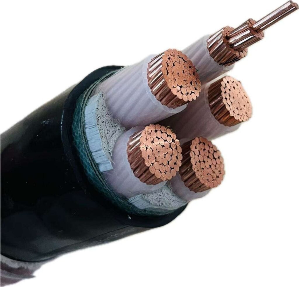
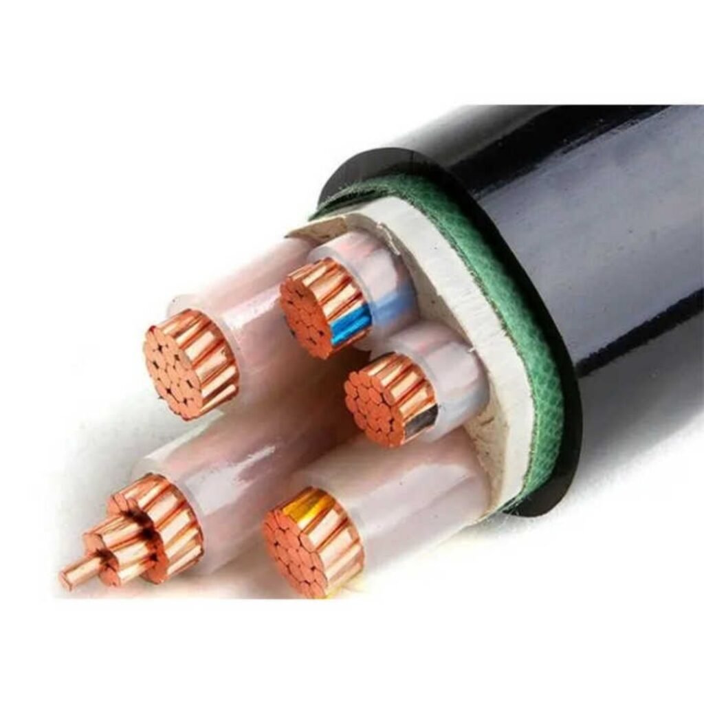
Insulation is almost universally XLPE or PVC. XLPE wins on thermal performance (90°C continuous vs. 70°C for standard PVC) and is the right choice anywhere derating is a concern — long runs in conduit bundles, high-ambient machine rooms. Armoring matters too: SWA (steel wire armored) is standard for direct burial or exposed mechanical risk; unarmored suits trunking and conduit installations where the containment system does the protecting.
A realistic benchmark: a 95 mm² 4-core XLPE/SWA/PVC cable will typically carry roughly 220–240 A when buried at 20°C in standard soil resistivity, derated to around 170–190 A when laying in trefoil on a cable ladder at 40°C ambient. Those numbers shift with grouping, depth, and thermal resistivity of backfill — always run the derating calculation, not just the headline figure from the datasheet.
Medium-Voltage Cables (1 kV–36 kV)
Step into the 6 kV to 36 kV range and the physics changes meaningfully. You need controlled electrical stress at the conductor screen and insulation screen interfaces, which is why semi-conductive screens are not optional — they are the difference between a cable that lasts 30 years and one that fails inside five. IEC 60502-2 governs this tier. Copper wire or tape screens provide the return path and fault current capacity; the right choice depends on fault level at the installation point.
Applications here include utility ring-main networks, wind farm collection circuits (typically 33 kV in most European and Asian projects), and underground mine distribution. Partial discharge testing during factory acceptance is non-negotiable. A PD level above 10 pC at 1.73 × U₀ is a rejection criterion in most serious procurement specs — if your supplier is reluctant to share PD test certificates, that tells you something.
High-Voltage Cables (36 kV–220 kV)
At this level, moisture ingress into the XLPE insulation is a slow killer. Longitudinal and radial water barriers — typically a lead sheath or corrugated aluminum sheath with a PE oversheath — are standard construction for any buried or submarine HV cable. IEC 60840 sets the framework. Factory acceptance tests include tan-delta measurement, partial discharge testing at elevated voltage, and a high-voltage withstand test that the cable must survive intact.
These cables go into underground urban transmission corridors (where overhead lines are politically or physically impossible), offshore wind export connections, and major industrial tie-lines at large petrochemical or steel facilities.
Extra-High-Voltage and Ultra-High-Voltage (220 kV–1,100 kV)
Fewer than a handful of manufacturers globally have demonstrated reliable EHV and UHV cable production. At 500 kV and above, XLPE insulation cleanliness requirements become extreme — any void or contaminant on the order of tens of microns can initiate partial discharge that eventually ruptures the insulation under service voltage. Oil-filled (OF) pipe-type cables remain in service on older installations but new projects predominantly specify XLPE. IEC 62067 is the governing standard.
Jinda has active R&D programs targeting high-voltage cable product lines above 110 kV, consistent with its five-production-base manufacturing infrastructure.True
Stated capability direction consistent with Jinda's published manufacturing scale and international market positioning; buyers should request current type test certificates for specific voltage classes during qualification.
Overhead Bare Conductors: ACSR, AAC, and AAAC
Strictly speaking these are conductors, not cables, but any procurement manager handling transmission projects will deal with them. ACSR (Aluminum Conductor Steel Reinforced) uses steel core strands for tensile strength and aluminum outer strands for current carrying — stranding ratios like 6/1, 26/7, or 54/7 reflect the aluminum-to-steel strand count and determine the sag-tension behavior across a span. AAC (All Aluminum Conductor) and AAAC (All Aluminum Alloy Conductor) sacrifice some tensile strength for better conductivity or corrosion resistance respectively. IEC 61089 covers stranding and mechanical properties. Sag-tension design drives tower spacing and height — getting the conductor selection wrong at this stage ripples into civil and structural costs.
The Cost of Mis-Specification
| Scenario | Consequence | Typical Financial Impact |
|---|---|---|
| Under-voltage rated cable (e.g., 6 kV cable on 11 kV system) | Insulation breakdown within months to years | Replacement + unplanned outage + possible regulatory penalty |
| Over-specified voltage class | Higher upfront cable cost, heavier weight, larger conduit fill | 15–40% cost premium depending on run length |
| Wrong armouring for burial | Mechanical damage, moisture ingress | Early life failure, full cable replacement |
| Missing semi-con screen on MV cable | Stress concentration, premature PD and failure | Warranty void, significant repair cost |
Under-specifying is the dangerous failure mode. Over-specifying mostly costs money — usually somewhere between 15 and 40% more per meter depending on voltage step and construction upgrades. In a 5 km underground distribution project, that delta is real budget. But a cable failure at 11 kV in an urban area means excavation, extended outage, and potential regulatory investigation. The asymmetry argues for conservative specification on voltage class, with cost optimization focused on conductor cross-section and installation method instead.
Control and Instrumentation Cable Types: Keeping Signals Accurate in Industrial Environments
Control and instrumentation cables are not just “small power cables.” That’s a mistake I see on procurement specs more often than it should happen, and it leads to real problems — ground loops, signal drift, nuisance trips, and in VFD-heavy plants, outright communication failures.
What Defines a Control Cable
Control cables are multi-core, typically 4 to 61 cores, with conductor cross-sections running from 0.75 mm² up to about 6 mm². They carry switching commands, relay logic, and motor control centre (MCC) signals — not load current. Insulation is usually PVC to IEC 60227 or XLPE where temperature or chemical resistance demands it. NFPA 79 governs industrial machinery wiring in North American installations and sets specific requirements on conductor colour coding and insulation ratings that don’t always align with IEC practice. Specify clearly which standard applies; a 61-core cable arriving on-site with the wrong colour scheme will stall a commissioning team for days.
Instrumentation Cable Shielding Configurations
This is where it gets granular and where wrong choices cost the most.
Instrumentation cables come in three main shielding arrangements: individually shielded pairs (ISP), overall shield (OS), and the combined individually-and-overall shielded (ISOS) construction. Each serves a different noise rejection purpose.
An ISP cable gives each signal pair its own foil shield and drain wire — critical when you have multiple 4–20 mA loops running in the same cable, because cross-talk between channels will corrupt readings. OS alone works if you’re routing a single signal or a group of identical signals away from interference sources. ISOS gives you both — the individual foil blocks inter-channel cross-talk while the overall braid handles common-mode noise from external fields. For anything near variable-speed drives, large transformers, or power bus bars, ISOS is the only sensible choice.
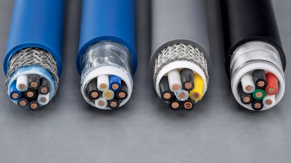
ISOS shielding with both individual foil and overall braid provides better noise rejection than either shield alone in multi-channel instrumentation cables near EMI sources.True
Individual foil shields attenuate capacitively coupled inter-pair cross-talk; the overall braid provides low-impedance return path for externally induced common-mode currents. Combined, they address two independent noise coupling mechanisms that a single shield cannot simultaneously optimise.
Thermocouple Extension and Compensating Cables
Types K, J, T, E, N, R, S, and B per IEC 60584 each require matched alloy conductors — because the thermoelectric voltage depends on the conductor material, not just the temperature difference. Using a standard copper conductor cable to extend a Type K thermocouple introduces a parasitic junction at every termination point, which shows up as a temperature offset that drifts with ambient conditions. Easy to miss during commissioning when the plant is at steady-state temperature; much harder to diagnose six months later during a seasonal swing.
The colour coding trap on international projects is real. IEC 61200-531 and ANSI/ASTM E230 use completely different colours for the same thermocouple type — IEC Type K is green, ANSI is yellow. Mixing cable batches from different regional suppliers on one project has caused exactly this confusion on multi-vendor skid integrations.
4–20 mA Loops, HART, and Capacitance Limits
For analogue loops, capacitance per metre matters. Keep it below roughly 100 pF/m — the actual limit depends on loop length and the HART modem’s frequency requirements (typically 1.2 kHz to 2.4 kHz). Long cable runs with high capacitance attenuate the HART superimposed signal before it reaches the field device, effectively killing digital diagnostics while the 4–20 mA current signal still looks fine on the DCS. A 500-metre run at 120 pF/m is borderline; push to 800 metres and you’ll likely lose HART communication entirely.
Fieldbus Cable Specifications
Fieldbus protocols are unforgiving about cable characteristics because the physical layer is defined by impedance and capacitance targets, not just connector pinout.
| Protocol | Characteristic Impedance | Max Capacitance | Notes |
|---|---|---|---|
| PROFIBUS PA | 100 Ω ±20% | <30 pF/m | Type A cable required for full segment length |
| PROFIBUS DP | 135–165 Ω | <30 pF/m | RS-485 physical layer |
| Foundation Fieldbus H1 | 100 Ω ±20% | <30 pF/m | Same physical layer as PROFIBUS PA |
| Modbus RS-485 | 120 Ω (termination) | <50 pF/m typical | Termination resistors must match cable impedance |
| DeviceNet | 120 Ω | <30 pF/m | Thick vs. thin trunk has separate specs |
Using generic shielded twisted pair instead of specified Type A cable on a PROFIBUS PA segment doesn’t just degrade performance — it can prevent the segment from passing factory acceptance testing. The cable is often the last thing people check, which is backwards.
VFD Environments and EMI-Hardened Cable Design
Variable-frequency drives generate high-frequency common-mode noise that will corrupt unprotected instrumentation signals running in nearby trays. Foil-only shields provide good high-frequency attenuation but have relatively high transfer impedance at lower frequencies. Braid-only shields work well at lower frequencies but let high-frequency noise through. The combination — foil plus braid, with a drain wire sized at least 24 AWG (preferably 20 AWG for longer runs) — covers both ranges.
Grounding strategy is equally important and often botched. Ground the shield at one end only for DC and low-frequency analogue signals to avoid ground loop currents. For high-frequency noise in VFD environments, a hybrid approach — single-point ground at the control room end, with a capacitor to ground at the field end — keeps the shield effective at high frequencies without creating a DC ground loop. That capacitor is a 10 nF, 250 V ceramic type in most industrial installations, though the exact value depends on the specific noise frequency range you’re dealing with.
In practice, routing instrumentation cables in separate trays from VFD power cables, with at least 300–600 mm separation depending on voltage class, reduces the noise problem before it starts. Shielding is the backstop, not the first line of defence.
Data and Communication Cable Types: Structured Cabling, Fibre Optic, and Industrial Ethernet
Data cabling failures are quieter than power faults but often more disruptive — a marginal Cat6 run that worked fine at 25°C starts dropping packets in a hot MDF room, or an unshielded cable routed too close to a 690 V drive feeds noise into a SCADA loop nobody can trace for days. Choosing correctly from the start costs almost nothing extra. Fixing it later costs real money.
Twisted Pair: UTP, STP, FTP, and the Category Ladder
UTP (unshielded twisted pair) dominates office and light commercial structured cabling because it’s cheap, easy to terminate, and adequate in low-EMI environments. Cat5e handles 100 MHz and remains the baseline for 1000BASE-T in spaces where interference isn’t a concern. Cat6 doubles that to 250 MHz, and Cat6A at 500 MHz supports 10GBASE-T up to 100 m — which is why most new data centre horizontal runs and factory IT closets spec Cat6A by default now.
Cat8 (2,000 MHz, 25/40GBASE-T) is physically a different product — tighter pair geometry, mandatory shielding, and segment lengths limited to 30 m or so, making it practical mainly for top-of-rack switch interconnects in high-density data centres, not campus runs.
PoE matters more than people initially think. IEEE 802.3bt (PoE++) delivers up to 90 W per port, and in a bundled 24-pair conduit run that thermal load adds up. Heat dissipation in tightly packed bundles can raise conductor temperature by 10–15°C versus a single free-air cable, which derate current capacity and, over time, accelerate jacket degradation. TIA-568.2-D and ISO/IEC 11801 both address bundle derating, but it’s still routinely ignored in fitout specs.
Shielded variants — F/UTP (foil over bundle), S/FTP (braid plus individual pair foils), U/FTP — are worth the added termination complexity anywhere near variable-frequency drives, welding equipment, or radio transmitters. In practice, an F/UTP Cat6A cable in a PUR jacket handles most light industrial Ethernet installations without the full S/FTP cost premium.
Coaxial Cable: Impedance and Application Split
The 50 Ω vs. 75 Ω distinction is fundamental and non-negotiable. RF transmission and antenna feeds use 50 Ω (RG-58, RG-213, semi-rigid types); CCTV, CATV, and broadband distribution use 75 Ω (RG-6, RG-11, RG-59). Mixing them degrades return loss immediately.
RG-6 is the workhorse for security camera runs — attenuation around 11–13 dB per 100 m at 100 MHz, typically keeping analog HD runs under 200 m before amplification. RG-11, with its larger conductor, drops attenuation to roughly 6–7 dB per 100 m at the same frequency, justifying the cost and stiffness penalty on long trunk runs in large campuses. RG-59 is mostly legacy at this point; its thinner conductor underperforms for anything above 4K video.
Industrial Ethernet: Flex Life and Environmental Rating
Standard Cat6A was not designed for drag chains. Industrial Ethernet cables — PROFINET Type B (flexible) and Type C (highly flexible), EtherCAT-rated cables — are built around stranded conductors, PUR or TPE jackets, and tested flex life ratings typically in the range of 5–20 million bend cycles at a minimum bend radius of 7.5× cable outer diameter. A standard LAN cable routed through a cable track on a robotic arm will develop conductor fatigue within months. The jacket material matters in chemical washdown environments too: PVC gets brittle above 70°C and degrades in contact with cutting oils; PUR doesn’t.
IP67/IP68-rated M12 connectors are the standard mating interface for field-level industrial Ethernet, and the cable jacket OD has to match the connector’s seal range — usually 6–8 mm — so specifying a non-standard jacket diameter creates connector sourcing headaches.
Fibre Optic Types: Single-Mode, Multimode, and Construction
Single-mode (OS1/OS2, 9/125 µm core/cladding) carries one light path with attenuation ≤ 0.4 dB/km at 1310 nm and ≤ 0.2 dB/km at 1550 nm for OS2. That matters on runs over a kilometre — campus backbones, inter-building links, substation to control room. Multimode works at shorter distances: OM3 supports 10G up to roughly 300 m, OM4 up to 400 m, and OM5 (wideband multimode) supports short-wave division multiplexing for 40G/100G in data centre spine applications under 150 m or so. OM1 and OM2 are legacy; don’t spec them for new installations unless replacing an existing run.
OS2 single-mode fibre achieves attenuation ≤ 0.2 dB/km at 1550 nm per IEC 60793-2-50True
This is the standardised OS2 attenuation specification under IEC 60793-2-50 and ITU-T G.652D, commonly verified on cable test certificates.
Fibre construction is a separate decision from fibre type. Loose-tube designs (gel-filled or dry) suit outdoor direct burial and duct installation — the buffer tubes protect against moisture and allow thermal expansion without stressing the glass. Tight-buffered cables suit indoor riser and plenum runs where you’re terminating frequently and don’t want to deal with gel. Ribbon cables pack 12 or more fibres in a flat matrix, enabling mass fusion splicing that cuts jointing time dramatically on high-count backbone installations — relevant to data centre builds where a 144-fibre joint done ribbon-style takes a fraction of the time of individual splices.
Armoured ADSS (all-dielectric self-supporting) cable spans overhead without a messenger wire, which is useful in substations and industrial yards where metallic cables create ground loop or lightning induction risks. One operational warning: hydrogen darkening — where hydrogen generated by cable sheath degradation diffuses into the fibre and raises attenuation over time — is a real issue in oil and gas environments. Specifying hydrogen-scavenging gel or hermetic carbon-coated fibre in those settings isn’t over-engineering; it’s experience talking.
Selection Reference: Data Cable by Application
| Application | Recommended Cable Type | Governing Standard | Max Segment Length |
|---|---|---|---|
| Office/BMS horizontal run | Cat6A U/FTP or F/UTP | TIA-568.2-D / ISO/IEC 11801 | 100 m |
| CCTV trunk run | RG-11 75 Ω coax | — | ~300 m (unamplified) |
| Factory process network (VFD environment) | PROFINET Type B, S/FTP Cat6A PUR | IEC 61918 | 100 m copper |
| Robotic arm / drag chain Ethernet | PROFINET Type C, EtherCAT flex-rated | IEC 61784 | 100 m copper |
| Data centre top-of-rack interconnect | Cat8 S/FTP or OM4 multimode fibre | TIA-568.2-D | 30 m (Cat8) / 400 m (OM4) |
| Campus backbone | OS2 single-mode, loose tube | ISO/IEC 11801 | Up to ~10 km |
| Substation to control room | ADSS single-mode OS2 | IEC 60794-4 | Up to ~4 km span |
The bandwidth-distance relationship in multimode fibre is the one figure most project teams underestimate — it’s not a fixed number but depends on the laser launch condition, connector quality, and splice count. Budget it conservatively.
Specialty and Application-Specific Cable Types: Mining, Marine, Fire Resistant, and Flexible
Standard cables fail quietly in the wrong environment — sometimes with a fault that trips a production line, sometimes with consequences that are far worse. The cable categories below exist precisely because general-purpose designs don’t cut it once you introduce continuous mechanical abuse, salt atmosphere, fire, explosive gases, or ten million flex cycles. Specifying wrong here isn’t a paperwork error; it’s a safety and financial liability.
Mining Trailing Cables
Underground mining cables take punishment that would destroy a standard PVC-insulated power cable within days. Trailing cables for continuous miners and shuttle cars are rubber-sheathed — EPR (ethylene propylene rubber) for insulation and CPE (chlorinated polyethylene) or similar compound for the outer sheath — because rubber absorbs impact and resists tearing against rock edges and shuttle car chassis in ways that thermoplastic compounds simply can’t. Voltage classes typically run 3.3 kV to 11 kV depending on machine size and mine design.
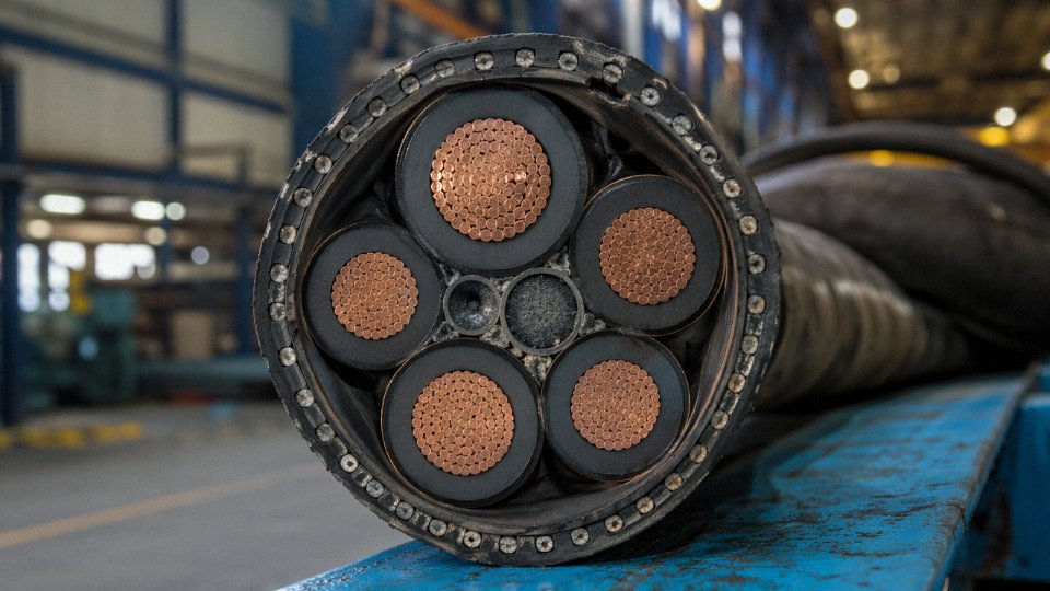
What’s not obvious to specifiers new to mining: these cables carry a dedicated monitor (ground fault protection) core — a small-gauge conductor that enables continuous ground fault monitoring mandated by AS/NZS 2802 and referenced under IEC 60502 Part 4. Losing that monitor function in a wet heading isn’t an acceptable operating condition. Phase-to-phase short-circuit withstand is another hard parameter; the cable has to survive a bolted fault long enough for protection devices to clear it. Jacket durability ratings and minimum bending radius under load are the other two figures procurement teams tend to underspecify until they see premature sheath cracking after a few hundred trailing cycles.
Marine and Offshore Cables
Vessel cabling lives in a hostile combination of salt air, mechanical handling on deck, vibration, and — critically — enclosed spaces where fire gases are lethal. That last point explains why NEK 606 and IEC 60092 compliant cables specify halogen-free sheathing: in a ship’s engine room or accommodation block, hydrogen chloride smoke from burning PVC kills people before the fire does.
Tinned copper conductors are standard practice here, not a premium option. Bare copper corrodes measurably faster in salt atmospheres, and the resulting resistance increase in control circuits causes intermittent faults that are notoriously hard to diagnose. Armoring for mechanical protection against deck handling and cable management hardware is specified at the design stage, not added as an afterthought.
Fire-Resistant and Circuit Integrity Cables
Emergency lighting feeders, fire alarm loops, smoke extract fan supplies, and hospital critical systems all share one requirement: the cable must keep functioning while the building is burning. IEC 60331 defines circuit integrity testing at 750°C to 950°C for defined durations. BS 8519 goes further, specifying system-level performance for enhanced fire protection categories.
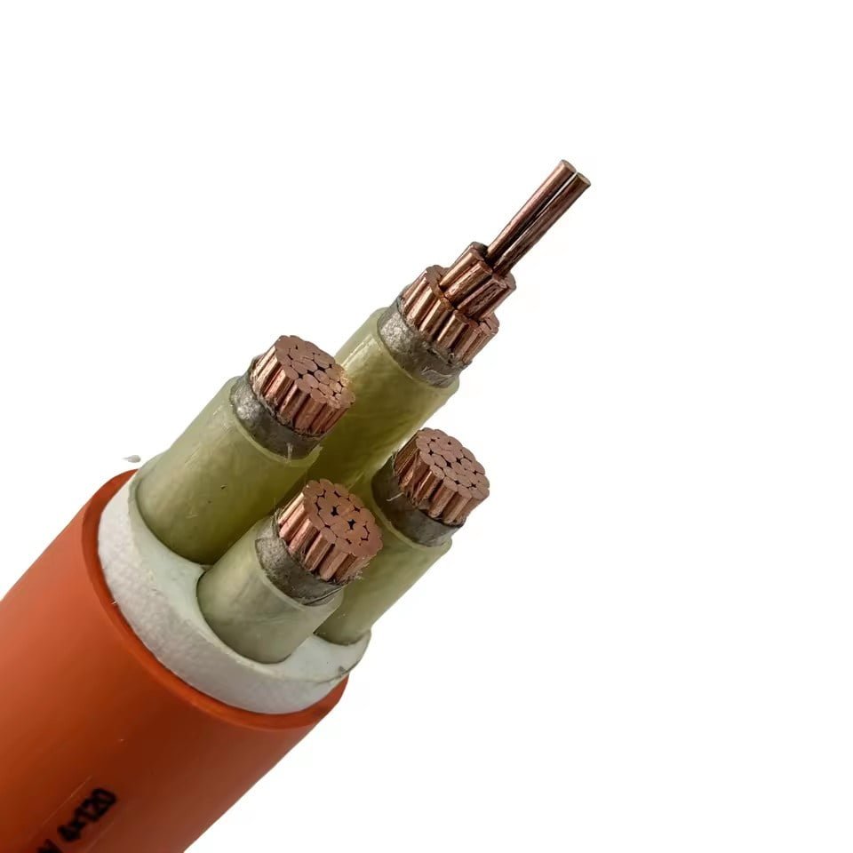
Two main technologies compete here. Mineral insulated copper cable (MICC) uses compressed magnesium oxide insulation in a copper tube — it’s genuinely inert, rated well above 1,000°C, and has been used in nuclear and critical infrastructure for decades. The limitation is rigidity and termination complexity. Ceramic-wrapped fire-resistant XLPE cables offer easier installation and more flexible routing while still achieving 90-minute or 120-minute circuit integrity under IEC 60331; the insulation survives by forming a stable ceramic char rather than by being inherently non-combustible. Choice between them usually comes down to available installation space, bend radius, and termination labor cost.
Flexible and High-Flex Cables
Robot arms, drag chain systems, and rotary indexing machinery impose flex cycles in the millions. Standard fine-stranded Class 5 conductors work loose and break at the strand level; Class 6 ultra-fine stranded conductors per IEC 60228 are what high-flex applications actually need. Insulation material matters equally — silicone rubber handles temperature extremes but can be mechanically delicate; PUR (polyurethane) resists abrasion and oils better in drag chain environments.
Certification programs from Igus, Ölflex, and UL (SEOOW rating) give flex-life data tied to specific bend radius and travel speed combinations. A cable rated for 5 million cycles at 50 mm bend radius may fail at 2 million if the actual installation runs tighter. Always verify against actual machine geometry, not catalog headline figures.
Oil, Gas, and Petrochemical Cables
H₂S resistance is the detail that separates a petrochemical cable from a general industrial one. Standard TPE and PVC compounds are attacked by hydrogen sulfide over time; IEC 60092-351 and specific compound specifications address this. ATEX and IECEx zone classification drives cable selection for explosive atmospheres — a cable suitable for Zone 2 (occasional explosive atmosphere) isn’t automatically appropriate for Zone 1. NEC Article 501 Class I Division 1 vs. Division 2 governs similar decisions in North American jurisdictions. These classifications affect not just the cable but the terminations, glands, and junction boxes as a system.
Cables compliant with IECEx zone classification still require zone-rated glands and termination hardware to maintain explosion-protection integrity.True
IECEx and ATEX certification covers the cable construction, but the complete protection concept depends on all components in the system — a correctly specified cable terminated with an unsuitable gland invalidates the protection level.
Solar and Photovoltaic Cables
PV cables run outdoors, often in direct UV exposure at ambient temperatures that can push 70°C–80°C at cable surface level in full sun, and they operate at DC voltages up to 1,500 V in modern utility-scale systems. TÜV 2PfG 1169 and IEC 62930 define the testing protocol: UV resistance, ozone resistance, temperature range (typically −40°C to +120°C), and double insulation construction that allows single-fault tolerance. Tinned copper conductors again reduce long-term corrosion in outdoor or damp conduit runs. The 1,500 V DC rating is not interchangeable with AC ratings — DC arcs are harder to extinguish, and the insulation system is tested specifically for that fault mode. Specifying a 1 kV AC-rated cable on a 1,500 V DC string because the voltage numbers “seem close” is an error that shows up years later as insulation breakdown or a string-level arc fault.
Wiring Standards and Approval Marks That Govern Cable Type Selection Globally
Anyone who has sourced cable across borders has run into this problem at least once: a product that meets the local standard perfectly gets rejected on-site because the project specification calls for IEC, or because the voltage designation is written differently, or because the fire-performance class stamped on the drum doesn’t map to the CPR class the building contractor is legally required to install. These aren’t paperwork problems. They cause project delays, re-procurement costs, and in some cases structural failures that trigger insurance disputes.
IEC Standards as the Engineering Baseline
The IEC family is the closest thing this industry has to a universal language. IEC 60228 defines conductor classes — Class 1 solid, Class 2 stranded, Class 5 flexible, Class 6 extra-flexible — and any conductor datasheet that can’t be cross-referenced to these classes should immediately raise questions. IEC 60227 covers PVC-insulated cables for fixed and flexible wiring up to 450/750 V. For extruded solid dielectric power cables from 1 kV up to 30 kV, IEC 60502 is the governing document; IEC 60840 and IEC 62067 extend coverage to high-voltage and extra-high-voltage transmission cables respectively. Fire performance is addressed by the IEC 60332 series, which distinguishes between a single-cable vertical flame test and the more demanding bunched-cable test — a difference that matters enormously in cable trays running through occupied buildings.
Jinda aligns its standard product lines to IEC benchmarks as the design baseline, which simplifies certification work for export customers and allows type test data to travel across multiple destination markets without expensive re-testing.
Regional Standards and Where They Diverge
The deviations are more consequential than most procurement teams expect. UK projects operating under BS 7671 (18th Edition) use a different colour code from the IEC harmonised colours — brown for line, blue for neutral is now aligned, but older UK installations still run with red and black, and specifying replacement cable without confirming which era of installation you’re dealing into creates real wiring errors. NEC/NFPA 70 in the United States uses voltage designation conventions that differ from IEC: a cable rated 600/1000 V under IEC is not automatically equivalent to a UL-listed 600 V cable under NEC, because the test methodologies and conductor temperature ratings differ. Australia and New Zealand follow AS/NZS 3000 (the “Wiring Rules”), which mandates specific installation methods that affect conduit fill and minimum cable sizes in ways that IEC tables don’t fully address. GOST standards still govern Russia and much of the CIS market, and GB/T standards apply to the Chinese domestic market — both require separate type testing even when the physical cable construction is nearly identical to an IEC-compliant product.
Certification Marks Buyers Should Require
CE marking under the Construction Products Regulation (CPR) is legally mandatory for cables permanently installed in EU buildings — not optional, not substitutable with a letter of conformity. The CPR fire performance classes run from Eca (minimum, basic contribution to fire) through Dca, Cca, B2ca, B1ca, up to Aca (no contribution to fire). Under EU regulations, cables in escape routes and high-rise buildings typically require a minimum of Cca; critical safety systems may require B2ca or above. Specifying Eca cable in a stairwell installation isn’t just non-compliant — it’s a liability that falls on whoever signed the procurement order.
UL listing (UL 44 for thermoset-insulated, UL 83 for thermoplastic-insulated, UL 1277 for tray cable) is required for North American projects and carries specific ampacity tables. CSA covers the Canadian market. VDE and KEMA-KEUR are widely recognised in European industrial procurement. For Middle East projects, SASO acceptance is often required at Saudi customs. INMETRO is the Brazilian mark. Requiring the actual certificate number — not just a logo on a catalogue — and verifying it against the certification body’s database is standard practice. Logos get copied; certificate numbers don’t lie.
Jinda holds current third-party type test certificates aligned to IEC standards across its main power and control cable product lines.True
Reputable manufacturers of this scale maintain IEC type test certificates through accredited third-party laboratories; buyers should request the specific certificate number and verify it directly with the issuing body.
Halogen-Free and RoHS/REACH Compliance
RoHS restricts ten hazardous substances in electrical equipment sold into the EU; REACH governs the registration and management of chemical substances in products. For cables, practical compliance means confirming that both the insulation compound and the sheath compound have been tested — not just the finished cable assembly. EN 50575 is the product standard underpinning CPR classification and includes halogen content test requirements for halogen-free cable types. Specifying “LSZH” or “halogen-free” without referencing a specific standard and maximum chlorine/bromine content threshold leaves room for supplier interpretation that can result in material variation between production batches.
Third-Party Audits and Certificate Verification
ISO 9001 and ISO 14001 certification tells you something about a manufacturer’s process controls and environmental management, but neither is a substitute for product-specific type test certificates. Type test certificates confirm that a specific cable construction has been tested to a specific standard and passed. Routine test certificates confirm that individual production lengths have been checked against basic parameters — conductor resistance, insulation resistance, voltage withstand — during manufacturing. Both matter. Asking for type test data on routine production without realising the two are different is a procurement error that surfaces later, usually during a third-party site inspection.
The most common compliance error in practice is accepting a supplier’s claim that their cable is “equivalent to” a required standard without requesting the actual test report. Equivalent usually means similar, not tested. On a cross-border project, that difference can cost more than the cable itself.
How to Read a Cable Designation Code and Match It to a Specific Application
A cable designation is a compressed engineering specification. Read it correctly and you can verify a supplier quote in under two minutes. Misread it — or accept a vague description without questioning it — and you may install the wrong product, void your warranty, and spend three times the cable cost in rework.
Decoding the IEC/European Code Structure
The IEC system builds the designation left to right: voltage rating, conductor material, insulation type, inner sheath, armour, outer sheath, then core count and cross-section. Take a real example from a typical industrial substation feeder:
0.6/1 kV Cu XLPE SWA PVC 4×95 mm²
- 0.6/1 kV — rated voltage between conductor and earth / between conductors. This is not a 1 kV cable in the loose sense; both values matter for system earthing configuration.
- Cu — copper conductor. Absence of this symbol in some European notations defaults to copper, but always confirm.
- XLPE — cross-linked polyethylene insulation. Suitable to 90 °C continuous conductor temperature, which directly affects the current-carrying capacity you calculate from IEC 60502-1 tables.
- SWA — steel wire armour. Provides mechanical protection and, depending on how it’s terminated, can serve as a fault return path. Aluminium wire armour (AWA) appears where magnetic losses matter or weight is constrained.
- PVC — outer sheath. Note the sheath compound grade; a standard PVC sheath and a low-smoke zero-halogen (LSZH) sheath are not interchangeable in tunnel or public building installations.
- 4×95 mm² — four cores, each 95 mm² cross-section. On a three-phase plus neutral installation, confirm whether all four cores are equal cross-section or whether a reduced neutral is specified.
Reading NEMA/UL Letter Codes
American designations pack the same information into letter strings, and the logic is worth learning. THHN: thermoplastic insulation (T), heat-resistant to 90 °C (H), second H pushes that to 90 °C in dry locations, N is nylon jacket. THWN-2: adds wet-location rating. XHHW-2: XLPE or similar thermoset insulation, dual-rated 90 °C dry and wet. SHD-GC is a different animal entirely — a shielded mining cable rated to 2,000 V with ground-check conductors; using standard XHHW-2 in a trailing cable application on a continuous miner is a serious safety error.
The “-2” suffix across UL types consistently signals the higher wet-rating revision. It’s a small difference on paper and a meaningful one in a wet process area or outdoor cable tray exposed to seasonal rainfall.
British and European Flexible Control Cable Codes
SY, YY, and CY are the workhorses of European machine-building. SY has a steel wire braid screen and clear PVC outer — you see it everywhere on control panels where EMI shielding and mechanical protection both matter. YY is unscreened, lighter, cheaper, fine for benign environments. CY substitutes a copper braid for the steel, preferred when you need both screening and low contact resistance to earth. NYY and N2XY (XLPE insulated version) are the European direct-burial power cables broadly equivalent to what IEC 60502-1 governs.
| European Code | IEC Functional Equivalent | Typical Use |
|---|---|---|
| NYY | 0.6/1 kV PVC/PVC | Secondary distribution, buried or ducted |
| N2XY | 0.6/1 kV XLPE/PVC | Higher load density feeders |
| SY | Screened flexible control | Panel wiring, machine tools |
| CY | Cu-braid screened flexible | EMI-sensitive automation, VFD panels |
Fibre Optic Designation Logic
OM and OS split multimode from single-mode. Within multimode: OM3 and OM4 support 10GbE to 300 m and 400 m respectively; OM5 extends wideband reach. Single-mode OS2 (ITU-T G.652D) is the standard long-haul choice. G.657A2 is bend-insensitive single-mode — genuinely worth the small premium in buildings where fibre runs through tight conduit bends or distribution frames. The physical construction suffix matters too: loose-tube outdoor cables handle moisture and temperature swing; tight-buffer cables suit indoor pathways and termination-heavy distribution frames. Dual-rated (indoor/outdoor) products exist but check whether the fire performance rating actually meets the indoor standard in your jurisdiction, because sometimes it doesn’t.
Using a Cable Schedule to Catch Errors Before They Reach Site
A cable schedule should carry at minimum: circuit reference, route length, installation method (IEC 60364 reference methods A through F determine derating), design current, voltage drop calculation, and selected cable type with full designation.
Quick worked example: 100 m feeder to a 63 A motor, installed on a perforated tray in ambient 35 °C (reference method E, one derating factor applied). Using IEC 60502-1 tables, 16 mm² Cu XLPE gives roughly 80 A in free air, derated to around 72–76 A depending on grouping — adequate. Voltage drop at 63 A over 100 m on 16 mm² copper runs approximately 7–8 V on a 400 V system, under the 4% threshold. Drop to 10 mm² and you’re borderline or over, depending on power factor. That’s the kind of decision the cable schedule forces you to document before procurement, not after installation.
Red Flags in Supplier Quotations
“XLPE cable, 4-core” is not a specification. It’s a starting point for a conversation you shouldn’t have to have at this stage of a project. Any quotation worth accepting should state voltage class, conductor class (IEC 60228 Class 2 for fixed installation, Class 5 for flexible), nominal insulation thickness, sheath compound type, applicable manufacturing standard, and the test standard the finished cable is submitted to.
Jinda's technical documentation package includes full construction datasheets with conductor class, insulation thickness tolerances, test voltages, and applicable IEC/national standard references for every supplied cable type.True
This is consistent with ISO 9001-managed manufacturing documentation practice and standard customer requirements for infrastructure and export projects.
Vague designations cost money — usually during the inspection stage or, worse, during commissioning when a test fails and no one can prove what was actually installed.
Procurement Benchmarks and Quality Verification for International Cable Orders
Buying cable internationally isn’t just a logistics exercise — it’s a margin management problem. Get the cost structure wrong or miss a quality checkpoint, and you’re looking at project delays, customs holds, or worse, a full drum rejection on-site.
Copper Pricing Is the Dominant Cost Variable
Copper LME spot price ran between roughly USD 8,000 and 10,500 per tonne through 2023–2024, and that single input typically accounts for 50–70% of finished cable cost depending on conductor cross-section and cable design. A 3-core 240 mm² armored cable carries far more copper exposure than a 4 mm² control cable, obviously, but even modest cross-sections feel the swing when copper moves 20% in a quarter.
Any long-term supply contract — say, 12 months or a rolling blanket order across multiple project phases — should include a copper adjustment clause (CAC). The standard approach: agree on a base copper price at contract signing, then index each shipment invoice to the LME average over the prior 30 days. This protects both sides. The buyer isn’t overpaying when copper drops; the manufacturer isn’t absorbing a loss when it spikes. Without a CAC, either party is essentially speculating on a commodity market, which is nobody’s core business.
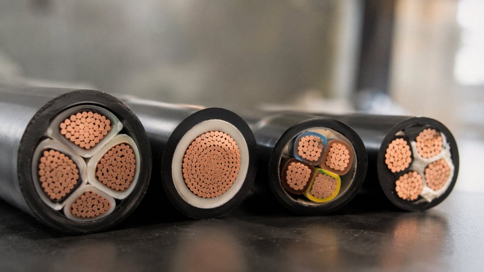
Lead Times by Cable Type — and What They Mean for Scheduling
Standard LV power cable (up to 1 kV, common cross-sections, XLPE or PVC insulation) can typically ship ex-works from a Chinese factory in 4–6 weeks assuming conductor material is in stock. Medium-voltage screened cable — 6 kV to 35 kV, with semi-conductive layers and metallic screen — runs 8–12 weeks because the extrusion process is more complex and factory test scheduling adds time.
Specialty types get longer. Mining cable and fire-resistant cable with mineral insulation or mica-tape construction typically need 10–16 weeks. Custom HV cable orders with witnessed factory acceptance tests (FAT) — partial discharge, voltage withstand, sheath integrity — should be budgeted at 16–24 weeks minimum, and that assumes no drawing approval back-and-forth.
The practical implication: a procurement manager who requisitions MV cable eight weeks before the site needs it has already failed the schedule. Buffer at least one standard deviation above the nominal lead time, especially for first-time orders with any manufacturer.
Drum Lengths, Packaging, and ISPM 15 Compliance
Standard export drum lengths for LV cable are typically 500 m or 1,000 m; MV cable usually ships on 500 m drums due to weight constraints on wooden flanges. Steel drums cost more but are preferred for longer lengths of heavier MV or HV cable and for sea freight in humid climates.
Wooden drums exported to the EU, USA, Australia, and several other markets must comply with ISPM 15 — the international phytosanitary standard that requires heat treatment or methyl bromide treatment of raw wood packaging to prevent pest transfer. Non-compliant drums get quarantined at the destination port. The delay can run weeks and the demurrage cost adds up fast. Always confirm ISPM 15 certification marks on drum documentation before the container is sealed.
Wooden cable drums for export to the EU, USA, and Australia must carry ISPM 15 phytosanitary treatment marks to clear customs without delay.True
ISPM 15 (International Standards for Phytosanitary Measures No. 15) is enforced by customs authorities in the EU, USA, Australia, and over 180 other countries. Non-compliant wood packaging materials are subject to re-export, destruction, or treatment at the importer's expense.
Pre-Shipment Inspection: What to Actually Check
A third-party inspection (SGS, Bureau Veritas, Intertek — your choice, not the supplier’s) should be standard practice on any order above roughly USD 30,000–50,000. The inspection scope that actually catches problems:
| Check | Standard Reference | What Failure Means |
|---|---|---|
| Conductor diameter and insulation thickness | IEC 60811 | Undersized insulation → voltage breakdown in service |
| Conductor DC resistance | IEC 60228 | High resistance → excess heat, energy loss, possible fire |
| Spark test on insulated cores | IEC 60502 / factory protocol | Pinhole defects in insulation detected pre-installation |
| Drum metre markings | Manufacturer spec | Short drums discovered only after installation begins |
| Drum label: voltage rating, date, batch | IEC / customer spec | Wrong rating installed; warranty and traceability lost |
Spark test voltage depends on rated voltage — roughly 6 kV for 0.6/1 kV cable, higher for MV. If a manufacturer is reluctant to permit third-party witness of spark tests, treat that as a red flag.
Supply Chain Integration and What It Does for Consistency
Vertical integration matters more than most buyers appreciate. When a manufacturer sources copper rod from the open market, draws it down in-house, mixes its own insulation compound, and runs armoring on its own lines — rather than outsourcing any of those steps — the batch-to-batch consistency across a multi-drum order is noticeably tighter. Jinda’s five production bases operate with in-house copper rod breakdown, compound mixing, and armoring lines, which reduces the sub-supplier variability that quietly causes dimensional drift across large orders. On a 200-drum project, even small inconsistencies in insulation eccentricity compound into field jointing problems.
Payment Terms and Freight Reality
Most Chinese cable manufacturers work on T/T (30% deposit, 70% against B/L copy) or L/C at sight for first-time buyers. Established relationships often shift to open account or extended T/T terms. L/C offers the buyer protection but adds 1–2 weeks of bank processing and costs both parties in fees — worth it for large first orders, generally not worth the friction once trust is established.
On Incoterms: CNF or CIF suits most buyers who have local import handling arranged; DDP makes sense when the buyer has no presence in the origin country and wants a single landed cost. Freight for a standard 20-foot FCL of cable runs roughly USD 1,500–3,500 depending on destination port and current market rates — that range has been volatile since 2020 and should be treated as an estimate, not a budget line item. Insurance on high-copper-content shipments should reflect replacement cost of the copper, not just invoice value, given how fast scrap copper moves.
Frequently Asked Questions About Cable Types
What is the difference between armoured and unarmoured cable, and when do I need armour?
Armoured cable — most commonly Steel Wire Armour (SWA) or Steel Tape Armour (STA) — adds a mechanical protection layer between the inner sheath and the outer sheath. Unarmoured cable has no such layer and relies entirely on the installation method for physical protection.
The practical rule: direct burial in soil almost always requires armour or, alternatively, installation inside a rigid conduit rated for the burial depth and soil conditions. SWA handles longitudinal tensile stress reasonably well, which matters in sloped trenches or where cable weight could cause creep. STA is better suited to protection against radial compression. In practice, a lot of specifiers default to SWA for everything underground, which is usually fine but slightly overkill for short horizontal runs in stable, sandy soil — you pay a 10–20% unit cost premium for armour depending on conductor cross-section and armour wire gauge.
For indoor cable trays, unarmoured is typically the right choice: lighter, easier to terminate, and the tray itself provides the mechanical protection. Running armoured cable through a building’s cable management just to satisfy a blanket spec is a mistake that adds termination labour and complicates gland selection.
SWA cable installed without a proper cable gland providing IP-rated termination loses its mechanical protection rating at every entry point.True
The armour must be bonded and sealed at both ends; an improperly glanded SWA installation leaves the inner cable exposed to moisture ingress and loses the continuity of the protective screen.
Can I use a power cable as a control cable, or vice versa?
No — and this comes up more than it should on retrofit projects where someone is trying to use what’s already on the reel. Power cables are sized for current-carrying capacity; their insulation thickness follows voltage class requirements under IEC 60502 or equivalent. Control cables are built for low-voltage signal circuits, typically 300/500 V or 450/750 V, with thinner insulation, tighter conductor bundles, and colour-coding systems (IEC 60446 and local variants) that automation engineers depend on for consistent identification.
Run 415 V through a cable rated 300/500 V and you’re operating outside the insulation’s design margin. The failure mode isn’t always immediate — it’s gradual dielectric degradation that eventually causes insulation breakdown, often at the worst possible moment. Going the other way and using a beefy power cable for a 4–20 mA signal loop mostly wastes money, creates routing problems, and the core identification colours won’t match your panel drawings.
What does LSZH / LSOH mean and when is it mandatory?
Low Smoke Zero Halogen (LSZH, also written LSOH or LS0H) cables use a halogen-free compound — typically based on ethylene vinyl acetate or similar polymers — instead of standard PVC. When PVC burns, it releases hydrogen chloride gas, which is toxic and corrosive to electronics. LSZH cable produces significantly less smoke and no halogenic acid gases.
Mandatory applications include rail rolling stock and station cabling, road and metro tunnels, hospital critical areas, offshore and marine installations, and data centres in jurisdictions that have adopted EN 50575 (CPR) at Euroclass Cca or above. Some Middle Eastern and Southeast Asian infrastructure projects now specify LSZH as a baseline even where local codes don’t yet require it — procurement managers increasingly see this as a defensible default for any confined or occupied space.
Budget roughly 15–25% more per metre over standard PVC-insulated equivalents. The premium narrows on large-volume orders and widens on small cross-sections where compound cost dominates.
How do I calculate the correct cable size to avoid voltage drop?
The governing reference for most international projects is IEC 60364-5-52, which covers current-carrying capacity and selection. For voltage drop specifically, the working formula is:
ΔV = (ρ × L × I) / A
Where ρ is the conductor resistivity (roughly 0.0175 Ω·mm²/m for annealed copper at 20 °C), L is the one-way cable length in metres, I is the load current in amperes, and A is the conductor cross-sectional area in mm². Acceptable voltage drop limits vary — typically 3–5% for final circuits depending on the standard and application.
Cable sizing is rarely just a voltage drop calculation. You also check current-carrying capacity under the installation’s derating conditions (grouping, ambient temperature, burial depth), short-circuit rating, and earth fault loop impedance. Jinda’s technical team offers free sizing support for project orders, which is worth using on runs above roughly 100 m or in grouped installations where derating stacks up quickly.
What is the difference between single-mode and multimode fibre optic cable?
Core diameter is the starting point: multimode fibre runs 50 µm or 62.5 µm core; single-mode runs 9 µm. The larger multimode core accepts light from LEDs or low-cost VCSELs, making transceivers cheaper, but modal dispersion limits bandwidth-distance to roughly 10 Gbps over 300–550 m depending on the OM grade. Single-mode uses a laser source and has essentially no modal dispersion — it’s the standard for anything beyond 500 m or above 10 Gbps, which covers nearly all campus backbone and all inter-building links.
Single-mode cable itself is often slightly cheaper per metre than high-grade OM4/OM5 multimode. The transceiver cost is where single-mode runs higher, though that gap is narrowing on SFP+ and QSFP28 modules. For any new industrial network infrastructure, single-mode is usually the forward-compatible choice unless the entire run stays under 100 m.
How long do cables typically last, and what affects service life?
IEC standards for medium-voltage cables (IEC 60502-2) are designed around a 30-year service life under normal operating conditions. In practice, the actual life depends heavily on installation quality, operating temperature relative to the rated maximum, and exposure to UV, moisture, and mechanical stress.
Thermal cycling is the main aging mechanism in most industrial environments — repeated expansion and contraction fatigues conductor connections and stresses insulation at termination points. UV degradation is relevant for any cable with outdoor exposure that wasn’t specified with UV-stabilised sheathing. Moisture ingress into improperly sealed joints can reduce effective insulation life dramatically, sometimes to under five years in high-humidity climates.
The compound formulation and extrusion consistency during manufacturing set the ceiling on service life regardless of installation quality. Cross-linked polyethylene (XLPE) insulation consistently outperforms PVC on thermal aging, which is why it’s the default for MV power cables. Manufacturing process control — specifically extrusion temperature consistency and the absence of voids in the insulation wall — matters as much as the raw compound specification.
What certifications should I require from a Chinese cable manufacturer for export orders?
At minimum: IEC type test reports from an accredited third-party laboratory (not just factory self-declaration), ISO 9001 quality management certification, and a factory audit report — either your own or from a recognised inspection body.
For EU projects, CPR (Construction Products Regulation) compliance under EN 50575 with valid Declaration of Performance is required for cables permanently installed in construction works. For the United States and Canada, UL listing or CSA certification is the baseline for most electrical installations. Middle Eastern projects frequently require SASO (Saudi Arabia) or ESMA (UAE) compliance alongside IEC.
Verifying certificate authenticity matters. Cross-check IEC test reports against the issuing laboratory’s public certificate database. Check ISO 9001 certificates against the registrar’s online registry — certificate fraud exists in the market and a photocopy from a manufacturer is not verification. For large orders, factory audits by SGS, Bureau Veritas, or equivalent before shipment add a layer of assurance that documents alone cannot provide.
Selecting the Right Cable Partner for Long-Term Global Supply: Why Manufacturing Depth Matters
By the time you’ve worked through voltage class, conductor material, insulation system, installation environment, applicable standard, and certification requirement, you’re dealing with six interdependent variables — and a wrong answer on any one of them doesn’t usually announce itself at commissioning. It shows up eighteen months later as a ground fault in a cable tray that should have been armored differently, or as a batch of XLPE-insulated cable failing partial discharge tests because the compound wasn’t properly degassed. The decision matrix isn’t academic. It’s the difference between a project that runs quietly for twenty years and one that generates change orders, insurance claims, and a forensic investigation into who specified what.
Working through that matrix systematically — voltage class first, then conductor material, then insulation and sheathing, then environment, then the applicable standard, and finally certification — compresses the error space considerably. Procurement teams that skip steps, or let a low price drive a substitution partway through the chain, are the ones calling manufacturers two years into a project asking why cable from a second supplier doesn’t terminate cleanly with hardware from the first.
Why Vertical Integration Isn’t Just a Marketing Claim
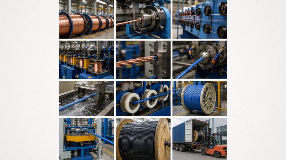
Most cable failures traceable to manufacturing come down to one of three things: conductor purity below the specified grade, insulation wall thickness that’s consistently thin at the low end of tolerance, or armor wires that weren’t drawn from the correct tensile spec. All three are quality problems that originate upstream — at the rod breakdown stage, the compounding line, or the wire drawing mill — and they’re invisible on a finished drum until you cut sections and measure.
A manufacturer that buys pre-drawn conductors and pre-compounded insulation from outside suppliers has limited visibility into those variables. Vertical integration — in-house rod breakdown and conductor drawing, proprietary compounding for PVC, XLPE, and halogen-free formulations, in-house armoring, and a calibrated final test line — doesn’t guarantee perfection, but it does mean that when a tolerance drifts, someone in the same building catches it before it’s wound onto 500 drums destined for a substation project in Saudi Arabia. On a multi-year infrastructure contract where cable is being pulled in phases across eighteen months, batch-to-batch consistency in conductor resistance and insulation capacitance isn’t a nice-to-have. Variation between early and late deliveries can cause protection relay settings to require re-calculation mid-project. That’s a real cost.
Jinda operates five production bases in China covering over 470,000 m² of manufacturing space with in-house conductor drawing, compounding, armoring, and testing capabilities.True
This is consistent with Jinda's published manufacturing profile and represents a verifiable operational footprint that supports the batch consistency claims made in this section.
Jinda’s supply history spans infrastructure cable projects across Southeast Asia, the Middle East, sub-Saharan Africa, and parts of Europe — medium-voltage XLPE distribution cables, armored low-voltage multicore cables for industrial facilities, fire-resistant and halogen-free cables for transit and public building projects, and instrumentation cable for oil and gas installations. Shipment volumes on larger projects typically run in the range of several hundred to a few thousand drum equivalents per order, depending on conductor size and drum configuration. After-sales technical support in those markets isn’t just a phone number — it means providing test certificates traceable to specific production batches, offering re-test sampling on request, and, where projects have local installation engineers unfamiliar with the cable spec, providing termination and jointing guidance documentation in the required language.
The Real Cost of Unverified Low-Cost Cable
Industry loss data on electrical fires and infrastructure failures consistently points to substandard cable as a contributing factor in a meaningful share of incidents — estimates from fire investigation bodies in various markets suggest cable-related failures account for somewhere between 15–25% of electrical fire incidents, though the exact figure varies by country and building stock. The numbers shift depending on the study and the sector, but the pattern holds.
The procurement saving on a substandard cable is usually in the range of 8–18% per meter. The cost of a cable failure in an energized industrial facility — unplanned downtime, switchgear damage, possible injury liability, and the logistical nightmare of re-cabling a buried or tray-installed run — routinely reaches multiples of the original contract value. That arithmetic isn’t subtle, but it gets ignored when procurement cycles are short and budget pressure is high.
Starting a Technical Inquiry
If you’re sourcing cable for a specific project, the fastest way to get a useful technical proposal is to come prepared with five things: the voltage class and relevant installation standard, the required certifications (IEC, BS, UL, or regional equivalent), drum lengths or total meterage by conductor size, the destination port, and any special environmental requirements — whether that’s a high ambient temperature, a corrosive atmosphere, a direct burial installation, or a requirement for halogen-free sheathing. With that information, Jinda’s technical team typically turns around a proposal within roughly 48 hours. Vague inquiries take longer and produce less useful responses, which is true of any serious manufacturer.
On the product development side, Jinda’s current R&D focus includes recyclable halogen-free compound formulations for circular-economy-oriented building projects, aluminum alloy LV cables designed for cost-sensitive grid expansion in emerging markets where copper costs are prohibitive, and subsea hybrid cables combining power conductors with fiber optic elements for offshore wind applications. Those aren’t distant roadmap items — they reflect where grid infrastructure investment is actually heading over the next decade, and they’re the kinds of cable types that procurement teams on long-horizon projects should be asking their suppliers about now rather than later.