Specify the wrong cable type for a conveyor drive panel, and you might not find out until the insulation cracks at -20°C during a winter shutdown, or until heat buildup from an undersized conductor trips a breaker mid-shift. Either failure cascades fast — unplanned downtime, scrap product, a maintenance crew chasing a fault that was baked in at the procurement stage. Choosing the right industrial cable isn’t a detail you sort out after the BOM is approved; it determines whether the installation runs quietly for twenty years or becomes a recurring line item on the maintenance budget.
The four common types of industrial cable are power cables, control cables, instrumentation cables, and data/communication cables. Each serves a distinct function: power cables carry high-current electrical energy to motors and equipment; control cables transmit switching and command signals; instrumentation cables carry low-level sensor signals with tight noise requirements; and data cables handle digital communication between PLCs, drives, and networked devices.
What makes this more complicated in practice is that the same plant floor often needs all four — sometimes bundled in the same cable tray, sometimes in environments that push the limits of standard insulation materials. Understanding where each type fits, what can go wrong when types are substituted or misspecified, and what the procurement variables actually are will save more money and downtime than most other decisions made during a facility build or upgrade.

Power Cables: Construction, Voltage Classes, and Where They Are Indispensable
Power cables do one thing: move electrical energy from where it’s generated or distributed to where it’s consumed. That sounds simple. In practice, the engineering behind that single function spans dozens of construction variables, three distinct voltage classes, and application environments ranging from Arctic tundra to offshore platforms running at 50°C ambient. Getting the specification wrong doesn’t just mean a warranty dispute — it means unplanned downtime, premature insulation failure, or in the worst cases, a fire in a cable tray that takes out an entire production line.
Construction Layers and What Each One Actually Does
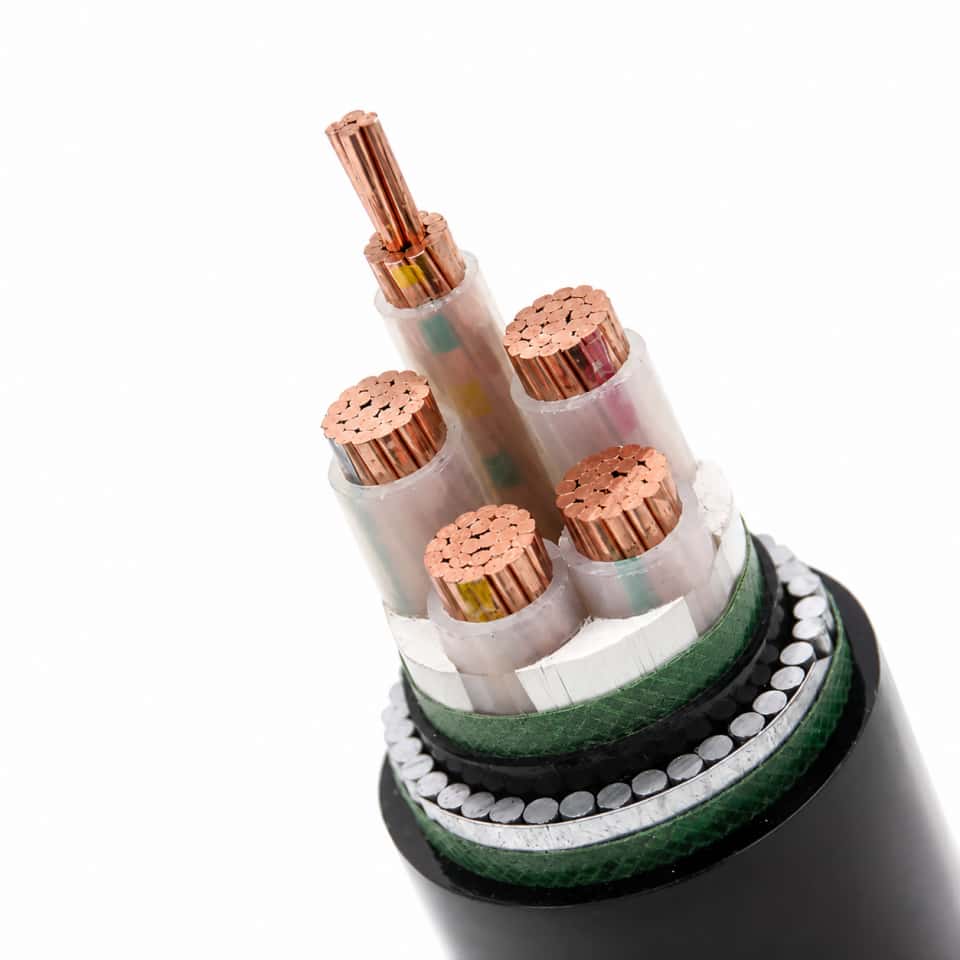
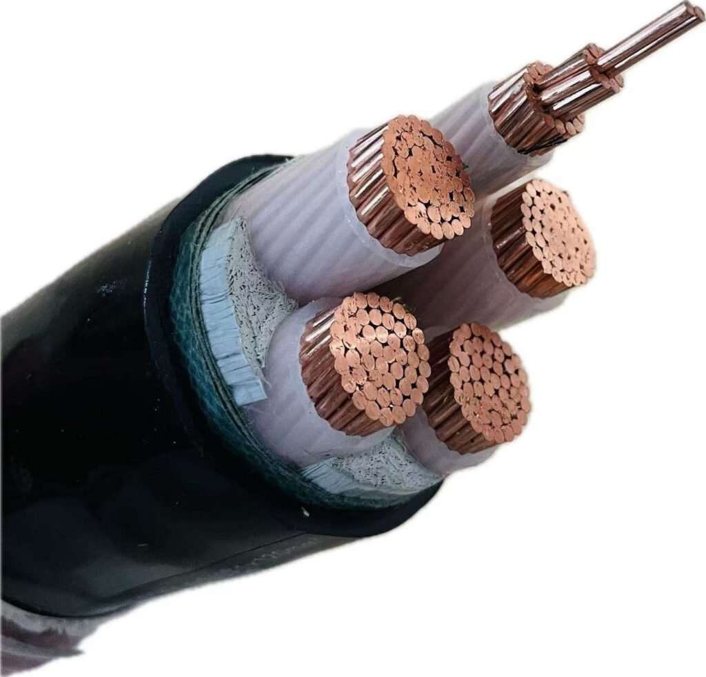
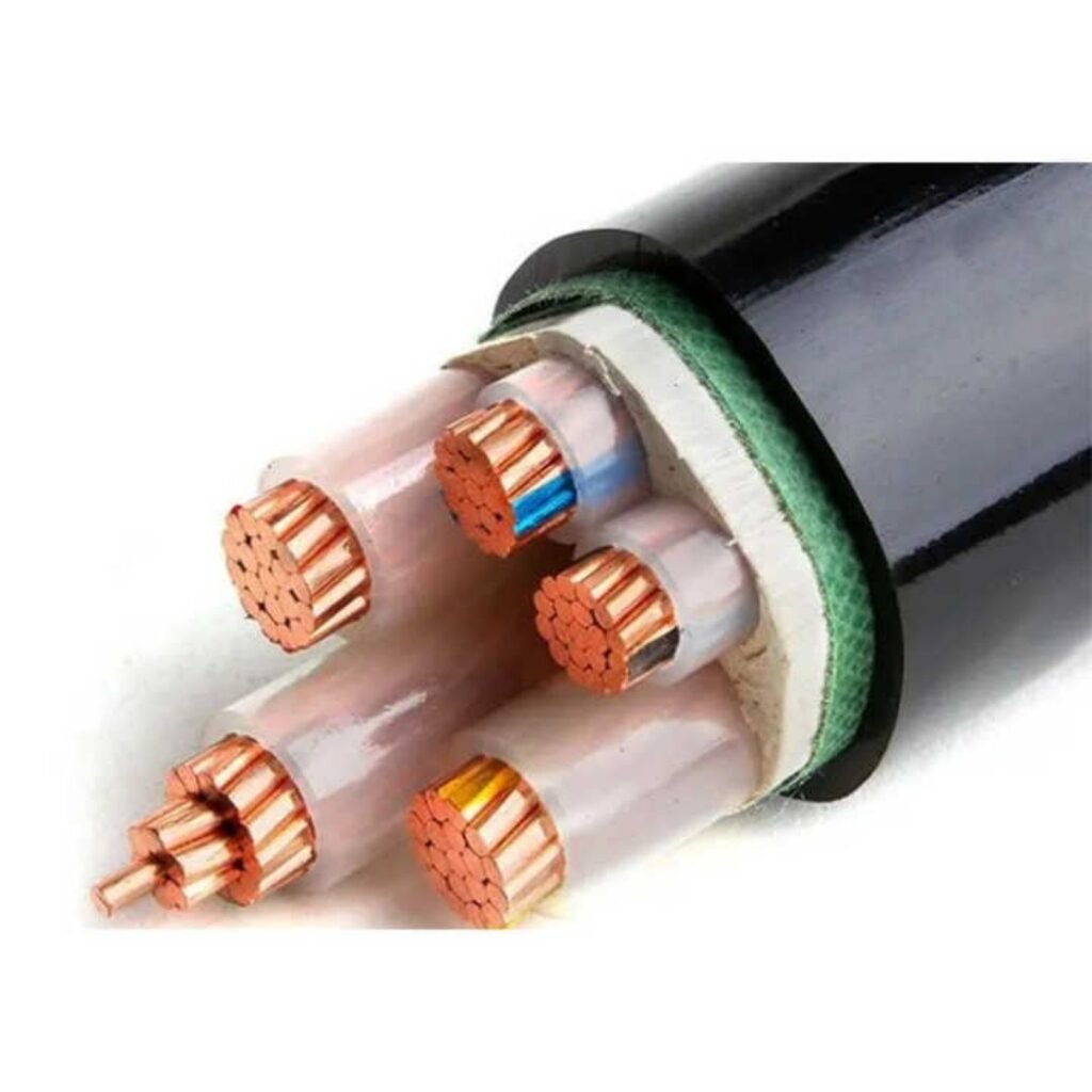
A properly specified power cable is a layered system, not just a wire with a jacket. Starting from the center outward:
The conductor is stranded copper or aluminum. Copper at 99.9–99.99% electrolytic purity is the standard for most industrial power cables; aluminum enters the picture mainly when weight reduction above roughly 30% justifies the larger cross-section and the extra jointing care aluminum demands. Stranding class (Class 2 for fixed installation, Class 5 for flexible runs) affects both flex life and how the cable pulls through conduit.
Insulation sits directly over the conductor. The two dominant materials are XLPE (cross-linked polyethylene) and PVC. XLPE runs continuously at 90°C conductor temperature versus 70°C for PVC — that gap matters more than it sounds, because it directly determines how much current a given cross-section can carry without accelerating insulation aging. XLPE also resists moisture ingress far better, which is why you’ll rarely see PVC-insulated cables specified for direct burial in wet ground on new projects anymore. Service life expectation for XLPE in a well-installed system is 40-plus years; PVC typically delivers 25–30 years, depending heavily on the thermal cycling it sees.
Above the insulation on medium- and high-voltage cables come semiconductive screens — one over the insulation, one under it — which smooth the electric field gradient and prevent partial discharge at the conductor surface. Missing or damaged semi-con layers are a leading root cause of premature MV cable failure that’s often misdiagnosed as “insulation defect.”
Metallic shielding (copper tape, copper wire, or a combination) provides the return path for fault current and screens against electromagnetic interference. Bedding protects the metallic shield from armoring damage during installation. Armoring — steel wire armour (SWA) for most multi-core direct-burial applications, aluminum wire armour (AWA) for single-core cables where a steel armour would create a shorted magnetic loop and unacceptable eddy current losses — gives the cable its mechanical protection rating. The outer sheath, usually PVC or LSZH depending on the installation environment, is the last line of defense against UV, chemicals, and abrasion.
Voltage Classes and the Standards That Govern Them
| Parameter | LV Power Cable | MV Power Cable | HV Power Cable |
|---|---|---|---|
| Voltage range | Up to 1 kV | 1–35 kV | Above 35 kV |
| Typical conductor range | 1.5–400 mm² | 16–630 mm² | 95–2500 mm² |
| Dominant insulation | PVC or XLPE | XLPE | XLPE |
| Primary standard | IEC 60502-1 | IEC 60502-2 | IEC 60840 |
| Core application | Buildings, light industry | Substations, wind farms, mining | Grid transmission, large generation |
Where Power Cables Actually Go
Oil and gas platforms are among the most demanding environments — salt spray, hydrocarbon exposure, mechanical shock from equipment, and the regulatory requirement for flame-retardant or LSZH sheaths in enclosed modules. Wind and solar farms pushed MV cable consumption sharply upward over the past decade; a single onshore wind farm with 50 turbines can require 80–150 km of 33 kV inter-array cable, give or take, depending on turbine spacing and farm layout. Underground urban distribution networks almost exclusively use XLPE MV cables now, largely because the combination of thermal performance and long service life reduces the cost and disruption of re-excavation. Steel mills and mining operations run heavy LV and MV circuits to motor control centers under continuous vibration and occasional fault conditions that would destroy a marginally specified cable within a few years.
XLPE-insulated power cables generally outperform PVC-insulated cables in both continuous operating temperature and moisture resistance for industrial applicationsTrue
XLPE's cross-linked molecular structure raises the maximum continuous conductor temperature to 90°C versus 70°C for PVC, and its lower water absorption rate (typically below 0.01% by weight) significantly reduces insulation degradation in wet or buried installations — both properties are well-documented in IEC 60502 and industry service life studies.
Jinda manufactures power cables through the full LV-to-35 kV range across its dedicated production bases, with IEC 60502 and GB/T compliance built into the production process rather than bolted on at the testing stage. For bulk procurement on infrastructure or industrial projects, the ability to source LV distribution cables and MV inter-array or substation cables from a single qualified supplier with traceable quality documentation usually saves more time in the qualification process than any marginal unit price difference.
Control Cables: Signal Integrity, Multi-Core Configurations, and Automation System Wiring
Control cables are not smaller power cables. That’s the single most common misidentification on the plant floor, and it causes real problems — nuisance trips, corrupted PLC signals, failed interlock sequences. A control cable is a multi-conductor cable purpose-built to carry low-current, low-voltage signals — typically rated to 600 V or 1 kV — that command, regulate, or monitor machinery, switchgear, and automated systems. The currents involved are usually milliamps to a few amps at most. What matters here is signal fidelity, not bulk energy transfer.
Construction: What’s Inside and Why It’s Different
Conductor cross-sections in control cables typically run from 0.5 mm² up to about 6 mm², with 0.75 mm² and 1.5 mm² being the workhorses in most automation panels. Conductors are either solid or finely stranded — stranded is almost universal where there’s any vibration or repeated flexing, which in practice means most factory environments. Each individual core carries its own PVC or LSZH insulation, color-coded or numerically printed. Color coding follows regional conventions (IEC harmonized colors in Europe, or sequentially numbered cores for high-count cables), and the numbering matters more than engineers sometimes admit: pulling a 37-core cable into a panel only to find the printing has worn off the outer cores is a genuine maintenance headache.
The outer sheath is PVC in most general industrial installations. LSZH (low smoke zero halogen) sheaths are specified wherever the cable runs through tunnels, switchrooms, or any space with restricted ventilation and personnel access — the chemistry of combustion products matters as much as flame spread in those environments.
Shielding: The Practical Difference Between a Working System and an Intermittent Fault
This is where control cable specification gets serious. Unshielded control cables run near variable-frequency drives, high-current bus bars, or switching equipment will pick up electromagnetic interference that presents as random signal spikes, false triggers, or drift in analog feedback loops. A properly shielded control cable — overall Al/Mylar foil, overall copper braid, or individually shielded pairs/triads — typically reduces EMI pickup by roughly 40–60 dB compared to an unshielded equivalent. The exact figure depends on shield coverage percentage, drain wire contact quality, and how well the shield is terminated at both ends.
An overall foil-plus-braid shield in a control cable typically achieves 40–60 dB EMI attenuation versus an unshielded cable of the same conductor configuration.True
This range is consistent with IEC and IEEE shielding effectiveness data; actual attenuation depends on shield coverage, termination quality, and frequency range of the interference source.
Individual pair or triad shielding is used where multiple signal types share a single cable run and crosstalk between pairs would corrupt readings — common in process plant where thermocouple and 4–20 mA loops share a conduit path.
Core Count, Spare Cores, and Expansion Planning
Control cables are available from 2-core through to 61-core and beyond. Project engineers typically size core count with a 10–20% spare core buffer above the active requirement — partly for field changes during commissioning, partly because running a new cable through a conduit that’s already full is expensive and disruptive. Functional grouping is worth thinking through early: keeping all cores for a single motor starter in one cable, rather than distributing them across multiple cables, simplifies fault-finding significantly.

Control Cables vs. Instrumentation Cables: A Distinction Worth Getting Right
Control cables carry switched or relay-level signals — start/stop commands, limit switch states, contactor coil drives — at current levels that might reach a few amps. Instrumentation cables handle analog signals at millivolt levels or 4–20 mA loops, where capacitance balance between conductors and ultra-low interference matter more than current capacity. Substituting one for the other in an instrumentation loop usually means baseline noise that corrupts your measurement. They look similar in a cable tray. They are not the same thing.
Where Control Cables Actually Live
The applications are broad: PLC panel wiring in automotive assembly plants, conveyor interlock circuits in distribution centers, motor control center secondary wiring in water treatment facilities, and substation control and protection circuits. In any modern MCC, the control cable count runs into the dozens — every motor, every valve actuator, every safety relay has its own circuit, and the cable management discipline required is substantial.
Relevant standards include IEC 60227 (PVC-insulated cables), IEC 60245 (rubber-insulated variants), and BS EN 50525 for low-voltage wiring cables including LSZH types. Specifying the right standard for the installation environment isn’t bureaucratic box-ticking — it determines whether the cable will perform and whether it will pass inspection.
Instrumentation Cables: Precision Signal Transmission for Measurement and Process Control
Instrumentation cables occupy a genuinely different engineering category from control cables, even though the two are routinely confused on purchase orders. The distinction matters operationally. Control cables carry switching commands — discrete on/off signals at relatively robust voltage levels. Instrumentation cables carry measurement signals: the 4–20 mA loop from a flow transmitter, the millivolt-range EMF from a Type K thermocouple, an RTD resistance reading, or a digital fieldbus packet from a PROFIBUS PA device. These signals are low-energy, low-amplitude, and extremely sensitive to capacitive loading, ground loops, and electromagnetic interference. Treating them as interchangeable with general-purpose control cable is one of the more reliable ways to spend a weekend chasing phantom process upsets.
Electrical Parameters That Actually Define the Category
The engineering specifications that separate instrumentation cable from everything else are specific and testable. Mutual capacitance between conductors in an analog pair should target ≤100 pF/m — higher values progressively roll off high-frequency components of fast-changing signals and introduce phase error in 4–20 mA loops driving HART communication. For RS-485 networks and PROFIBUS DP fieldbus runs, characteristic impedance needs to sit at 120 Ω ±10%; cables wandering outside that range cause reflections and intermittent communication errors that are notoriously difficult to diagnose after installation. DC resistance balance between the two conductors of a pair should stay within roughly 2% — anything looser creates a measurable common-mode voltage that differential receivers partially reject but never eliminate entirely. Insulation resistance is typically specified at ≥1,000 MΩ·km; in humid tropical or offshore environments, cables that barely meet this at commissioning will degrade to marginal values within a few years if the jacket and insulation chemistry aren’t selected carefully.
Shield Architecture: ISP, IST, and Overall Combinations
Construction choice depends on how many independent signal channels run in the same cable and how much inter-channel crosstalk is tolerable. Individually shielded pairs (ISP) give each signal its own Beldfoil or aluminum-polyester tape shield with a drain wire, which is the right choice when channels carry signals from different process loops that must not interfere with each other — say, a temperature input beside a vibration transmitter. Individually shielded triads (IST) add a third conductor for 3-wire RTD circuits without breaking the shield continuity around all three conductors together. Overall-shielded multi-pair cables — one collective shield over all pairs — cost less and route more easily, but they offer no isolation between channels. In practice, most instrumentation engineers specify ISP for analog signal cables and accept overall-shield-only for digital fieldbus trunks where the bus protocol itself handles noise rejection.
Thermocouple Extension and Compensating Cables
This is a sub-category worth treating separately. Thermocouple extension cable uses conductors with thermoelectric properties matched to the specific thermocouple type — Type K, Type J, Type T, and so on — so that the junction formed at the instrument head doesn’t introduce a spurious EMF. Compensating cable uses lower-cost alloys that approximate the thermoelectric curve over a limited temperature range, typically 0–200°C ambient at the cable. Both categories follow IEC 60584-3 color coding, which is not optional if you’re wiring across national borders or rotating maintenance crews. Using mismatched cable — or, worse, substituting copper control cable between the thermocouple and the transmitter — introduces temperature measurement errors that can range from 2–3°C on a good day to 15°C or more at elevated junction temperatures, depending on the thermocouple type and the ambient conditions at the junction. In a fired heater application, that error is not academic.
Using standard copper control cable in place of thermocouple extension cable on a Type K circuit can introduce measurement errors exceeding 10°C depending on ambient temperature at the substitution junction.True
The parasitic thermoelectric EMF generated at the copper-to-Chromel/Alumel junction created by the substitution adds directly to the signal, and the magnitude depends on the temperature differential along the mismatched cable run — this is a well-established principle in thermocouple circuit theory.
Armoring, Hazardous Areas, and Intrinsic Safety
In chemical plant or refinery environments, instrumentation cables frequently run through cable trays shared with heavier power cables, through areas with mechanical traffic, and occasionally direct-buried through soil contaminated with hydrocarbons. Interlocked aluminum armor handles tray environments without excessive weight penalty. Steel wire armor is worth the weight for direct-burial applications or anywhere there’s realistic mechanical abuse risk. The outer jacket chemistry matters here — PE jackets resist hydrocarbon absorption and UV degradation better than standard PVC in most outdoor refinery environments, though PVC remains acceptable for indoor runs.
For Zone 1 and Zone 2 hazardous areas under ATEX/IECEx, intrinsically safe (IS) instrumentation cables carry a blue outer sheath as a mandatory identification requirement. Beyond color, IS cables are specified with limited conductor cross-section (often 1.5 mm² or less) and deliberately low capacitance to ensure the total cable capacitance stays within the limits set by the associated Zener barrier or galvanic isolator. Exceeding those capacitance limits compromises the energy-limiting function of the barrier — the whole point of intrinsic safety as a protection method.
The Reliability Case
In a refinery DCS system with roughly 2,000 field instruments, correct instrumentation cable specification — ISP construction, verified capacitance compliance, proper IS cable in hazardous zones — reduces signal-related fault calls by an estimated 30–40% over a 10-year operating period compared to sites where instrumentation and control cables were interchanged during construction to simplify procurement. The faults that remain tend to be physical damage and connector issues, which are findable. The faults avoided are the intermittent, environment-sensitive signal anomalies that consume disproportionate maintenance hours and occasionally trigger spurious process shutdowns.
Flexible and Specialty Cables: Mechanical Endurance, Environmental Resistance, and Niche Industrial Roles
Most cable selection conversations start and end at voltage class and conductor size. Flexible and specialty cables don’t fit neatly into that framework — and that’s exactly where spec errors get expensive.
Conductor Construction: Why Stranding Class Determines Service Life
The defining characteristic of a flexible cable isn’t the jacket or the shielding. It’s the conductor geometry. Standard power and control cables use Class 1 or Class 2 conductors — solid or mildly stranded — which are adequate for fixed installations but crack under repeated bending. Flexible cables use Class 5 or Class 6 stranding per IEC 60228: dozens to hundreds of fine wires bundled together, which distribute bending stress across the cross-section rather than concentrating it at any one point.
Class 6 cables — the finer of the two — are engineered specifically for cable track (e-chain) and robotic arm applications, where the cable runs through a guided carrier that cycles continuously. In multi-axis robotic cells running three shifts, that translates to somewhere between 500,000 and well over 1 million flex cycles over a cable’s operational life, depending on bend radius, cycle speed, and ambient temperature. Run a Class 2 cable in that environment and you’re looking at conductor fatigue failures inside six months. The repair isn’t just the cable — it’s lost production time and, in some robotic cells, recalibration.
Key Sub-Categories Worth Understanding Separately
Trailing cables for mobile mining equipment — continuous miners, shuttle cars, longwall shearers — face a punishment regime that no standard flexible cable survives: ground contact, repeated coiling and uncoiling, petroleum exposure, and mechanical impact. These cables use heavy armoring (steel wire braid or flat steel tape), oil-resistant neoprene or EPR outer sheaths, and conductor designs that tolerate constant dragging. Voltage ratings typically run from 600 V up to 5 kV depending on the haulage system.
Welding cables are a specialized case: very fine Class 6 stranding, heat-resistant rubber insulation (usually EPDM or natural rubber compound), and bare copper conductors sized to handle high intermittent current — typically 50 mm² to 120 mm² for industrial MIG and submerged arc applications. The flexibility here isn’t about flex cycles; it’s about the welder physically dragging and repositioning the cable all day.
Elevator traveling cables come in flat or round construction, designed to hang in a moving loop between the car and the shaft wall. The flat format keeps the cable from tangling during travel; round traveling cables are used in higher-speed or longer-travel installations. Both require torsion resistance as well as flex endurance.
Robotic flex cables for multi-axis arms add another layer: controlled lay angles on the stranding, sometimes fillers and inner wraps tuned to the exact bend radius of the cable carrier, and often combined power-and-signal construction to reduce the cable bundle diameter through tight robot joints.
Fire-Resistant Cables: Circuit Integrity Under Flame
These are not the same as fire-retardant cables, and conflating the two categories is a genuine safety risk.
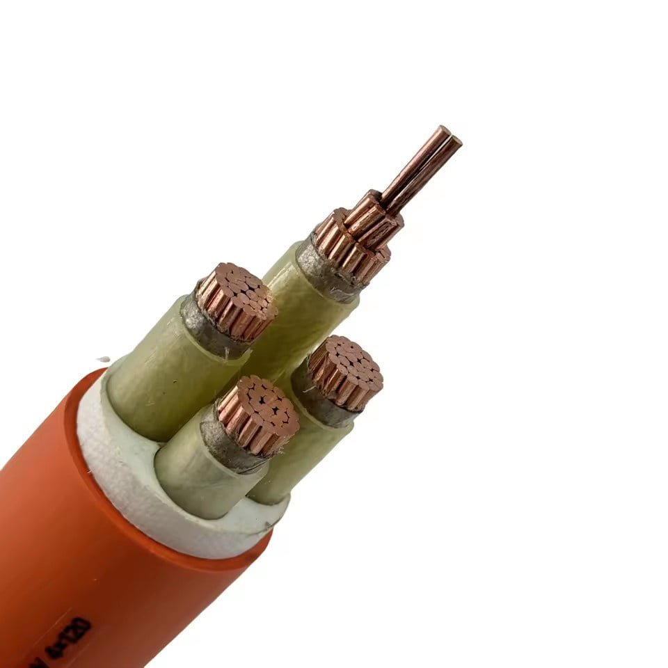
Fire-retardant cables resist flame spread. Fire-resistant cables maintain electrical function during a fire — an entirely different requirement. Mineral insulated copper-clad (MICC) cables, with their compressed magnesium oxide insulation inside a seamless copper tube, survive sustained exposure above 950°C for up to 3 hours. They’re used for fire pump feeders, emergency lighting circuits, and smoke control damper actuators — anywhere the circuit must stay live while a building burns.
For installations where MICC’s rigidity is impractical, fire-resistant XLPE or LSZH-insulated cables per IEC 60331 maintain circuit integrity at 750–850°C with added mechanical shock resistance. These are the more common choice in commercial buildings and transit tunnels.
Standard PVC cable insulation can release up to 28% HCl by weight when burned.True
PVC contains chlorine by composition; combustion converts this to hydrogen chloride gas, which in enclosed spaces forms corrosive hydrochloric acid mist. This is the primary driver for LSZH mandates in confined infrastructure like tunnels, ships, and data centers.
That HCl gas problem is exactly what LSZH (Low Smoke Zero Halogen) compounds address. Beyond the corrosion risk to equipment and infrastructure, standard PVC smoke reduces visibility in evacuation corridors faster than the heat does. LSZH compounds cut smoke opacity by over 80% and eliminate halogen acid gas output, meeting IEC 61034 (smoke density) and IEC 60754 (halogen acid gas) — both required by specification in offshore platforms, rail vehicles, and public buildings across most European and Middle Eastern markets.
Outer Sheath Materials: Matching Chemistry to the Environment
The jacket compound is often the last thing specified and the first thing that fails. PVC is cheap and adequate for dry indoor use. In outdoor, oil-exposed, or chemically aggressive environments, the options branch considerably:
| Sheath Material | Key Strength | Practical Limitation |
|---|---|---|
| PVC | Low cost, flame retardant | Poor cold flexibility below -15°C; releases HCl in fire |
| PUR (Polyurethane) | Cut and abrasion resistance 3–5× PVC; flexible to -40°C | Higher cost; not ideal for strong acids |
| CPE (Chlorinated PE) | Good oil and ozone resistance | Moderate flexibility at low temperatures |
| CSP / Hypalon | Excellent chemical and UV resistance | Cost; less common in standard distribution |
| TPE (Thermoplastic Elastomer) | Recyclable; good flexibility range | Mechanical strength depends heavily on compound grade |
PUR is the default choice for cable track applications in machine tools and automotive assembly plants. In outdoor solar farms, UV-stabilized XLPE becomes the sheath and insulation of choice — TÜV-certified PV cables in 1.5–6 mm² sizes handle DC string voltages up to 1,500 V, with UV and ozone resistance built into the compound rather than applied as an additive layer.
Submersible pump cables add water-blocking tape, longitudinal sealing, and conductor insulation robust enough for continuous immersion — not just splash resistance. Offshore umbilical cables are effectively small bundles of specialty cables plus hydraulic hoses, armor, and strength members in a single cross-section, and they’re engineered project by project.
Jinda’s R&D team handles custom flexible and specialty cable development against client-supplied specifications, with prototype-to-production timelines running roughly 30–45 days for standard flexible designs — longer for anything requiring new tooling or compound qualification. For procurement managers working on projects with non-standard operating environments, that development path is worth opening early rather than after the BOM is locked.
Side-by-Side Comparison: Choosing the Right Cable Type Using a Decision Matrix
The four cable types covered above do not compete with each other — they serve fundamentally different electrical and mechanical roles. Confusion between them, particularly between control and instrumentation cable, or between standard power cable and fire-resistant variants, accounts for a disproportionate share of commissioning delays and in-service failures on industrial projects. The matrix below consolidates the key specification parameters in one place.
Comparison Matrix: Four Cable Types at a Glance
| Parameter | Power Cable | Control Cable | Instrumentation Cable | Flexible / Specialty Cable |
|---|---|---|---|---|
| Primary function | Energy transmission to loads | Command and logic signals | Low-level measurement signals | Dynamic movement, extreme environments |
| Voltage rating (typical) | 0.6/1 kV up to 132 kV+ | 300/500 V to 0.6/1 kV | 150 V to 300/500 V | 300/500 V to 0.6/1 kV (application-dependent) |
| Conductor size range | 1.5 mm² to 1,000 mm²+ | 0.5 mm² to 6 mm² | 0.5 mm² to 2.5 mm² | 0.5 mm² to 150 mm² |
| Conductor class | Solid (Cl.1) or stranded (Cl.2) | Stranded (Cl.2/5) | Fine-stranded (Cl.2/5), often twisted pair | Fine-stranded (Cl.5/6), flex-rated |
| Insulation options | XLPE, PVC, EPR | PVC, LSZH, XLPE | PTFE, PE, PVC, LSZH | PVC, PUR, silicone, TPE |
| Shielding | Rare (except MV screened) | Overall braid or foil optional | Individual pair + overall shield standard | Overall or per-core, application-driven |
| Armoring | SWA, AWA, wire braid | SWA optional | SWA or wire braid optional | Wire braid, steel strip (trailing); often none |
| Key IEC standards | IEC 60502, IEC 60228 | IEC 60227, IEC 60228 | IEC 60502, IEC 61158 (fieldbus) | IEC 60245, IEC 60227, IEC 62893 |
| Operating temp range | -30°C to +90°C (PVC); up to +130°C (XLPE) | -40°C to +80°C | -40°C to +105°C (PTFE variants higher) | -60°C to +90°C (PUR); up to +200°C (silicone) |
| Representative industries | Power generation, O&G, mining | Automotive, water treatment, building automation | Petrochemical, steel, pharmaceuticals | Robotics, crane/hoist, offshore, tunneling |

Five-Step Selection Logic
Step 1 — Identify the signal type. Is the cable carrying load current to a motor or heater (power), discrete on/off commands to solenoids or relays (control), low-level analog or digital process signals (instrumentation), or operating in continuous flexing or chemically aggressive service (flexible/specialty)? This single question eliminates two or three wrong answers immediately.
Step 2 — Determine voltage and current. A 4–20 mA loop running at 24 V DC has no business being specified to 0.6/1 kV insulation — that adds cost — but it absolutely requires proper shielded twisted pairs to protect signal integrity. Conversely, undershooting insulation class on a 6.6 kV feeder is a safety failure, not a cost saving.
Step 3 — Map the environmental hazards. Temperature extremes, UV exposure, hydrocarbon splash, mechanical impact, rodent risk, EMI from variable-frequency drives nearby — each narrows the insulation and jacket material choice. In practice, a single cable run can cross multiple hazard zones, and you spec to the worst one.
Step 4 — Confirm installation method. Fixed buried direct in ground, laid in a cable tray, pulled through conduit, dragged in a festoon system, or coiled in a robot track — these are not interchangeable. A Class 2 stranded conductor in a drag-chain application will work for a while, then fail through conductor fatigue, usually at the worst possible moment.
Step 5 — Check regulatory and certification requirements. ATEX or IECEx if the area is classified hazardous. CPR compliance (Euroclass Eca through Aca) if the installation is in a European building or public infrastructure. UL listing if the end market is North America. IEC 60332 fire-test compliance if code requires it — and increasingly, codes do.
Three Worked Examples
Mine dewatering pump at 6.6 kV. The load is 250 kW submersible, the environment is permanently wet, with mechanical damage risk during installation and occasional tensile load as the cable hangs vertically. Correct specification: medium-voltage XLPE-insulated, copper-screened, 6.6/11 kV rated, armored with round wire for tensile support, with an outer polyethylene sheath rated for permanent water immersion. IEC 60502-2 governs the construction. Using a standard 0.6/1 kV SWA cable here — which does happen — results in insulation breakdown within months.
PLC cabinet controlling 24 motorized valves, water treatment. The signals are 24 V DC discrete I/O, the cabinet is indoors and clean, runs are short (under 50 m), but the environment has intermittent chlorine vapor. The right answer is a multi-core control cable, LSZH jacket, 0.75 mm² conductors, 24–48 cores depending on how many signals share a run, overall foil shield if VFDs are nearby. PTFE insulation is overkill here and roughly 3–4× the cost. Standard PVC would work on chlorine exposure up to a point, but LSZH is the better long-term choice in occupied plant buildings.
120 thermocouple sensors in a steel reheat furnace. Each sensor produces a millivolt-level signal — extremely susceptible to induced noise from the furnace’s high-current bus bars and the SCR power controllers nearby. Individual twisted shielded pairs are non-negotiable. Insulation must handle ambient temperatures of 80–120°C at the cable, with localized peaks higher near the furnace skin; PTFE or high-temperature silicone construction is typical for the first meter, transitioning to screened instrumentation cable with an overall LSZH jacket in the tray. Substituting standard control cable here — even shielded overall — introduces enough noise on the mV signal to corrupt temperature readings and cause the combustion control system to hunt. Scrap rates on slab product increase noticeably when this happens.
The Three Misspecification Patterns That Recur
Standard power cable in a location that codes require fire-resistant cable is probably the most financially painful error, because it’s usually caught during inspection or, worse, during a fire incident investigation. Retrofitting fire-resistant cable in an energized plant section is expensive and disruptive — labor and downtime costs run 4–6× the original cable material cost in most facilities.
Substituting control cable for instrumentation cable on 4–20 mA analog loops is common because the cables look similar and price is lower. The result is signal noise, erratic readings, and hours of troubleshooting that skilled instrument technicians will attribute to everything else first.
Fixed-wiring cable in a drag-chain or festoon system fails predictably. The conductor strands work-harden and fracture, usually creating an intermittent open circuit that is agonizingly difficult to locate. Flexible PUR-jacketed cable with Class 5 or 6 fine-stranded conductors costs more per meter, but the TCO comparison is not close.
A Note on Total Cost of Ownership
Unit price is the wrong metric for industrial cable. A cable priced 15% higher but with twice the service life almost always delivers lower TCO once you account for replacement labor, the cost of unplanned downtime (which in process industries typically runs USD 5,000–50,000 per hour depending on the plant), permit-to-work overhead, and potential process scrap. The procurement instinct to optimize on line-item price is understandable, but on cable it reliably costs more in the long run.
Replacement labor and downtime costs in industrial plants typically exceed initial cable material costs by 3–8× over a cable's service life.True
This range is consistent with maintenance cost analyses across process industries, where permit-to-work systems, shutdowns, and skilled-trade labor rates mean even a short cable replacement event generates costs well above the material value of the cable itself.
Industrial Cable Standards, Certifications, and Compliance Requirements by Global Region
Getting the cable type right is only half the battle. If the product doesn’t carry the correct certification for the destination market, it won’t pass the inspector’s checklist, the insurance underwriter’s review, or — in some jurisdictions — the customs clearance process. Procurement teams sourcing internationally run into this constantly, and the consequences range from expensive re-testing delays to outright rejection on site.
The IEC Framework as a Global Baseline
IEC standards form the practical foundation for most of the world’s industrial cable specifications. IEC 60502 governs extruded solid dielectric power cables from 1 kV up through 30 kV — construction, testing, and marking requirements. IEC 60227 and IEC 60245 cover PVC-insulated and rubber-insulated cables respectively. For fire performance, two standards matter most: IEC 60332 (flame propagation, with Parts 1 through 3 covering single-wire, bunched, and category tests) and IEC 60331 (circuit integrity under fire, critical for emergency systems). Most regional standards — even ones with strong national identities — derive from or explicitly reference these IEC documents. Knowing the IEC baseline means you can usually map across regions with less confusion than the certification alphabet soup suggests.
Europe: CPR, CE, and ATEX
The EU’s Construction Products Regulation (CPR, Regulation 305/2011) reshaped European cable procurement after 2017. Any cable permanently installed in a building must carry a Declaration of Performance and CE marking under EN 50575, with a Euroclass rating from Aca (non-combustible, highest performance) down through B1ca, B2ca, Cca, Dca, Eca, and Fca (minimal performance). For most industrial plant cabling — motor feeders, control loops — Dca or Cca is the typical specification, but check the project fire safety strategy, because some facility insurance policies specify B2ca or better. Getting this wrong means the cable is technically non-compliant as a construction product, regardless of its electrical performance.
Hazardous area installations add ATEX Directive 2014/34/EU requirements. ATEX-rated cables need notified-body involvement and specific Ex marking. In practice, specifiers often also invoke IECEx for projects outside Europe to keep a consistent hazardous-area framework.
North America: UL, CSA, and NEC
North American compliance runs through UL listings (e.g., UL 44 for thermoset-insulated wire, UL 83 for thermoplastic) and CSA certifications for Canadian projects. Conductor ampacity follows NEC Article 310 tables in the United States — these aren’t just guidelines, they’re code. A cable that meets IEC electrical parameters but lacks a UL listing won’t be accepted by most U.S. electrical inspectors. Plan for this early; UL testing takes time and money, and some IEC-standard constructions require reformulation to qualify.
Middle East, Australia/New Zealand, and Emerging Markets
Saudi Arabia’s SASO and the UAE’s ESMA both align closely with IEC, but each requires local conformity marking and registration. In practice, a cable with a valid IEC 60502 test certificate and the manufacturer’s own declaration usually gets through, but project owners and contractors in the Gulf increasingly demand third-party test reports from recognized bodies — KEMA/DEKRA, Bureau Veritas, SGS, or TÜV Rheinland are the names that appear most often in tender documents. Australia and New Zealand follow the AS/NZS 5000 series, which has its own conductor sizing conventions that differ slightly from IEC — a detail that catches importers off guard.
India’s CPRI (Central Power Research Institute) certification is effectively mandatory for power cables entering Indian infrastructure projects. It’s a local testing and approval process, not just a paper exercise.
China’s GB Standards and Dual Certification
China operates under its own GB standards framework — GB/T 12706 for medium-voltage power cables, GB/T 9330 for plastic-insulated control cables. These are not simply translated IEC documents; there are differences in test methods, conductor resistance limits, and marking requirements. Jinda products are dual-certified to both GB and IEC standards, which matters practically: a project team sourcing cables for a domestic Chinese plant and an export installation in Southeast Asia can draw from the same product range without reformulation or parallel qualification runs.
Jinda cable products are certified to both GB and IEC standards, supporting domestic Chinese supply and international export without product reformulation.True
Dual GB/IEC certification is a documented manufacturing and quality-system commitment, enabling compliant supply across Chinese domestic and international project requirements from the same production lines.
Mill Certificates, RoHS, and REACH
Every serious international procurement process should require a full mill certificate — not just a test summary. A complete mill certificate includes conductor chemical composition (for copper, purity should sit in the 99.9% to 99.99% range), mechanical test results on insulation and sheath, and electrical test data including conductor resistance, voltage test, and insulation resistance. If a supplier can’t produce this, that’s a meaningful signal about their quality system.
For cables destined for EU markets, RoHS compliance restricts lead stabilizers in PVC insulation (lead was the standard heat stabilizer for decades; calcium-zinc systems are now the compliant alternative). REACH restrictions on polycyclic aromatic hydrocarbons (PAHs) in rubber compounds add another layer — rubber cable jackets can contain PAHs from process oils, and concentrations above SVHC thresholds create customs and legal exposure. Ask for substance declarations explicitly; don’t assume compliance because the cable meets IEC electrical requirements.
How to Evaluate a Cable Manufacturer: Quality Benchmarks, Factory Audit Criteria, and Supply Chain Reliability Signals
Sourcing industrial cable internationally is not like buying a commodity. A coil of cable that looks identical to spec on paper can fail an installation audit, trip a protection relay, or degrade within two years in service — all because somewhere in the supply chain, a shortcut was taken that no certificate will tell you about. Here is what actually matters when you sit across the table from a supplier, or walk their floor.
Raw Material Traceability
Start at the wire rod. Copper rod mill certificates should trace back to a named smelter and show conductivity values, typically expressed as % IACS, along with oxygen content and temper classification. Polymer batch records for PVC, XLPE, or silicone compounds matter too — particularly for high-temperature or flame-retardant sheaths, where the difference between a certified compound and a reformulated substitute can mean the difference between passing a vertical flame test and failing it spectacularly. Ask specifically whether the manufacturer produces compounds in-house or buys from third-party chemical suppliers. In-house compounding gives the manufacturer control over formulation consistency; outsourced compounds introduce a variable that is genuinely hard to audit remotely.

In-Process Quality Controls
During any factory audit, you want to see conductor resistance testing per IEC 60228 being performed on production samples, not just on submitted type test specimens. Insulation spark testing should be running continuously on the extrusion line at voltages in the 6–8 kV range, depending on insulation wall thickness. For instrumentation cables, capacitance and attenuation measurements on production lots matter because a shift in compound density or wall uniformity will shift capacitance — and that will affect your 4–20 mA signal accuracy in ways that only show up after commissioning.
Watch for gaps between stated test frequency and actual test records. A manufacturer who runs spark tests at “every 500 meters” should have a data log showing it.
Type Test vs. Routine Test Documentation
Routine test reports issued per production lot provide stronger quality assurance than archived type test certificates alone.True
Type tests are performed once on representative samples to prove a design meets a standard; routine tests are performed on every production lot to verify consistency of manufacture. Relying only on a type test certificate gives no information about whether the actual shipment lot matches the tested design.
This distinction trips up a lot of procurement teams. A type test certificate proves the design was compliant when it was tested — possibly years ago, on a sample made under ideal conditions. The question you need answered is: does this lot, going into this container, meet the same parameters? Routine test reports, issued with a lot number and date, are the answer. Demand them as a contractual deliverable, not a courtesy.
Production Capacity and Lead Time Reliability
Facility size is a rough but useful proxy. A manufacturer operating across 470,000 m² of production space — as Jinda does across its five bases — has the physical infrastructure to run parallel production lines, hold meaningful raw material buffer stock, and absorb a rush order without cannibalizing another customer’s schedule. Small workshops can quote competitive prices, but a 12-week lead time that stretches to 20 weeks under any supply pressure is a real project risk. Ask for on-time delivery data from the past 12 months and look at the variance, not just the average.
Logistics Capability
Containerized export experience matters more than it sounds. Cable reels pack awkwardly, and a supplier unfamiliar with international shipment documentation — packing lists with reel weights and dimensions, fumigation certificates for wooden drums, correct HS code classification — creates customs delays that can sit on a critical path. Incoterms flexibility (EXW through CIF or DDP depending on your logistics setup) is worth confirming early. Port proximity to major export hubs, and the supplier’s established freight relationships, usually show up in whether your first shipment arrives clean or with a stack of correction requests.
Reading an ISO 9001 Quality Manual for Real Signals
ISO 9001 certification is a floor, not a ceiling. What you want inside the quality manual is evidence of statistical process control — control charts on conductor resistance, insulation thickness, or OD measurements — rather than just pass/fail inspection records. Non-conformance rate tracking, with trend data across production periods, tells you whether quality problems are being caught and closed or just counted. A corrective action system that shows closed-loop responses to field complaints is a strong signal of a mature quality culture.
What a Reliable Cable Test Report Looks Like
A credible test report includes: measured conductor cross-section (not just nominal), insulation thickness at both minimum and average measurement points, spark test voltage and pass rate for the lot, conductor DC resistance at 20°C, and — for any shielded instrumentation or control cable — transfer impedance or screening attenuation data. If a report lists only nominal values and a blanket “pass,” treat it as incomplete.
The Under-Gauge Problem and Other Common Risks
Under-gauge conductors are a documented, recurring problem in global cable sourcing. Actual cross-sections running 10–15% below nominal are not rare in the spot-market tier of suppliers. The effect is higher DC resistance, lower current-carrying capacity, and thermal stress that shortens cable life — none of which shows up until something overheats or a protection device fails to coordinate correctly. Recycled-content insulation compounds are a related risk: degraded aging properties mean accelerated embrittlement, which typically appears two to four years into service, well past the point where you can hold a supplier accountable without a fight. Thin or absent armor wires are the third recurring issue, particularly on SWA cables where armor mass is easy to reduce without changing the outer appearance.
Dual sourcing of copper rod, with approved mill qualification records for each source, reduces exposure to single-supplier quality excursions. In-house compound preparation for specialty sheaths eliminates a significant variable in formulation consistency.
Supplier Scorecard: A Working Framework
| Criterion | Weight | What to Measure |
|---|---|---|
| Technical compliance | 30% | Test report completeness, standards certifications, sample testing results |
| Quality system maturity | 25% | SPC evidence, NCR trends, corrective action closure rates |
| Delivery performance | 20% | On-time rate over 12 months, lead time variance |
| Pricing competitiveness | 15% | Total landed cost, not ex-works unit price |
| After-sales technical support | 10% | Response time to technical queries, field complaint handling |
Weight these differently depending on your project risk profile — a safety-critical process plant should probably push technical compliance toward 35–40% and trim pricing accordingly. The scorecard is a tool for structured comparison, not a substitute for a physical audit. If the order is large enough, get on a plane.
Frequently Asked Questions About Industrial Cable Types
What is the difference between a control cable and an instrumentation cable?
This is probably the most common mix-up on project BOM reviews, and it causes real problems. Control cables carry switched or relay-level signals — think solenoid outputs, motor starter commands, pushbutton circuits — at currents up to a few amps and voltages typically up to 1 kV. The signal levels are robust enough to tolerate modest electrical noise.
Instrumentation cables are a different discipline. They handle analog measurement signals in the millivolt-to-20 mA range, thermocouple outputs, RTD signals, or digital fieldbus traffic where capacitance balance, low interference, and impedance matching are the governing parameters — not current-carrying capacity. Substituting a control cable into a 4–20 mA loop usually introduces enough noise and capacitance imbalance to corrupt the signal. In practice, that shows up as erratic PLC readings, unstable PID loops, or nuisance alarms that maintenance teams spend days chasing before anyone checks the cable spec.
Can I use a power cable for control wiring if it has enough cores?
Not advisable, and “it fits the conduit” is not a valid engineering justification. Power cables are designed and type-tested for energy transmission. They don’t have the tight capacitance control, conductor balance, or shielding architecture that control and instrumentation circuits depend on. Beyond signal integrity, cross-use creates a compliance headache: your FAT documentation, insurance audit trail, and as-built drawings all start to conflict. Inspectors notice. Stick to purpose-designed cables; the cost difference per meter is small compared to a commissioning delay.
What does LSZH mean, and when is it mandatory?
LSZH — Low Smoke Zero Halogen — describes insulation and sheath compounds that, when burned, emit minimal smoke and no halogen acid gases. Standard PVC cable burns and releases hydrogen chloride, which is both toxic and severely damaging to electronics and switchgear in the vicinity of a fire.
LSZH is mandatory or code-required in enclosed spaces where evacuation is difficult and secondary equipment damage is unacceptable: metro tunnels, airports, offshore platforms, hospitals, and data centers are the typical cases. In Europe, the Construction Products Regulation (CPR) formally classifies cable fire performance and effectively mandates LSZH-class performance in many building and infrastructure applications. If you’re supplying cable to a European or Middle Eastern infrastructure project, check the CPR classification requirement before finalizing the spec — specifying standard PVC and then being forced to reorder is an expensive lesson.
How many flex cycles can an industrial flexible cable withstand?
Depends heavily on the cable class and application geometry. Class 5 flexible cables in moderate-radius applications are typically rated for roughly 50,000–100,000 flex cycles — adequate for occasional movement but not continuous machine travel. Class 6 cables, engineered specifically for cable track (e-chain) applications, are rated for 1 million or more cycles at bend radii as tight as 5× the cable diameter, depending on the manufacturer’s design and verified test protocol. Real-world cycle life also depends on installation quality: a cable routed with insufficient slack in the chain, or twisted during installation, will fail well short of its rated cycles regardless of what the datasheet says.
What is the maximum continuous operating temperature for XLPE-insulated power cable?
Standard XLPE insulation is rated at 90°C continuous conductor temperature, 130°C under emergency overload, and 250°C at short-circuit peak. Some enhanced XLPE compounds push continuous service to 105°C. These figures matter for ampacity calculations — a cable derated because ambient temperature wasn’t properly accounted for is effectively undersized, and running it hot accelerates insulation aging faster than most thermal models suggest in real operating cycles.
Standard XLPE power cable insulation is rated for 90°C continuous conductor temperature with a 250°C short-circuit peak.True
These ratings are established under IEC 60502 and IEC 60364-5-52 and are consistent across major international standards bodies. They reflect the thermal endurance of crosslinked polyethylene and are the basis for published ampacity tables.
How do I confirm that a cable manufacturer’s export documentation is sufficient for my country’s import inspection?
Request the complete quality documentation package before you commit to a purchase order, not after. That means: IEC-compliant type test reports from an accredited third-party laboratory (KEMA, SGS, Bureau Veritas, or equivalent), routine test certificates issued per production reel or drum, material compliance declarations covering RoHS and REACH, and country-of-origin certificates. For some markets — Saudi Arabia, Nigeria, India — additional SASO, NAFDAC, or BIS certifications may be required at the port. Jinda prepares a destination-specific documentation package for each export order, which reduces the risk of a customs hold or rejected shipment on arrival.
What armoring type should I specify for direct-burial power cable in a coastal industrial zone?
For direct burial in corrosive coastal soil, specify double steel tape armour (DSTA) or steel wire armour (SWA) with a corrosion-resistant outer sheath. Polyethylene sheathing is preferred over PVC in aggressive soil or high-moisture environments because of its superior moisture barrier and chemical resistance — PVC can become brittle and lose adhesion to the armour layer over time in acidic or saline ground. One point that gets missed surprisingly often: for single-core medium-voltage cables, use aluminum wire armour rather than steel. Steel armour on a single-core AC cable forms a closed magnetic circuit and generates eddy current losses significant enough to reduce ampacity and cause localized heating. Aluminum wire armour avoids that entirely.
Jinda’s Global Supply Capability and How to Start a Cable Procurement Partnership
Sourcing industrial cable internationally sounds straightforward until you’re three weeks into a project and discover your supplier can’t produce the MV armored cable and the LSZH control cable under the same quality management system — which means two audit trails, two sets of test certificates, and two shipping schedules to reconcile. That’s a procurement headache that compounds fast on a tight commissioning timeline.
Jinda was established in 1987, which in cable manufacturing terms means the company has been through enough raw material cycles, export regulation changes, and quality standard revisions to have built processes that actually hold under pressure. Five production bases across China, covering over 470,000 m² of manufacturing space and staffed by more than 1,000 employees, give the operation enough physical depth to handle volume surges without pulling production from other customer orders. The integrated structure — R&D, production, sales, technical support, and after-sales under one management system — matters more than it sounds. When a site engineer in Poland needs a clarification on partial discharge test results at 11 PM local time, there’s a technical team that can respond, not just an export coordinator.
What the Product Range Actually Covers
The breadth here is worth being specific about. LV power cables covering standard building and industrial wiring, MV cables up to 35 kV for substation feeders and underground distribution, multi-core control cables in configurations from a handful of pairs up to the dense bundles used in DCS panels, individually shielded instrumentation cables for analog 4–20 mA loops and thermocouple extension circuits, flexible trailing cables for mobile equipment, fire-resistant cables meeting IEC 60331 survival requirements, and LSZH variants for confined or ventilated spaces where halogen gas toxicity is a design constraint. All of it built under one quality management system.
That one-system point isn’t marketing language. When a procurement manager consolidates cable supply with a single manufacturer, the test report formats are consistent, the conductor material traceability runs through the same raw material supplier, and there’s no gap in responsibility when a cross-cable-type compatibility question comes up during commissioning.
Consolidating cable procurement with a single qualified manufacturer can reduce procurement overhead — coordination time, documentation reconciliation, audit cost — by roughly 20–35% compared to managing multiple specialist suppliers.True
This range reflects documented vendor-reduction program outcomes reported in procurement literature and engineering procurement construction (EPC) project reviews; actual savings depend on project cable mix complexity, supplier geography, and internal procurement team size.
How the Export Process Works in Practice
Jinda’s export sales team works in English and handles Incoterms from EXW through CIF and DAP, which gives buyers the flexibility to use their own freight forwarder or hand off logistics entirely. Container-load optimization is offered as a service — useful when you’re ordering multiple cable types with different drum sizes and need to fill a 40′ HC without wasting cubic meters or paying for a second container on a short-order balance. Documentation packages are built to IEC standard references and can be structured to meet regional certification requirements across 50-plus countries.
The engagement sequence for new clients is deliberately structured to minimize wasted time on both sides. Submit a project specification — even a draft BOM or a single-line cable schedule is enough to start. Jinda’s technical team reviews it and returns a compliant product proposal, typically within 2–3 business days. Samples are dispatched for approval testing before any commercial commitment. The commercial offer covers pricing, lead time (which honestly varies — 4 to 10 weeks depending on cable type, quantity, and conductor pricing at the time), and payment terms. Production runs with in-process quality hold points, pre-shipment inspection can be arranged with a third-party inspector of the buyer’s choice, and technical support continues after delivery.
In practice, the customers who get the most value from this setup are EPC contractors and project developers who have a full cable schedule and want one technically capable counterpart to own it end to end.
If you have a project specification, a request for quotation, or even just a cable type question that hasn’t been answered yet, Jinda’s international sales team responds within 24–48 hours.