Wrong cable specification on a new production line doesn’t announce itself — it shows up six months later as nuisance tripping on a VFD circuit, or as insulation failure during a summer heat spike that takes down three shifts and costs more in emergency rewiring and lost throughput than the entire original cable budget. Procurement teams under schedule pressure routinely treat cable as a commodity line item, selecting on unit price and delivery lead time alone. That’s the real source of most cable-related downtime: not product defects, but misapplication — wrong voltage class, wrong jacket chemistry for the process environment, wrong flex rating for a moving axis.
Industrial cables are the physical infrastructure that carries power, control signals, and data across every sector of manufacturing, energy, mining, and infrastructure. They serve applications ranging from 300 V instrument loops to 500 kV transmission lines, handle currents from under 1 A in sensor wiring to over 3,000 A in heavy feeder runs, and are engineered — through insulation material, shielding, armor, and jacket selection — to survive the specific electrical, mechanical, thermal, and chemical conditions of each deployment environment.
The global market for these products is pushing toward USD 350 billion by the early 2030s, which sounds abstract until you consider what’s actually driving it: aging grid infrastructure being replaced in Europe and North America, rapid industrial buildout across Southeast Asia and the Middle East, and the electrification of processes that used to run on hydraulics or pneumatics. All of that means more cable decisions, made faster, with higher consequences for getting them wrong. Understanding what industrial cables actually do — functionally, not just categorically — is where sound specification starts.

Power Delivery Applications: How Industrial Cables Feed Machines, Motors, and Entire Production Lines
Walk through any large manufacturing facility — an automotive stamping plant, a cement works, a petrochemical complex — and the cable infrastructure follows a very deliberate hierarchy. It starts at the utility entry point, usually a substation receiving 33 kV to 110 kV from the grid, steps down through medium-voltage distribution, and terminates at individual motor starters and control panels. Most sites run all three voltage tiers simultaneously, often within the same cable trench.
From Substation Entry to Motor Terminal
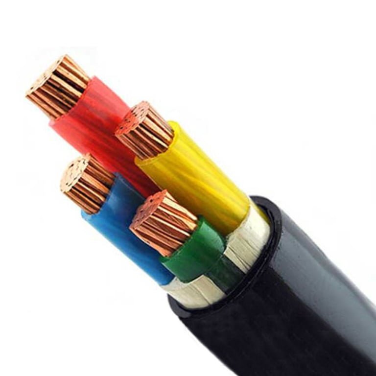
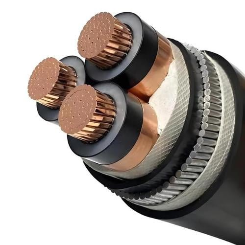
At the top of the stack, high-voltage XLPE cables in the 33 kV–110 kV range carry bulk power from the utility connection into the site’s main substation. XLPE is the standard here — it handles the thermal cycling better than paper-insulated lead-covered (PILC) cable and supports the 30–40 year service life that justifies the capital spend. From the main substation, medium-voltage feeders (typically 6 kV, 10 kV, or 35 kV depending on country standard and plant size) distribute power to zone substations or motor control centers spread across the facility. Finally, low-voltage cables rated 0.6/1 kV connect distribution boards to individual loads — motors, heaters, lighting circuits, compressors.
Each tier carries different engineering concerns. At 10 kV, the dominant issue is insulation integrity over decades; at 0.6/1 kV, it’s current-carrying capacity, voltage drop on long runs, and fault loop impedance. A cable that’s correctly rated for one tier is simply the wrong tool for another.
Why Derating Makes Oversizing the Rule, Not the Exception
Conductor sizing follows ampacity tables from IEC 60364-5-52 or NEC Article 310, but those tables describe ideal single-cable conditions that almost never exist on a real plant floor. Grouping cables in trays reduces heat dissipation — once you have six or more current-carrying conductors bundled together, a correction factor of 0.5 or lower is not unusual. Ambient temperature above the assumed 30°C base also cuts rated current. For underground runs, soil thermal resistivity matters significantly; dry sandy soil can run 2.0–3.0 K·m/W versus 0.7–1.0 K·m/W for moist clay, and that difference alone can derate a cable by 25–35%.
The cumulative effect of stacked derating factors routinely requires a cable one or two cross-section steps above the “calculated” minimum. On a long 10 kV underground feeder, a cable rated 240 mm² on paper might need to be specified at 300 mm² or 400 mm² once grouping, soil resistivity, and an allowance for future load growth are all applied. This is normal engineering practice, not conservative padding.
Combining grouping, temperature, and soil derating factors can reduce a cable's effective current-carrying capacity by 20–50% versus its nameplate rating in controlled single-cable conditions.True
IEC 60364-5-52 correction factor tables confirm that stacked derating from grouping (factor as low as 0.38 for heavily bundled trays), elevated ambient temperature, and poor soil thermal resistivity can cumulatively reduce ampacity by this range in realistic industrial installations.
Copper vs. Aluminum: The Procurement Trade-Off Nobody Should Ignore
Copper’s conductivity is roughly 58 MS/m versus aluminum’s 35 MS/m — meaning a copper conductor carries the same current in about 60% of the cross-sectional area. For final connections to motors, control panels, and any termination that will be broken and remade during maintenance, copper is nearly always preferred. Aluminum oxide forms rapidly on cut surfaces and increases contact resistance if terminations aren’t properly prepared with anti-oxidant compound and the right lugs.
For large-section feeder cables above roughly 185 mm², the economics shift. Aluminum conductors typically run 30–40% cheaper on material cost, and the weight reduction matters on long overhead runs or cable trays already near their load limit. A 630 mm² aluminum feeder on a 500-meter run between substations can save meaningful money — provided the contractor understands aluminum termination practice, which not all do. Specifying aluminum and handing it to a crew trained only on copper is a common source of hot joints and premature failure.
Armoring Options Matched to Installation Environment
The mechanical protection layer is not a one-size decision. Steel wire armor (SWA) handles direct burial and situations where significant tensile loading or rodent exposure is a concern — it’s the default for underground HV and MV cables in most markets. Steel tape armor (STA) provides crush resistance rather than tensile strength, making it a better fit for cables pulled through conduit or laid in cable trays where bending and compression are the threats. Aluminum wire armor (AWA) is used specifically on single-core cables where steel would create eddy-current losses from the alternating magnetic field of a single-phase conductor; AWA avoids that problem while still providing useful mechanical protection.
Subsea and wet-trench installations typically layer SWA over a bedding compound, sometimes with a polypropylene yarn serving — the armoring spec for a harbor crossing reads very differently from a standard land-based direct burial route, and substituting one for the other usually ends badly within a few years.
Fire Performance: No Longer Optional in Most Jurisdictions
IEC 60332-1 and 60332-3 cover flame propagation — a cable can pass these tests and still produce dense smoke and toxic halogen gases that incapacitate personnel and damage electronics. That’s not an acceptable outcome in a tunnel, an offshore platform, or a crowded cable basement. Flame-retardant (FR) cable limits how far a fire spreads along the cable run but doesn’t survive the fire itself. Fire-resistant (FRC) cable, tested under IEC 60331, must maintain circuit integrity at 750–850°C for 90–180 minutes depending on the grade — critical for emergency lighting, fire pumps, and evacuation systems. Low-smoke zero-halogen (LSZH) insulation and sheathing compounds eliminate the hydrogen chloride and hydrogen fluoride that PVC releases when burning; the survival-time criterion is secondary to the toxicity and corrosivity benefit in occupied spaces.
Increasingly, infrastructure projects — metro systems, offshore platforms, data centers, public buildings — specify LSZH plus IEC 60331 fire resistance plus IEC 60754-1 halogen content testing as a combined package. That combination adds roughly 15–30% to cable cost depending on conductor size and order volume, but in a tunnel fire scenario the consequence logic is straightforward: a cable that fails after ten minutes of flame exposure will almost certainly cause the kind of incident that shuts the project down permanently.
Motor and Drive Control Cables: Connecting Variable-Frequency Drives, Servo Systems, and Actuators
Walk into almost any modern production facility and you’ll find variable-frequency drives running pumps, compressors, conveyor motors, CNC spindles — the list is long. VFDs are genuinely useful. They save energy, enable precise speed control, and reduce mechanical shock on startup. But they also generate high-frequency common-mode currents that most buyers never think about until something goes wrong.
Why VFDs Are Harder on Cables Than a Simple DOL Starter
When a VFD switches its IGBT transistors — typically at frequencies between 2 kHz and 16 kHz, depending on the drive model and application — it produces steep voltage rise times, often in the range of 0.1–1 microsecond. Those fast transitions don’t just drive current through the motor winding; they couple capacitively onto the motor cable’s conductors and, through the motor frame, back into the shaft bearings. The result is bearing fluting: a washboard pattern of electrical erosion pits that can destroy an otherwise healthy bearing in 12–18 months of continuous service. Simultaneously, the high-frequency noise circulates through ground conductors back to the control panel, and if the motor cable isn’t properly shielded, that noise lands in signal wiring, PLC analog inputs, and encoder feedback lines. Spurious faults, erratic positioning, phantom alarms — all of it traces back to one decision made during procurement: using standard flexible power cable instead of a purpose-built VFD cable.
It’s a surprisingly common substitution. The cables look similar. The cost difference stings at the purchasing stage. The failure shows up six months later, usually on night shift.
What a Compliant VFD or Servo Cable Actually Looks Like
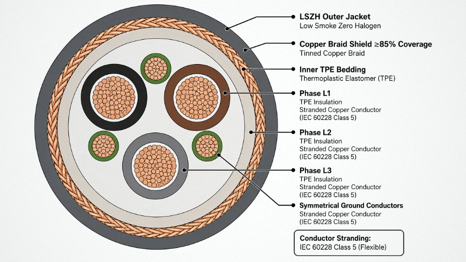
The construction requirements aren’t arbitrary. A properly specified VFD cable uses fine-wire stranded copper conductors — IEC 60228 Class 5 or Class 6 — because coarser conductors develop fatigue cracks at the strands over time, especially in anything that moves. The insulation is typically TPE or TPU rather than standard PVC; both resist the oils, coolants, and hydraulic fluids that drip onto cables routed across machine bases, and they handle repeated flexing without the surface cracking that opens a path for moisture ingress.
Shield coverage matters enormously. Below roughly 85% optical braid coverage, attenuation above 10 MHz becomes unreliable, and that’s precisely the frequency range where VFD common-mode currents cause the most damage. The best constructions use a symmetrical arrangement — three symmetrically placed copper ground conductors under the braid, sometimes combined with an LSZH or foil sub-screen — which keeps the cable’s inductance geometry balanced and reduces ground loop impedance. Shielding effectiveness for a well-built servo cable should reach 60–90 dB across the relevant frequency range; a standard flexible power cable may offer essentially none.
Trailing Cables and Continuous-Flex Environments
Robotic arm umbilicals, crane festoon systems, and linear transfer lines add another constraint: the cable bends continuously, thousands of times per day, for years. Dynamic bend radius in these applications can be as tight as 4× the cable’s outer diameter. At that radius, a cable built around a rigid filler or coarse-strand conductors will see conductor fatigue failure long before the machinery needs any other maintenance. Flex-cycle life requirements for these applications typically start at 5 million cycles and can reach 20 million or more for high-cycle robotics — the cable construction, lay length, and jacket compound all have to be engineered together, not assembled from commodity components.
Standard Flexible Cable vs. Purpose-Built Servo Cable
| Parameter | Standard Flexible Power Cable | Purpose-Built VFD / Servo Cable |
|---|---|---|
| Conductor stranding | IEC 60228 Class 5 (coarser strand) | IEC 60228 Class 5 / Class 6 (fine wire) |
| Insulation wall | Standard, per voltage class | Thin-wall, optimized for capacitance |
| Shielding | None or minimal drain wire | ≥85% copper braid, symmetrical ground conductors |
| Shielding effectiveness | <20 dB (if any) | 60–90 dB across 1–100 MHz |
| Flex-cycle life (4× OD dynamic) | 100,000–500,000 cycles (typical) | 5–20 million cycles depending on construction |
| Jacket material | PVC | TPE or TPU, oil- and abrasion-resistant |
| Typical cost premium | Baseline | 30–80% higher, depending on cross-section and shield spec |
That cost premium is real, and procurement managers will push back on it. The honest counter-argument: one unplanned VFD shutdown to chase down EMI faults, replace a fluted motor bearing, and debug PLC alarm logic will typically cost more in labor and lost production than the cable upgrade for an entire machine.
IEC 60228 Class 6 conductors provide meaningfully better flex-cycle life than Class 5 in continuous-flex servo applicationsTrue
Class 6 specifies finer individual wire strands at a given cross-section compared to Class 5, which reduces the stress amplitude per strand during bending and extends fatigue life — this is well-established in both IEC documentation and independent flex-cycle testing from cable manufacturers and academic fatigue studies.
Jinda’s VFD and servo cables are manufactured and tested to IEC 60228 Class 5 and Class 6 conductor standards, with third-party test reports provided as standard practice for international customers — not as an optional add-on. For buyers specifying these cables into export projects or third-party-audited facilities, that documentation matters more than the datasheet alone.
Instrumentation and Signal Cables: Preserving Accuracy in Sensors, PLCs, and SCADA Systems
Signal integrity is where most procurement decisions quietly go wrong. A buyer saves a few cents per meter on instrumentation cable, substitutes a general-purpose screened cable without checking capacitance specs, and six months later the plant is chasing ghost alarms on a temperature loop or getting erratic PID behavior that the controls engineer spends weeks blaming on the transmitter. The cable was the problem the whole time.
What These Cables Actually Have to Carry
The range of signals is wider than most people outside instrumentation realize. A 4–20 mA process loop running back from a pressure transmitter to a PLC analog input card is low-frequency DC, relatively forgiving, but still sensitive to loop resistance and shunt capacitance at longer runs. A 0–10 V analog output from a positioner sits at higher impedance and picks up interference more readily. Thermocouple extension cables — Types K, J, T, R, and S per IEC 60584 — are a different animal entirely: the conductors must be made from alloys that match the thermocouple’s Seebeck coefficient, otherwise you introduce a parasitic junction and your temperature reading drifts by anywhere from a few degrees to tens of degrees depending on the ambient gradient along the cable run. Substituting standard copper wire for a Type K extension is a classic site mistake, and it causes exactly the kind of slow, plausible-looking error that takes months to catch.
RTD circuits — Pt100 and Pt1000 mostly — demand low, stable lead resistance, which is why three- and four-wire configurations exist. The cable’s conductor resistance and its temperature coefficient matter here. Then you have digital fieldbus: PROFIBUS DP specifies a characteristic impedance of 150 Ω ±20%, FOUNDATION Fieldbus H1 runs at 31.25 kbit/s with a shunt capacitance budget that limits trunk length, and HART sits on top of a 4–20 mA loop as a superimposed 1,200/2,200 Hz FSK signal. Each protocol has its own cable spec. You cannot buy one “instrumentation cable” and call it done.
Capacitance, Twisted Pairs, and Why Run Length Has a Limit
Capacitance per unit length is the number most buyers ignore on the datasheet. For analog loops, a target below 100 pF/m is the usual benchmark — some demanding applications push for 80 pF/m or less. The physics is straightforward: capacitance loads the signal source, attenuates high-frequency components, and at long enough runs it filters the signal enough to cause lag, reduced span, or complete signal collapse. At 100 pF/m and a 1 km run you’re sitting at 100 nF of shunt capacitance across the loop. Whether that matters depends on the transmitter’s output impedance, but it’s not a number to ignore.
Twisting the conductor pair is the other half of the story. Electromagnetic induction from nearby power cables induces a voltage in any conductor loop. A twisted pair works because the orientation of the loop flips with every half-twist — the induced voltage in one half-twist is equal and opposite to the next, so they cancel. Tighter twist rates reduce the effective residual loop area and improve cancellation. For runs near VFD output cables or bus ducts, tighter is better; the difference between 25 mm and 50 mm lay length can be meaningful in a noisy panel room.
Cable Architecture: Screens, Drains, and the Ground-Loop Problem
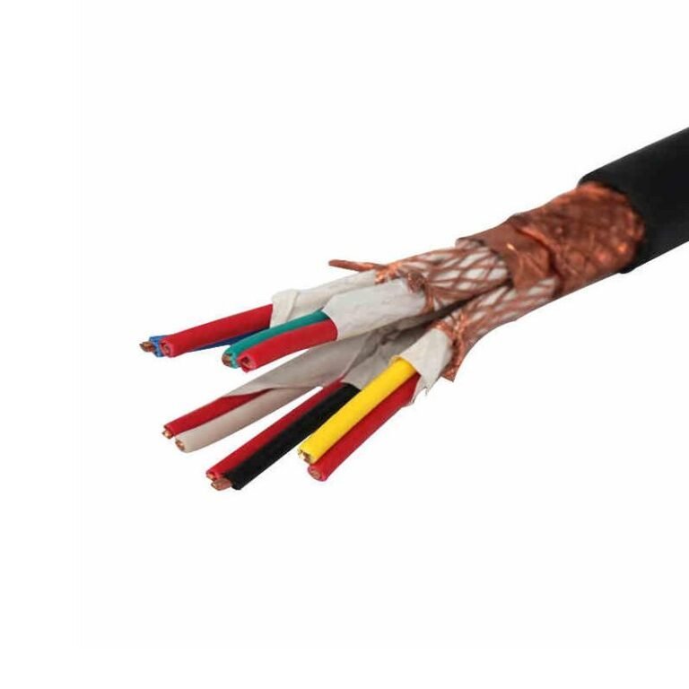
Most multi-pair instrumentation cables use individual pair screens — either foil (aluminum-polyester laminate, lighter, lower coverage) or braid (copper, heavier, higher coverage, better at higher frequencies) — plus an overall collective screen around all pairs. The individual screens stop cross-talk between pairs. The overall screen rejects external field interference. Each individual screen typically has a drain wire — a bare or tinned copper conductor running against the screen foil — to allow a reliable, low-resistance ground connection without puncturing the foil.
Where you ground the screen matters as much as whether you ground it. Ground both ends and you create a conductive loop between two earthing points that are rarely at exactly the same potential. Any difference — even a few millivolts — drives a circulating current through the drain wire, and that current induces a voltage directly in series with your millivolt-level signal. The standard practice is to ground the shield at the control room end only and leave the field end floating. In practice, getting site electricians to respect this rule consistently is harder than it sounds, especially during cable termination on a construction project where dozens of cables land in a day.
Hazardous Areas: Intrinsically Safe Cabling
In Zone 0, Zone 1, and Division 1 classified areas — refineries, pharmaceutical solvent rooms, grain-handling elevators — the cable itself becomes a safety component, not just a conductor. Intrinsically safe (IS) circuits under IEC 60079-14 are designed so that even under fault conditions, the energy available in the circuit cannot ignite the surrounding atmosphere. IS cables in Europe and many export markets are identified by blue sheathing as a visual indicator that the circuit must be segregated from non-IS wiring.
The entity parameters stamped on the barrier or isolator — Voc (open-circuit voltage), Isc (short-circuit current), Ca (maximum allowable cable capacitance), La (maximum allowable cable inductance) — must be checked against the cable’s actual capacitance and inductance per unit length at the installed run length. This is not a formality. Exceed Ca and you’ve invalidated the IS certification for that loop, which is both a safety failure and a compliance issue. Installers sometimes assume any screened blue cable qualifies; it doesn’t unless the capacitance and inductance specs are within the entity parameters for the full run length.
Grounding an instrumentation cable shield at both ends prevents interference better than single-end grounding.False
Grounding both ends creates a current-carrying loop between points at different earth potential, injecting a common-mode offset into the signal. Single-end grounding (typically at the control room) eliminates this ground loop while still providing shield continuity.
Practical Reference: Maximum Recommended Runs by Signal Type
The table below reflects common field practice — not absolute limits, since your actual threshold depends on transmitter output impedance, receiver input impedance, and the noise environment.
| Signal Type | Conductor Size | Key Limiting Parameter | Typical Max Recommended Run |
|---|---|---|---|
| 4–20 mA loop | 0.5 mm² | Loop resistance (max ~1,000 Ω total) | 600–1,200 m depending on transmitter supply voltage |
| 0–10 V analog | 0.5 mm² | Cable capacitance and source impedance | 100–300 m in moderate EMI environments |
| Type K thermocouple | 0.5–1.0 mm² (matched alloy) | Lead resistance and cold-junction error | 200–500 m; longer runs need compensation or field-mounted transmitter |
| Pt100 RTD (3-wire) | 1.0 mm² | Lead resistance balance between legs | Up to ~400 m with matched conductors; 4-wire preferred beyond 200 m |
| PROFIBUS DP (12 Mbit/s) | 0.64 mm² (Type A) | Characteristic impedance, segment capacitance | Max 100 m per segment at 12 Mbit/s; up to 1,200 m at 93.75 kbit/s |
| FOUNDATION Fieldbus H1 | 0.8 mm² | Trunk capacitance budget | 1,900 m total trunk; depends on spur count and power conditioner |
These numbers assume properly screened cable with individual pair foil screens and an overall braid. Run unshielded cable through a cable tray shared with 480 V motor feeds and the effective limit drops dramatically — sometimes to a fraction of these figures.
Industrial Data and Communication Cables: Ethernet, Fieldbus, and Fiber Optic Networks on the Plant Floor
The line between office IT and factory OT has been collapsing for about a decade, and the cable infrastructure reflects that. Except the plant floor is not an office. Temperature swings, hydraulic oil mist, drag-chain flex cycles, and a 400 V motor feeder running 150 mm away from your PROFINET trunk will destroy a standard patch cable in months — sometimes weeks.
Why Office-Grade Cable Fails in Industrial Environments
A typical Cat 6A horizontal cable is rated for static installation in a conditioned building. The jacket is thin PVC chosen for low cost and easy termination, not for resistance to cutting oils, coolant splashes, or UV exposure from skylights and outdoor cable trays. Industrial Ethernet cable — still Cat 6A or Cat 7 in most cases — uses a PUR (polyurethane) jacket that resists oils, remains flexible down to roughly -40 °C, and survives the repeated bending radius demands of a cable drag chain on a CNC machining center or a collaborative robot arm. Some machine tool builders specify IEC 61156-compliant drag-chain-rated cable with a guaranteed flex life of 5–10 million cycles; standard structured cabling offers no such rating at all.
The practical consequence: a procurement manager substituting standard Cat 6A patch cable to save USD 0.30 per meter will typically see intermittent PROFINET timeouts within the first production season, followed by a maintenance diagnostic hunt that costs far more than the cable savings ever would have.
PROFINET, EtherNet/IP, and What the Standards Actually Demand
Both PROFINET and EtherNet/IP run over 100-ohm characteristic impedance cable, which is standard for Cat 5e and above — but the return loss and insertion loss budgets in IEC 61784-5-3 are tighter than you might expect for a 100-meter segment. The 100 m segment length limit is hard; it is not a soft guideline. Route a standard patch cable near a bank of variable-frequency drives without proper separation or shielding, and the high-frequency noise from the drive switching (typically 4–16 kHz carrier, with harmonics well into the MHz range) couples into the data pairs and chews through the return loss budget. The network does not crash dramatically — it just drops packets intermittently, and the SCADA historian starts showing gaps.
Industrial PROFINET cable with an overall foil shield and drain wire reduces this coupling substantially. The shield needs a proper termination at the cabinet end — floating it or connecting it at both ends without understanding the ground reference will make things worse, not better.
Fiber Optic Cable: The Right Answer in High-Interference Plants
In arc-furnace steel mills or induction heating lines, copper data cable becomes genuinely problematic regardless of shielding quality. Fiber is immune to electromagnetic interference by nature. Multimode OM3 supports 10 Gbps runs to roughly 300 m; OM4 stretches that to around 400 m. For campus-scale or cross-building links — say, connecting a remote compressor house to the central control room 2–3 km away — singlemode OS2 handles up to 10 km without a repeater.
Fiber optic cable eliminates both EMI susceptibility and ground-loop issues in industrial environments.True
Fiber carries data as light pulses through a glass or plastic core; it has no electrical conductivity in the signal path, so electromagnetic fields cannot induce noise, and there is no conductive path for ground-loop currents to flow.
A single 12-core armored fiber trunk from a central MDF can realistically replace 40–60 individual copper instrument runs in a greenfield plant. The conduit fill reduction alone is significant. Installation labor drops, and long-term — fiber does not corrode, does not suffer insulation degradation from moisture ingress, and the attenuation characteristics stay stable over a 20–30 year plant life in ways that aging copper pairs simply do not.
Hybrid Cables: One Penetration, Multiple Functions
The category gaining serious traction in wind turbine nacelles, offshore platform topsides, and robotic welding cells is hybrid cable — typically two or four power cores alongside two to twelve fiber or copper data cores, all under a single armored jacket. The engineering logic is straightforward: every penetration through a fire-rated bulkhead on an offshore platform is expensive to seal, certify, and maintain. Combining power and communications in one cable halves or quarters the penetration count. In a wind turbine nacelle, the cable routing from hub to tower base runs through a confined, humid, vibration-prone environment where minimizing total cable count matters both for weight and for serviceability.
The tradeoff is that hybrid designs require careful attention to inter-core crosstalk and shielding isolation — the power cores need individual or collective shielding to keep switching noise from coupling into the data cores. Specifying a hybrid cable correctly means knowing the power core voltage and current, the data protocol’s noise immunity spec, and the minimum bend radius the installation geometry demands. Get those three things right and hybrid cable is genuinely elegant. Get them wrong and you have an expensive, hard-to-diagnose problem sealed inside a bulkhead.
Sector-by-Sector Breakdown: How Oil and Gas, Mining, Renewable Energy, and Heavy Industry Use Cables Differently
No single cable family works across all industrial verticals. The voltage levels, mechanical stresses, chemical exposures, and regulatory frameworks diverge sharply enough that specifying the wrong product family — even one that looks physically similar — routinely causes premature failures, unplanned shutdowns, or failed certification audits. Here is what actually matters in each sector.
Oil and Gas: Upstream Harshness to Subsea Complexity
Wellhead environments are genuinely brutal. Cables at surface installations must resist hydrocarbon contamination, H₂S concentrations that can exceed 1,000 ppm in sour-gas fields, and mechanical abuse from drilling equipment. Mud-resistant outer sheaths — typically a cross-linked polyethylene compound rather than standard PVC — are not optional in these locations; standard PVC softens and cracks under prolonged hydrocarbon contact. Temperature ratings need to cover not just ambient heat but the cyclic heating from wellhead control systems that may sit dormant then run hard.
Offshore platforms and FPSOs introduce a different set of requirements. Fire performance takes priority. IEC 60092-350 governs marine electrical installations, and cables serving accommodation modules, machinery spaces, and escape routes typically need to meet fire resistance under IEC 60331 while also qualifying as low-smoke zero-halogen under IEC 60754. On an FPSO with limited deck space and enclosed processing modules, toxic smoke from burning PVC cables has historically been a major contributor to crew casualty risk in platform fires. LSZH compounds eliminate that particular failure mode.
Subsea umbilical cables are arguably the most complex cable assemblies in any industry. A single umbilical connecting a floating production unit to a subsea Christmas tree at 2,000–3,000 m water depth might integrate hydraulic hoses running at pressures up to 350 bar, multiple pairs of electrical conductors for power and control, and fiber optic elements for data and video — all within a single helically wound, steel-armored assembly roughly 100–150 mm in overall diameter. The design life expectation is usually 20–25 years with no realistic option for mid-life replacement. Getting the lay geometry and armor tension balance wrong causes fatigue cracking at the terminations within a few years.
Mining and Tunneling: Flex Life and Explosive-Atmosphere Compliance
Underground coal and hard-rock mines demand trailing cables that survive continuous flexing on cable reels behind continuous miners and longwall shearers. These cables operate at 6.6 kV or 11 kV, cycle tens of thousands of times over their service life, and work in environments where methane and coal dust create genuine explosion risk. ATEX Category 1 and Category 2 certification governs cable use in Zone 0/1 and Zone 2 classified areas; anti-static outer sheaths — surface resistivity typically controlled below 10⁹ Ω per IEC requirements — prevent static charge accumulation that could trigger dust ignition.
Shaft and elevator applications fall under IEC 62219, which specifies traveling cable construction for vertical motion with controlled flex radius and robust trailing element design.

Renewable Energy: UV Life and Torsion Resistance
Photovoltaic installations look straightforward until you account for 25-year outdoor exposure. DC string and array cables rated to 1.8 kV per IEC 62930 (the current PV cable standard, effectively superseding the earlier TÜV 2 Pfg 1169 in most new project specs) require UV-stabilized and ozone-resistant cross-linked insulation. Thin-wall PVC simply won’t hold up; it chalks and cracks within 5–8 years in high-UV climates, exposing conductors in live DC circuits where arc faults are notoriously difficult to extinguish.
Wind turbines add a mechanical challenge that solar installations don’t face: torsion. The pitch and yaw control cables inside a turbine tower rotate continuously — full 360-degree cycles, thousands of times per year over a 20-year service life. Standard cable constructions fatigue and break strands at bends. Torsion-resistant designs use fine-stranded conductors with optimized helical lay and a jacket compound that doesn’t crack under repeated twist. Medium-voltage export cables running from turbine towers to offshore substations face a separate problem: dynamic submarine cable behavior in strong tidal currents, requiring carefully engineered armor and buoyancy to avoid resonant vibration.
IEC 62930 is the current governing standard for photovoltaic DC cables and effectively replaces TÜV 2 Pfg 1169 for most new project specifications.True
IEC 62930:2017 was developed specifically to standardize PV cable requirements internationally; TÜV 2 Pfg 1169 remains recognized but IEC 62930 is now the reference standard in most utility-scale procurement specifications globally.
Steel, Cement, and Chemical Processing: Heat and Chemical Aggression
Cement kilns and steel reheat furnaces are among the most cable-hostile environments on any plant floor. Continuous ambient temperatures of 180°C–250°C in the immediate kiln zone rule out every conventional thermoplastic insulation. Silicone rubber compounds handle continuous service up to roughly 180–200°C and survive occasional excursions higher; mica-glass insulation extends usable range into the 250°C+ zone and also provides fire circuit integrity. The cost premium over standard XLPE is real — silicone-insulated cable typically runs 3–5× the price per meter — but it’s the only option that doesn’t require annual replacement in those locations.
Chemical plants running acid-wash lines, chlor-alkali processes, or aggressive solvent handling need outer sheaths that won’t be attacked by splash and vapor exposure. PTFE and PVDF sheathing compounds resist a broad range of acids, bases, and organic solvents that would degrade standard PVC or polyethylene over months of exposure. Heat-tracing cables — self-regulating types for freeze protection on water and light-hydrocarbon lines, constant-wattage types for viscous-fluid temperature maintenance — represent a distinct cable subcategory with their own installation and design rules, and under-specifying the watt-per-meter output for a given pipe size and insulation thickness is a surprisingly common procurement error.
Railway and Transit Infrastructure: Fire Certification and Traction Demands
Railway applications split across two very different cable environments. Rolling stock cables — those inside train cars and locomotive bodies — must meet EN 50264 for material and construction requirements, and fire performance requirements under EN 45545-2 are non-negotiable in new rolling stock procurement across the EU and in most export markets that reference European standards. The hazard level classification (HL1 through HL3 under EN 45545-2) determines exactly which fire test parameters apply; specifying HL2 when HL3 is required for an underground transit application is the kind of mistake that gets caught at type-approval stage and delays project handover by months.
Traction power cables for 25 kV AC overhead electrification systems are a separate family entirely — high-voltage, large-section, typically with XLPE insulation and robust mechanical protection for trackside installation. Platform screen door cables and tunnel emergency lighting circuits need both the fire performance and the flexibility for installation in confined track-tunnel geometries. Jinda’s cross-sector cable production experience across these verticals — from offshore LSZH marine cables through to mining trailing cables and PV DC wire — reflects the reality that large infrastructure projects often require multiple specialized cable families from a single supplier capable of coordinating delivery schedules and documentation packages.
Reading and Comparing Industrial Cable Specifications: Standards, Test Methods, and What to Watch Before You Buy
Procurement managers are often handed a vendor datasheet and asked to approve it in 48 hours. That datasheet can look perfectly professional and still conceal a specification gap that causes a motor drive to fail nine months into production. Knowing which numbers matter — and how to verify them — is what separates a competent cable buy from an expensive mistake.
Which Standard Governs Your Project
The applicable standard is determined first by destination market, then by application. IEC 60502 covers extruded-insulation power cables from 1 kV to 30 kV and is the backbone reference for most international projects. IEC 60227 and IEC 60245 apply to PVC and rubber-insulated cables at lower voltages — the workhorse wiring you see everywhere from control panels to portable equipment. Marine installations fall under IEC 60092, which adds flame propagation and halogen content requirements that standard land-based cables don’t face. Explosive atmosphere zones invoke IEC 60079; the cable construction requirements there are substantially stricter, and a buyer who substitutes a standard armored cable in a Zone 1 area has created a compliance and safety problem simultaneously.
For North American destination projects, UL 508C and NEC Article 310 take precedence regardless of what IEC certificates accompany the product. Canadian projects require CSA C22.2. These aren’t interchangeable. A cable certified only to IEC 60502 won’t satisfy a UL listing requirement for a US end-user, and suppliers sometimes present IEC certificates to North American buyers hoping the difference goes unnoticed. Ask the supplier explicitly: “Does this cable carry a UL or CSA listing, or only IEC certification?” The answer changes what you can legally install.
Critical Datasheet Parameters — Don’t Skip These
The rated voltage designation Uo/U/Um is the first thing to verify. Uo is the conductor-to-earth voltage, U is conductor-to-conductor, and Um is the maximum system voltage the insulation must withstand. Misreading this — say, treating a 0.6/1 kV cable as suitable for a 1.1 kV system — is more common than it should be.
Maximum conductor temperature under continuous load is equally important, particularly if the cable runs in a conduit bundle or high-ambient tray. A PVC-insulated cable rated at 70 °C behaves very differently from an XLPE cable rated at 90 °C in the same tray fill calculation.
Short-circuit current rating is often absent from datasheets and needs to be requested separately. For feeders close to a transformer, this matters.
For instrumentation and drive cables, check capacitance and inductance per unit length — values that most power cable datasheets omit entirely. For signal cables, insulation resistance should be at a minimum 1,000 MΩ·km at 20 °C for new product. Below that, you have grounds for rejection before installation even begins.
Physical parameters also bite people: minimum bending radius (static versus dynamic — they differ, and dynamic radius governs cable tray corners and robotic applications), minimum installation temperature (PVC stiffens and cracks below roughly -15 °C to -20 °C depending on compound), and weight per unit length for tray loading calculations. A 500-meter drum of 4-core 95 mm² armored cable weighs more than most engineers visualize when they’re signing off on tray capacity.
Factory Acceptance Tests and What to Ask For
A reputable manufacturer should routinely perform and document the following: high-voltage withstand test between conductor and screen at 2Uo AC or 2.5Uo DC held for five minutes per IEC 60502-1, partial discharge extinction voltage measurement, spark testing on extruded cores, insulation resistance measurement per drum, and dimensional checks against drawing tolerances. These aren’t optional extras. If a supplier can’t produce routine test records — not just type test certificates — for each production drum, treat that as a red flag.
Reading Third-Party Test Certificates Correctly
The accreditation body logo matters. Look for CNAS, ILAC-MRA, UKAS, or TÜV recognition. A certificate issued by a lab with no traceable accreditation is essentially self-certification in formal packaging. Beyond the logo, verify that the cable construction described on the certificate — conductor cross-section, insulation material, sheath compound, armor type — exactly matches what’s on your purchase order. It’s not uncommon to receive a certificate for a 16 mm² single-core cable on a purchase order for 25 mm² multicore. Not the same product.
Test date matters too. For ongoing production surveillance, certificates older than roughly three years should be questioned; compound formulations and process conditions can drift. And confirm the tested sample length matches your order’s conductor size — type tests performed on short lab samples occasionally show performance that full production drums don’t replicate.
IEC 60502-1 requires a 5-minute AC high-voltage withstand test at 2Uo between conductor and metallic screen for medium-voltage cables.True
IEC 60502-1 Table 18 specifies the routine electrical test voltages for power cables 1 kV to 30 kV, including the 2Uo AC test duration requirement of 5 minutes.
Supply-Chain Due Diligence for Larger Projects
For any significant project — anything above roughly 50,000 meters or supplying critical infrastructure — request mill certificates tracing the copper or aluminum rod back to the smelter. Conductor purity directly affects resistance and current-carrying capacity, and the cheapest rod on the market isn’t always what ends up in the cable. Similarly, request insulation compound certification from the compound manufacturer; established compounders like Borealis, Dow, or SACO2 issue compound-level certificates that confirm the material properties the cable’s type test assumed.
Specify witnessed factory inspection for large orders if geography allows, and insist on drum-end testing on delivery — a simple megger check and visual inspection at goods-in that confirms the drum survived transit and hasn’t been swapped. It sounds excessive until you’ve received a drum that left the factory correct and arrived with moisture ingress from a punctured end cap.
How to Select the Right Industrial Cable for a New Project: A Practical Engineering Decision Framework
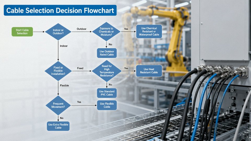
Getting cable selection right at the front end of a project is one of those things that looks straightforward until you’re standing in a congested cable tray at 2 a.m. trying to figure out why a VFD keeps tripping on ground faults. The framework below is sequential on purpose — each step narrows the field before you spend time on the next, which is how experienced engineers actually work through this, rather than jumping straight to a catalogue and picking “something that looks about right.”
Step 1 — Define the Electrical Duty First
Four numbers determine more about the right cable family than anything else: rated voltage, maximum continuous current from your load schedule, prospective fault level and clearance time, and signal or frequency type. A 690 V motor feeder, a 110 V DC control circuit, and a 33 kV substation interconnect are entirely different product families, and confusing them at the specification stage cascades into wrong insulation thickness, wrong dielectric test voltage, and wrong conductor sizing.
Fault level matters more than most buyers acknowledge. A cable serving a bus with 50 kA available fault current needs a conductor cross-section that can survive the thermal energy pulse (I²t) for the clearing time of the upstream protection — often 0.2–0.5 seconds in practice. Undersizing here doesn’t just shorten cable life; it causes catastrophic insulation failure under fault.
Step 2 — Characterize the Installation Environment Systematically
Walk the actual route. Don’t rely on the drawing. A petrochemical plant might show a cable tray routing on paper, but ground-level reality includes direct sunlight for six hours a day, intermittent steam leaks from an adjacent heat exchanger, and forklift traffic crossing the tray every shift.
Map each hazard to a material requirement:
| Environmental Hazard | Insulation / Jacket Requirement | Armor / Screening |
|---|---|---|
| UV exposure, outdoor | XLPE or LSZH-UV jacket | Not required alone |
| Hydrocarbon splash | Neoprene or CSP outer sheath | — |
| Mechanical impact, tray edge | PVC/SWA or stainless braid | Steel wire armor |
| Repeated flexing (drag chain) | Highly flexible stranded conductor, PUR jacket | Braid, not SWA |
| Zone 1 / Zone 2 explosive atmosphere | IEC 60079 certified, LSZH | Tape or braid armor |
| Wet direct burial | XLPE, PE outer, water-blocking tape | SWA or DSTA |
Ambient temperature deserves a real number, not a guess. A cable routed through a furnace area where ambient peaks at 65 °C in summer is not the same specification as one in a temperate warehouse.
Step 3 — Determine Routing and Installation Method
Direct burial drops the cable’s thermal dissipation rating significantly — soil thermal resistivity varies from roughly 0.7 to 2.5 K·m/W depending on moisture content and soil type, and dry summer conditions can push that toward the upper end, derate continuous current by 15–25% compared to open-air values. Cable tray requires checking fill ratio and applying IEC 60364-5-52 grouping correction factors; a tray loaded to 70% capacity with twelve single-core cables carries a very different derating than three cables with air space around them.
For conduit pulls, the practical rule is that the cable’s outer diameter should not exceed roughly 40% of the conduit internal diameter — beyond that, the pull tension required risks damaging the jacket and, depending on cable construction, distorting the conductor geometry. Offshore and marine applications introduce flag-state or class-society approval requirements (DNV, Lloyd’s, Bureau Veritas), and simply sourcing an IEC-compliant cable that isn’t on the approved list will hold up vessel commissioning regardless of technical merit.
Step 4 — Calculate Conductor Cross-Section Properly
Start with load current divided by all applicable derating factors stacked together — temperature correction, grouping factor, installation method factor. That gives minimum conductor area for thermal compliance. Then check voltage drop over the full cable run:
ΔV = I × L × (R·cosφ + X·sinφ) × 2
Target below 3–5% of nominal voltage per IEC 60364-5-52 guidance. For long MV runs — anything over roughly 400–500 m feeding a large motor — voltage drop frequently governs the selection over thermal rating, pushing you up one or even two conductor sizes beyond what the current alone demands.
Step 5 — Apply Lifecycle Cost Thinking, Not Just Purchase Price
A direct-buried cable in a congested industrial estate realistically costs USD 50–150 per meter to replace when you factor in excavation, reinstatement, production downtime, and contractor mobilization — and that range depends heavily on urban vs. rural site, depth, and backfill specification. Comparing that against the procurement price difference between a standard PVC jacket and a premium XLPE/LSZH construction usually justifies the upgrade without any sophisticated analysis.
Worked Example: 1,000 kW Motor Feeder, Coastal Petrochemical Plant
The motor runs at 6.6 kV, power factor roughly 0.87, efficiency around 94%, which gives a full-load current of approximately 100–105 A. The route is 380 m, direct burial in a congested cable corridor, soil thermal resistivity measured at 1.8 K·m/W. Ambient soil temperature at 1 m depth peaks at about 28 °C in this region.
Step 1 confirms: 6.6 kV rated voltage, ~105 A continuous, fault level 25 kA / 0.5 s clearing.
Step 2 flags: coastal chloride-laden atmosphere at the cable pits, buried sections through hydrocarbon-contaminated fill, no explosive zone classification at cable route.
Step 3 identifies: direct burial, grouping factor 0.8 (four similar cables in parallel corridor), depth 1.0 m.
Step 4 calculation: 105 A ÷ 0.8 (grouping) ÷ 0.92 (temperature correction for 28 °C soil) = ~143 A required ampacity. That points to 95 mm² copper in most XLPE MV cable tables at these burial conditions. Voltage drop check: 380 m × 105 A × (0.193 Ω/km × 0.87 + 0.08 Ω/km × 0.49) × 2 / 1,000 ≈ 14 V, which is about 0.21% of 6,600 V — well within tolerance, so thermal rating governs, not drop.
Step 5 check: upgrading to 120 mm² adds roughly 8–12% to cable material cost but adds margin against future load growth and reduces I²R losses by about 20% continuously — given the 6,000–8,000 annual operating hours typical of process plant equipment, that’s recoverable in energy savings within three to five years on a drive this size.
Final specification for the purchase order: 6.6 kV, 95 mm² (or 120 mm² if lifecycle cost approved) copper conductor, XLPE insulation, LSZH inner sheath, double steel tape armor, LSZH/PE outer sheath, IEC 60502-2 compliant, halogen-free per IEC 60754 — sufficient to issue to suppliers without ambiguity.
Applying IEC 60364-5-52 grouping correction factors when cables share a tray can reduce calculated allowable current by 20–40% compared to isolated installation values.True
IEC 60364-5-52 Table B.52.17 and related tables publish grouping reduction factors that reach as low as 0.57 for large groups of cables in contact, representing significant derating that is routinely ignored in preliminary designs and causes premature insulation aging.
The discipline here is doing the steps in order. Skipping environment characterization and going straight to conductor sizing is how you end up with a beautifully calculated 95 mm² cable in a PVC jacket that softens and deforms in its first summer because nobody accounted for the 60 °C ambient above a furnace deck.
Frequently Asked Questions About Industrial Cable Applications, Selection, and Supply
Can I substitute commercial building wire for industrial cable?
Short answer: no, and doing so in most jurisdictions will violate your electrical installation code and void your facility’s insurance coverage the moment an inspector or loss adjuster looks at the job.
The construction differences are significant. Commercial building wire — think standard NM or THHN — is designed for conduit runs in temperature-controlled, low-mechanical-stress environments. Industrial cable carries heavier, tougher jackets (often PVC compound to EN 50525 or thermoplastic elastomer), thicker insulation walls, and in many cases an armoring layer — SWA, AWA, or wire braid — that a standard building cable simply doesn’t have. Shielding, critical for any cable running near variable-frequency drives or high-current switchgear, is absent in commercial wire. The conductor stranding is also usually finer and more flexible in industrial designs to survive repeated flexing, vibration, and installation through conduit bends. An apparent cost saving of 15–30% on cable procurement routinely turns into an insurance claim, a fire investigation, or an extended production shutdown. It’s not worth it.
How long should industrial cable actually last?
Under correct installation conditions — proper de-rating for ambient temperature, no mechanical abuse, sealed terminations — PVC-insulated low-voltage cable typically performs for 20–25 years. XLPE-insulated medium-voltage cable is commonly rated 30–40 years. Armored cables in mining or subsea service tend to reach 15–20 years because mechanical stress cycles accumulate faster than in a static installation.
Premature failures almost always trace back to one of five causes: sustained thermal overload above the conductor’s rated temperature (even 10–15 °C over rated temperature for extended periods accelerates insulation aging noticeably); repeated mechanical damage from abrasion, crushing, or tight bending radius; UV degradation of an unprotected outer jacket — an issue more common in outdoor installations in high-UV climates like the Middle East or tropical Southeast Asia than most buyers expect; moisture ingress at improperly sealed terminations, which causes tracking, partial discharge, and eventually insulation breakdown; and chemical attack where the jacket compound is incompatible with the plant’s process fluids or cleaning agents.
What standards should I specify for export projects in the Middle East, Southeast Asia, or Africa?
IEC is the dominant framework across all three regions. For Gulf Cooperation Council countries, SASO certification (Saudi Standards, Metrology and Quality Organization) is a hard requirement for cables entering Saudi Arabia, and similar national registration schemes apply in the UAE and Qatar — get this confirmed in writing before production begins, not after. In Southeast Asia, Malaysia requires SIRIM certification, Indonesia requires SNI mark, and Singapore’s PSB/SAC scheme covers cables used in regulated installations. These aren’t optional; customs clearance can stall on them.
African infrastructure projects are more varied. Multilateral development bank-funded schemes (World Bank, African Development Bank) generally accept IEC compliance supported by a Certificate of Conformance from an internationally accredited testing laboratory. Jinda holds ISO 9001 certification and can provide full lot-traceable test documentation to satisfy these requirements.
How do I verify that production quality matches the approved sample?
Type-test certificates alone are not sufficient — they prove a cable design passed a test, not that the drums on your dock were made the same way. Specify third-party factory audits, arrange witnessed production runs for large orders, and insist on batch-traceable test reports tied to specific drum serial numbers. Drum-end testing on arrival — conductor resistance, insulation resistance, spark test check — costs very little relative to the risk and catches substituted materials before cables go into the ground.
Jinda's quality management system provides full lot traceability from raw material intake through to finished drum dispatchTrue
ISO 9001-certified manufacturers are required to maintain documented material traceability and in-process inspection records as a condition of certification; this is auditable and verifiable by third-party inspectors
What lead times and minimum order quantities should I plan for?
Standard low-voltage cables are often available from stock or within roughly 2–4 weeks for quantities starting from a single drum. Medium-voltage or specialty cables — think cold-resistant arctic compounds, halogen-free mining grades, or custom conductor configurations — typically run 6–12 weeks for manufacture. Large infrastructure projects above roughly 500 km total cable length should plan for 4–6 months with phased delivery schedules built into the contract; the copper or aluminum raw material procurement cycle alone can drive 6–8 weeks of that lead time depending on market conditions.
Can a damaged cable be repaired in the field?
For low-voltage cables, yes — heat-shrink or cold-applied joint kits with proper conductor cross-connection and re-insulation are a practical field repair, provided the jointer follows the kit manufacturer’s procedure. Medium-voltage cable joints are a different matter. They require factory-trained, pre-qualified jointers using approved kit materials per IEC 60502-4, with controlled environment conditions during application. A poorly executed MV joint will fail — usually at the worst possible time. For any application where reliability is genuinely critical, full section replacement is the right answer regardless of voltage level. Field joints are a workaround, not a restoration.
Why Global Projects Partner with Jinda for Industrial Cable Supply: Capability, Compliance, and Long-Term Reliability
Choosing a cable supplier for a major project is not really about price per meter. It is about whether the manufacturer can hold specification consistency across a 500-drum order, whether the test reports will satisfy a client’s engineer of record, and whether the logistics chain will survive a monsoon season or a Red Sea routing change. Those are the questions worth asking before a purchase order is signed.
Manufacturing Integration That Actually Controls Quality
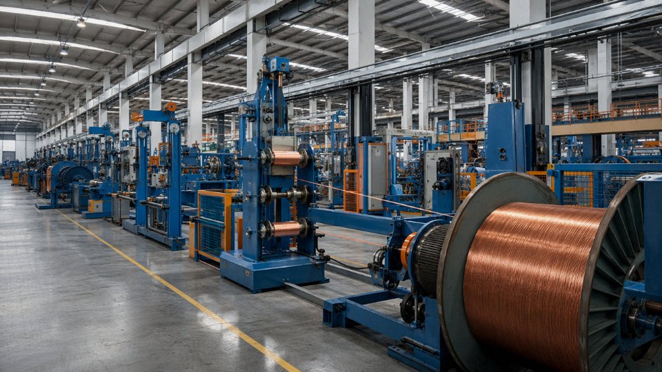
Jinda operates five production bases across China with a combined manufacturing footprint of roughly 470,000 m² — for context, that is large enough to run copper rod drawing, stranding, insulation extrusion, armoring, jacketing, and drum packaging under the same quality management umbrella rather than outsourcing any of those stages to sub-tier suppliers. That matters more than it sounds. In practice, when a manufacturer purchases pre-stranded conductors from a third party and only extrudes the insulation in-house, dimensional tolerances and conductor resistance values can drift batch to batch without anyone catching it until a drum fails a site acceptance test. Vertical integration closes most of those gaps.
The production capacity supports both high-volume commodity runs and lower-volume specialty cable types without the long lead times that smaller integrated manufacturers typically impose when they have to reshuffle production schedules.
Product Range Wide Enough for a Single-Source EPC Strategy
EPC contractors on large petrochemical, power generation, or renewable energy projects often deal with eight or ten cable suppliers per project simply because no single manufacturer covers the full voltage range and cable family list. Jinda’s product portfolio spans low-voltage power cables (0.6/1 kV), medium-voltage cables up through 26/35 kV, high-voltage cables up to 127/220 kV, plus control and instrumentation cables, fire-resistant and LSZH variants, mining cables rated for methane-zone service, photovoltaic DC cables (TÜV-certified 1,500 V DC types), and flexible industrial cables for dynamic applications.
Consolidating a cable bill of materials to one manufacturer does reduce procurement workload, but the real operational benefit is consistency in test report format, certificate traceability, and after-delivery technical support — you are not chasing five different factories when a substitution question comes up during installation.
Standards Compliance Across Multiple Market Regimes
Depending on the project destination, a cable shipment might need IEC 60502 type-test reports for a European-influenced specification, AS/NZS compliance for Australia or New Zealand, UL or CSA listing for North American projects, or GB/T conformance for domestic Chinese installations. Jinda maintains certifications and type-test documentation across IEC, GB, BS, DIN, AS/NZS, UL, and CSA standards, with third-party test reports from SGS, TÜV Rheinland, and CESI available before order placement.
Jinda can provide third-party type-test reports from accredited laboratories including SGS and TÜV Rheinland for project-specification approval prior to order.True
This is stated manufacturer capability consistent with standard practice for ISO 9001-certified cable manufacturers supplying international EPC projects; buyers should request specific report references and confirm scope during pre-qualification.
That last point — having documentation available before the order — is not trivial. Projects regularly stall at the engineering approval stage because a supplier cannot produce compliant test evidence quickly enough. Getting those reports into the client’s approval process early prevents schedule compression later.
Export Experience That Reduces Clearance Risk
Over 35 years of export history to customers across the Middle East, Southeast Asia, Africa, Europe, and the Americas builds a specific kind of operational knowledge that is hard to replicate: familiarity with routing documents for projects in free-trade zones, HS code classification for armored versus unarmored cables in markets where tariff categories are genuinely ambiguous, and the documentation packages — commercial invoices, packing lists, material test reports, certificates of origin — that customs authorities in different regions actually require. A dedicated export documentation team handling that work in-house means fewer clearance delays on time-critical project deliveries.
Technical Partnership, Not Just Transactional Supply
For large projects, Jinda’s application engineering team can review cable schedules, cross-reference competitor part numbers against equivalent Jinda types, and advise on specification optimization — occasionally catching cases where a project schedule specifies a more expensive cable than the installation environment actually demands, or the reverse, where an under-specified type was carried over from an earlier, less demanding project. That kind of pre-order engineering review is common with major cable manufacturers and should be a baseline expectation, not a premium service. It is worth asking any shortlisted supplier whether they offer it.