Specify the wrong cable voltage class on a procurement order — it happens more often than most engineers want to admit — and you can end up with medium voltage product sitting on a loading dock while a building fit-out stalls, or worse, low voltage cable rated below system requirements installed in a feeder run that trips protection relays the first time load swings. Either failure path costs real money: re-procurement lead times of four to twelve weeks on specialty cable, liquidated damages on delayed project handover, and in the worst case, an in-service failure that takes down a distribution board and triggers an insurance investigation.
A low voltage cable is an insulated electrical cable rated for operating voltages up to 1 kV (1,000 V AC) per IEC 60502-1, used to distribute power from switchgear and distribution boards to motors, lighting, sockets, and building loads. Conductor cross-sections typically run from 1.5 mm² for lighting branch circuits up to 630 mm² or larger for main feeders, with copper conductors carrying roughly 1.5–1.7 times the current of an equivalent aluminum cross-section.
What’s less obvious is how much variation sits inside that single voltage class. A 1 kV XLPE armored cable for a solar farm combiner circuit and a flexible PVC-insulated cable pulling through a conduit in a commercial fit-out both qualify as low voltage — same rating on paper, completely different construction, termination method, and procurement path. The global market for this product category ran somewhere between USD 28 and 32 billion in 2023, which tells you just how many distinct applications fall under that one label.

Anatomy of a Low Voltage Cable: Every Layer and the Engineering Reason It Exists
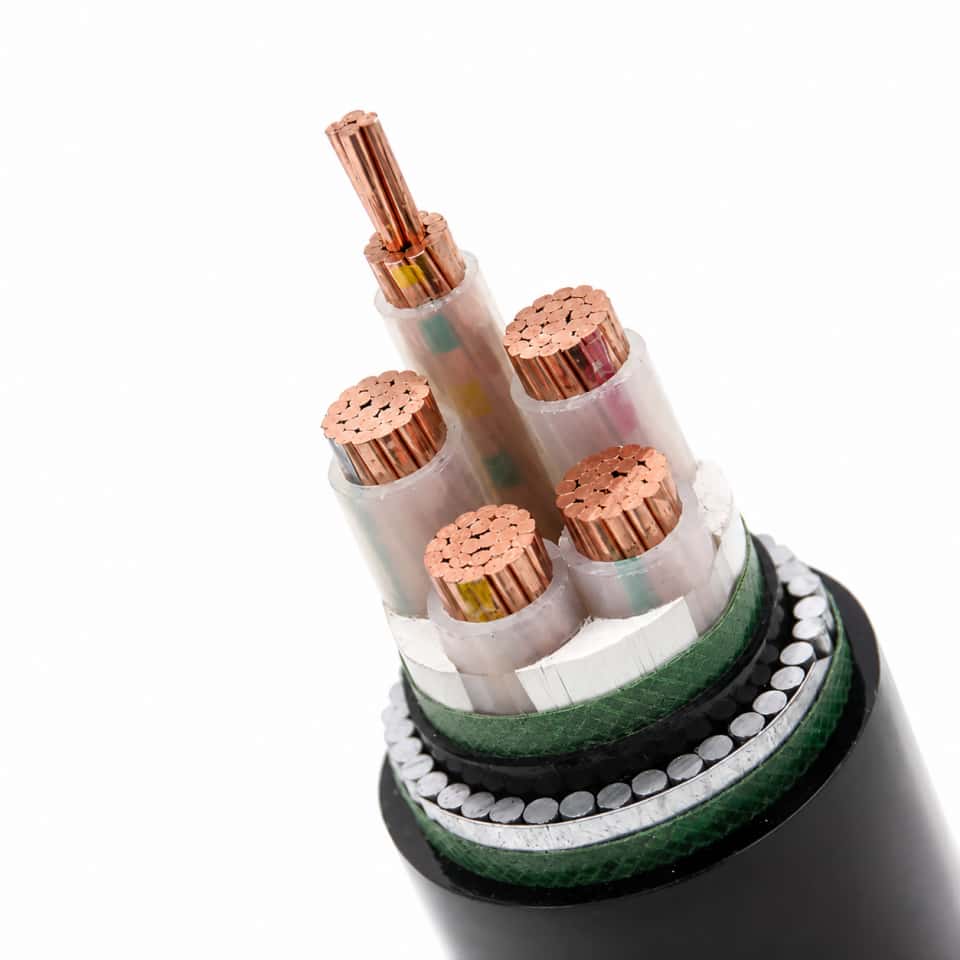
Crack open a cable datasheet and you’ll see a string of abbreviations — XLPE/SWA/LSZH, Class 2 conductor, 90°C rated — that mean everything when you’re specifying for a real installation and nothing if you don’t know what each layer actually does. Here’s the breakdown, layer by layer.
Alt text: Cross-section diagram of a 4-core XLPE-insulated SWA armored low voltage cable showing conductor, insulation, bedding, steel wire armor, and LSZH outer sheath with all layer labels in English
Conductor: The Decision That Drives Everything Downstream
Copper or aluminum, solid or stranded — this choice sets the cable’s weight, termination method, price, and current capacity before you’ve considered a single other variable.
Per IEC 60228, copper conductors come in Class 1 (solid, fixed installations), Class 2 (stranded, standard power cables), and Class 5 (fine-wire stranded, flexible cords and trailing cables). Aluminum is available in Class 1 and Class 2. For most industrial plant distribution and building power circuits, Class 2 copper or Class 2 aluminum is what you’ll actually order.
Copper carries roughly 1.5 to 1.7 times the current of an aluminum conductor at the same cross-section — which means if you switch to aluminum to save money on a main feeder, you’ll need to upsize. How much depends on the installation method and ambient temperature, but the table below gives a practical comparison for two common sizes in free air (approximately 30°C ambient, IEC 60364 reference method E):
| Cross-section | Cu Class 2 — approx. current rating | Al Class 2 — approx. current rating |
|---|---|---|
| 95 mm² | 230–250 A | 175–195 A |
| 240 mm² | 380–420 A | 295–330 A |
Aluminum is lighter (roughly 50% the weight of copper at equivalent length) and cheaper per kilogram, which matters on long overhead or cable-tray runs where structural loading is a real constraint. The catch is termination: aluminum oxidizes quickly, and a poorly prepared lug joint will creep and overheat within months. Bi-metallic lugs and proper anti-oxidant compound are not optional with aluminum — they’re the reason the joint lasts.
Conductor Screen
In most standard low voltage multicore cables you won’t see a conductor screen at all. It’s primarily a medium-voltage feature. That said, some larger multicore LV designs — particularly those running at the upper end of the 1 kV range under high current density — include a thin semiconducting tape or extruded layer over each conductor to smooth electric field concentration at the conductor surface and reduce stress on the insulation wall. If it’s absent from a standard 0.6/1 kV cable, that’s normal and correct, not a cost-cut.
Insulation: Where the Temperature Rating Actually Comes From
XLPE (cross-linked polyethylene) and PVC are the two workhorses. XLPE is rated 90°C continuous conductor temperature, with a short-circuit withstand of 250°C. PVC sits at 70°C continuous, 160°C short-circuit. That 20°C difference in operating temperature translates directly into ampacity — for the same conductor cross-section, XLPE-insulated cables can carry more current continuously than PVC, which is why any circuit running near its thermal limit should be XLPE, full stop.
PVC remains entirely reasonable for light commercial wiring, general building circuits, and cost-sensitive projects where load is modest and well-controlled. It’s cheaper, easier to handle in cold weather without cracking concerns (within reason), and supported by decades of installation practice worldwide.
EPR (ethylene propylene rubber) shows up in flexible cables, mining trailing cables, and subsea or damp-environment applications where you need flexibility at low temperatures and good moisture resistance. It costs more and is less common in standard building distribution, but for a dragline cable or a submarine pump application, it’s often the right call.
XLPE insulation provides a higher continuous operating temperature than PVC, enabling greater current-carrying capacity at the same conductor cross-section.True
IEC 60502-1 and IEC 60364-5-52 both confirm that XLPE-insulated conductors are rated 90°C versus 70°C for PVC, directly increasing permissible current per the standard ampacity tables.
Fillers, Binders, and Bedding
These layers don’t carry current or block voltage, but they’re not padding. Fillers — typically polypropylene string or similar — occupy the gaps between insulated cores in a multicore cable, maintaining a circular cross-section under mechanical load. Without them, cores migrate, the armor bears unevenly, and localized insulation damage follows over years of thermal cycling. Binder tapes hold the assembly together before armoring. The inner bedding layer (often extruded PVC or PE) protects the insulation from direct contact with armor wires and, in some designs, provides an additional moisture barrier. It’s a quiet but functional layer that separates a well-built cable from a cheap one.
Armoring Options
Steel wire armor (SWA) is the standard choice for direct burial, conduit-to-trench transitions, and industrial environments where cable damage from mechanical impact is a genuine risk. Steel tape armor (STA) resists compressive loads — think cables under roadways or in congested cable ducts where radial crush is the threat rather than axial tension. Both work fine for multicore cables.
Single-core cables are a different matter. Steel armor on a single-core AC cable creates a closed magnetic loop around the conductor, inducing eddy currents that generate heat and waste energy — measurably so at higher currents. Aluminum wire armor (AWA) avoids this because aluminum’s lower magnetic permeability breaks the inductive loop. On a single-core 240 mm² cable carrying 350 A, choosing SWA over AWA isn’t just a minor inefficiency; it’s a continuous energy loss and a potential derating problem that will follow you for the life of the installation.
Outer Sheath
PVC sheathing in ST1 or ST2 grades is the default for most general wiring and direct burial applications. It’s tough, UV-resistant enough for most outdoor exposure, and inexpensive. PE (polyethylene) sheathing is preferred for long direct-burial runs and consistently UV-exposed outdoor installations — better moisture resistance and longer UV stability than standard PVC grades.
LSZH (low smoke zero halogen), sometimes written LSOH, is specified whenever cable volume in a confined space creates a toxic smoke hazard: metro tunnels, offshore platforms, data centers, airports, high-rise escape routes. Under IEC 60332-3 flame propagation tests, LSZH cables are required to achieve an oxygen index above roughly 30% (versus around 22–25% for standard PVC) and substantially lower smoke density. In a tunnel fire, the difference between LSZH and PVC sheathing isn’t a datasheet footnote — it’s the visibility available to evacuees and the corrosive damage done to adjacent equipment.
Every layer in a well-specified LV cable exists because a real failure mode justified it. Understanding what each one does means you can read a datasheet critically, push back on substitutions, and catch where a cheaper build is genuinely cutting corners versus where it’s simply appropriate for a lighter application.
Low Voltage Cable Types by Application: Power, Control, Flexible, and Specialty Variants
Picking the wrong cable type for a job rarely fails immediately. It fails six months later — a flexible cable on a festoon system that cracks at the bend point, or a standard power cable installed in an evacuation route that fills a stairwell with toxic smoke. Getting the type right at the specification stage costs nothing. Fixing it after installation is expensive.
Power Distribution Cables
These are the workhorses of any LV system — substation feeders, main distribution board connections, underground mains, industrial plant ring mains. Common designations include NYY and N2XY under DIN VDE 0276, NAYY for the aluminum-conductor variant, BS 6346 SWA in UK and Commonwealth projects, and YJV / YJLV / N2XY equivalents under Chinese GB/T 12706. The insulation is typically PVC (NYY, NAYY) or XLPE (N2XY, YJV), with XLPE preferred for anything that runs warm or needs longer service life — PVC starts losing mechanical integrity above roughly 70°C continuous conductor temperature, while XLPE is rated to 90°C.
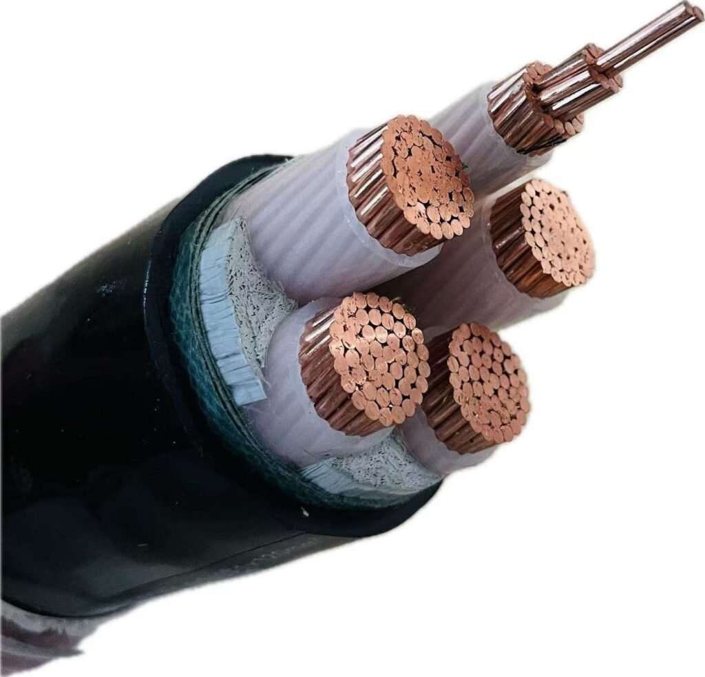
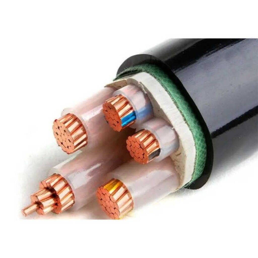
Core configuration is a genuine specification decision, not just a count. Two-core cables go on single-phase circuits where the neutral is managed elsewhere. Three-core handles three-phase balanced loads. Four-core (3+neutral) is the standard choice for most LV distribution where a full-size neutral is needed. The 3+1 and 3+2 configurations — reduced neutral plus separate earth, or reduced neutral with combined earth — are used when the neutral carries only residual unbalance current and you want to save copper or aluminum cost on large conductor sizes. On a 630 mm² four-core aluminum cable run of any real length, that difference in neutral sizing adds up materially on the BOM.

Control and Instrumentation Cables
KVVP, KYJVP, and multi-pair shielded designs live in panels, motor control centers, relay rooms, and the signal wiring between PLCs and field devices. Voltage ratings are usually 450/750 V or 0.6/1 kV — lower than power cables, but the insulation and shielding matter far more than the voltage rating in practice. Individual core shielding on each pair is worth the extra cost in environments with variable-speed drives, large contactors, or any high-frequency switching noise nearby. Overall shielding alone just isn’t enough in a busy MCC room. Twisted pairs reduce EMI pickup through differential cancellation; the tighter the twist, the better the rejection at higher frequencies. Unshielded control cable in an industrial plant is a maintenance headache waiting to happen — spurious PLC faults and unexplained relay trips are the usual symptoms.
Flexible and Trailing Cables
H07RN-F (rubber-insulated, rated 450/750 V) and EPR-insulated mining cables are built for movement. IEC 60245 sets minimum bending radii at 4–6 times the cable diameter depending on the specific type — violate that repeatedly and the conductors fatigue-fracture, usually at the point of maximum repeated bend. Cranes, hoists, festoon systems, and any portable equipment that moves daily need these. Standard power cable used in a trailing application will fail within weeks or months depending on cycle rate.
Standard fixed-wiring PVC power cables can substitute for flexible trailing cables in crane and hoist applicationsFalse
Fixed-wiring cables lack the fine-stranded conductor construction and flexible insulation compound required for repeated bending. Using them in trailing applications causes conductor fatigue fracture and insulation cracking, leading to faults and safety hazards within a relatively short service period.
Fire-Resistant and LSZH Cables
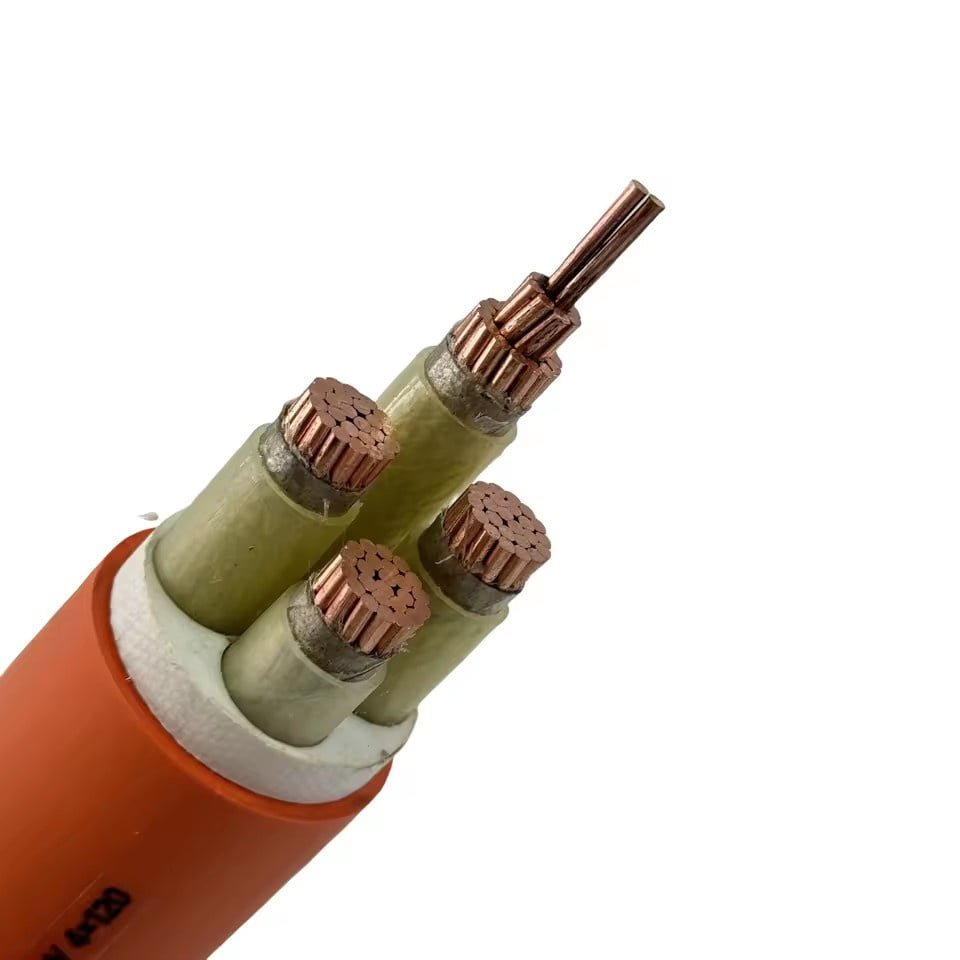
These two categories are frequently confused, and mixing them up on a project can mean failing a building inspection or, worse, contributing to casualties in a fire event. Flame-retardant cables (IEC 60332-1) self-extinguish — they won’t propagate flame once the ignition source is removed. Fire-resistant cables (IEC 60331) go further: they maintain circuit integrity at 750–1,000°C for a defined duration, typically 30–120 minutes depending on the standard and product classification. NHXH and WDZA-YJY are fire-resistant LSZH types. Fire-resistant cables are mandatory for emergency lighting circuits, fire alarm wiring, elevator supply, and smoke extraction fans in virtually every modern building code. Low-smoke zero-halogen (LSZH) insulation reduces toxic gas and corrosive smoke output — relevant not just for occupant safety but for protecting sensitive equipment in the same space.
PV DC Cables
Utility-scale solar has turned PV DC cable into a meaningful procurement category. TUV 2 Pfg 1169 and UL 4703 are the dominant certifications. These cables operate at up to 1,500 V DC — technically low voltage by IEC classification — in outdoor string and combiner-box wiring exposed to UV, ozone, moisture cycling, and in some climates, significant temperature swings between night and midday. The insulation compound needs genuine UV and ozone resistance, not just a standard outdoor rating. Design life targets are typically 30 years; cheaper non-certified cable used to cut BOM cost on a solar EPC project is a long-term reliability gamble on a 25-year power purchase agreement.
Quick-Reference: Cable Types by Application
| Cable Type | Typical Voltage Rating | Insulation | Armoring Option | Representative Applications |
|---|---|---|---|---|
| NYY / NAYY | 0.6/1 kV | PVC | Optional STA/SWA | Underground mains, substation feeders, building distribution |
| N2XY / YJV / YJLV | 0.6/1 kV | XLPE | Optional AWA/SWA | Industrial feeders, MV/LV transformer LV side, high-temp environments |
| KVVP / KYJVP | 450/750 V or 0.6/1 kV | PVC or XLPE | Screened (overall or individual) | PLC wiring, MCC signal cables, relay panel interconnects |
| H07RN-F / EPR trailing | 450/750 V | Rubber / EPR | None (flexible) | Cranes, hoists, festoon systems, portable tools |
| NHXH / WDZA-YJY | 0.6/1 kV | LSZH fire-resistant | Optional | Emergency lighting, fire alarm, evacuation system circuits |
| PV DC (TUV 2 Pfg 1169 / UL 4703) | Up to 1,500 V DC | XLPE/LSZH UV-stabilized | None typically | Solar string wiring, combiner box connections, rooftop and utility-scale PV |
The table is a starting point, not a complete specification. Armoring selection, number of cores, conductor material, and installation method all feed into the final call — and those decisions depend on the specific route, environment, and fault protection design of the system being built.
Key International Standards That Govern Low Voltage Cable Design, Testing, and Approval
If you’ve ever submitted a cable submittal package to a project engineer only to have it rejected because the test reports cited the wrong standard, you already understand why this matters. Standards aren’t paperwork — they’re the shorthand language that lets a factory in Shandong, a procurement desk in Rotterdam, and a site foreman in Lagos all agree on exactly what a cable must do before anyone pulls it through conduit.
IEC 60502-1: The Foundation Document
IEC 60502-1 covers power cables with extruded insulation rated up to 1 kV. It defines permissible construction geometries, insulation and sheath thicknesses, dimensional tolerances, and — critically — the mandatory type-approval test sequence. Type approval under this standard means a specific cable construction has been independently tested and confirmed against the full test matrix, not just a factory declaration.
The tests that most frequently trip up manufacturers during audits are the voltage withstand test (3.5 kV AC applied for 5 minutes on a 0.6/1 kV cable, with zero breakdowns permitted), conductor DC resistance measured at 20 °C, insulation resistance after immersion, and the cold-bend test, which varies by insulation material and matters more than buyers realize in northern European and high-altitude installations. Any cable claiming IEC 60502-1 compliance should come with a full type-test report — not just a certificate number. Ask for the actual test report and check the construction it was issued against matches what you’re receiving.
IEC 60228: Getting Conductor Class Right Before the Termination Crew Arrives
This one causes avoidable site rework. IEC 60228 defines conductor classes and their maximum resistance values. Class 2 is a stranded but relatively rigid conductor used in fixed installations. Class 5 is the fine-wire flexible conductor you need for control panels, machine tools, or anything that flexes during service. A Class 5 conductor requires different compression lugs and ferrules than Class 2 — wrong hardware means either a cold joint or a conductor pulled back into the lug under vibration. Procurement teams specifying large orders should confirm the conductor class on the purchase order, not assume it from the cross-section alone.
Regional Equivalents and Cross-Reference
| Market | Primary Standard | Notes |
|---|---|---|
| International / Export | IEC 60502-1, IEC 60228 | Baseline for most project specs |
| United Kingdom | BS 6346, BS 7671 | BS 7671 governs installation wiring rules |
| Germany / EU | DIN VDE 0276, DIN VDE 0295 | Close alignment with IEC; VDE mark adds value |
| China (domestic) | GB/T 12706, GB/T 9330 | Jinda’s domestic production governed here |
| North America | UL 83, UL 44, NEC | UL listing required; NEC governs installation method |
| Australia / New Zealand | AS/NZS 5000 | Separate approval path; don’t assume IEC certs transfer |
Jinda’s export documentation covers IEC and CE-harmonized EN standards across the low voltage range, which simplifies customs clearance and project engineer approval in most non-North American markets.
Fire Performance: Four Standards, Not One
This is where a lot of spec writers go wrong. A cable marketed as “LSZH fire-resistant” must satisfy four distinct standards simultaneously. IEC 60332 series covers flame propagation — both single-cable and bunched-cable burning behavior. IEC 60331 tests circuit integrity under fire conditions, meaning the cable must continue to function for a defined period while burning. IEC 61034 measures smoke density. IEC 60754 measures halogen content in combustion gases. Each standard tests a different failure mode. A cable can pass IEC 60332-1 (won’t spread flame along a single cable) and still emit dense, toxic smoke — so it doesn’t qualify as LSZH unless it also satisfies 61034 and 60754. Specifiers writing tender requirements should list all applicable fire codes explicitly; “flame retardant” and “LSZH fire-resistant” are not interchangeable.
Certification Marks and What They Actually Guarantee
CCC (China Compulsory Certification) is mandatory for cables sold into the Chinese domestic market under product categories defined by the government catalog. CE marking in Europe confirms conformity with harmonized EN standards — it opens the EU market but is a self-declaration backed by documentation, not always a third-party tested mark. KEMA or DNV-GL type approval carries more weight for marine and offshore applications because those bodies conduct independent witnessed testing. SGS, Bureau Veritas, and TÜV test reports are third-party laboratory results — valuable supporting evidence, but only as good as the construction they were run on.
A cable bearing a CE mark has been independently tested by a notified body.False
CE marking for most low voltage cable categories is a manufacturer's declaration of conformity against harmonized EN standards. Third-party notified body involvement is only mandatory for certain regulated categories. Buyers wanting independent test evidence should request laboratory reports from SGS, Bureau Veritas, TÜV, or equivalent.
In practice, project engineers on international tenders typically require IEC type-test reports plus any country-specific certification. Having both in your submittal package from the outset avoids the approval-cycle delay that pushes cable deliveries past the installation window — which, on a compressed project schedule, can cost far more than the cable itself.
How to Select the Right Low Voltage Cable: A Step-by-Step Specification Checklist
Getting the selection wrong costs real money. A cable undersized by one cross-section step runs hot, degrades insulation faster, and trips protective devices under peak load. Oversized cable wastes copper and inflates installed cost. The checklist below is the sequence experienced installation engineers actually follow — not a textbook summary, but a working order of operations.
Step 1 — Define the Electrical Load and Size the Conductor
Start with full-load current. For three-phase loads: I = P / (√3 × V × PF × η). A 75 kW motor at 0.85 PF and 0.93 efficiency on a 400 V system pulls roughly 137 A — not 125 A, not 150 A. Use the real numbers.
Pull the base current-carrying capacity from IEC 60364-5-52 tables for your installation method (clipped direct, in conduit, buried, free air — each has its own column). Then apply derating factors before you commit to a cross-section. Ambient temperature above 30°C knocks capacity down; at 45°C with PVC insulation the correction factor is approximately 0.87. Grouping cables in a duct or tray together can reduce capacity by 30–40% depending on how tightly they’re packed. In practice, a busy cable tray with six or eight circuits touching can force you up two conductor sizes compared to a single isolated run.
Step 2 — Check Voltage Drop Over the Full Run
Current-carrying capacity alone doesn’t size the cable on long runs. IEC 60364-5-52 and BS 7671 both cap voltage drop at 3% for lighting circuits and 5% for power circuits measured from the installation origin.
Use: ΔV = (√3 × I × L × (R cosφ + X sinφ)) / 1,000
Worked example: 100 A load, 50 m run, 35 mm² copper, cosφ = 0.85. At 70°C, R ≈ 0.627 Ω/km, X ≈ 0.069 Ω/km. ΔV = (1.732 × 100 × 0.05 × (0.627 × 0.85 + 0.069 × 0.527)) / 1 ≈ 5.1 V, or about 1.3% on 400 V. Acceptable. Stretch that same run to 150 m and you’re at roughly 3.8% — still within the 5% power limit, but worth noting in your calculations file. If voltage drop governs rather than current capacity, move up to 50 mm² and recalculate. It happens more often than engineers expect on long motor feeders in large factories.
Step 3 — Verify Short-Circuit Thermal Capacity
The conductor must survive the fault current for however long the upstream breaker or fuse takes to clear. The adiabatic equation: S = I × √t / k, where k = 115 for PVC-insulated copper and 143 for XLPE-insulated copper. If a 100 A circuit has a 10 kA prospective fault current and the breaker clears in 0.1 s, minimum conductor size = 10,000 × √0.1 / 115 ≈ 27.5 mm². A 35 mm² cable passes; a 16 mm² does not, even if current capacity and voltage drop looked fine.
Operational warning: Skipping this step is common on lightly loaded branch circuits. A small cross-section that handles normal current comfortably can still fail catastrophically under fault conditions if the upstream device is slow to clear.
The adiabatic equation S = I × √t / k is the standard method referenced in IEC 60364-4-43 for verifying conductor short-circuit thermal withstand.True
IEC 60364-4-43 clause 434.5 specifies this adiabatic formula for checking conductor thermal withstand under short-circuit conditions, with tabulated k values for common insulation and conductor material combinations.
Step 4 — Match Construction to the Mechanical Environment
| Installation Environment | Recommended Construction | Notes |
|---|---|---|
| Direct buried in soil | SWA or STA armored, XLPE | Sand bed, cover tiles; depth per local code |
| Cable tray, indoor | Unarmored XLPE, LSZH sheath | Check tray fill ratio |
| Moving machinery / flexing | Class 5 fine-wire conductor, EPR or rubber insulation | Avoid solid or Class 2 for repeated flex |
| Outdoor above-ground | UV-resistant PE or LSZH outer sheath | Black sheath typically more UV-stable than grey |
| Underground duct/conduit | XLPE, unarmored acceptable | Pulling tension limit governs drum length |
Armoring adds protection but also adds weight and minimum bend radius. On a tight conduit run through a machine room, that matters.
Step 5 — Confirm Fire, Environmental, and Area Classifications
A public building or transport tunnel usually demands LSZH (low smoke zero halogen) sheath and insulation — sometimes halogen-free throughout every layer, not just the outer sheath. Marine installations require Lloyd’s or Bureau Veritas type approval. Hazardous areas (ATEX Zone 1/2 or IECEx-rated installations) need cables certified for the specific gas group and temperature class. Food-processing facilities often add requirements for rodent resistance or cleanability of the outer sheath. Miss any of these and the cable that passed every electrical calculation still fails the project audit.
Step 6 — Write a Complete Procurement Specification
Vague RFQs cause substitution errors and delayed approvals. A clean spec line for a procurement package to Jinda or any reputable supplier should read:
- Conductor: copper, Class 2 (or Class 5 for flexible), cross-section in mm²
- Number of cores and identification method (IEC 60446 color coding or project-specific standard)
- Insulation: XLPE or PVC, voltage rating (e.g., 0.6/1 kV per IEC 60502-1)
- Inner bedding and armoring type (SWA, STA, or unarmored)
- Outer sheath: PVC, LSZH, or PE with UV stabilization
- Required certifications: IEC test reports, KEMA, BASEC, UL, or other project-mandated approvals
- Drum length and tolerance (±5% is common; tighter tolerances cost more)
- Delivery format: wooden drum, steel drum, or coil — and whether returnable drums are expected
Sending this level of detail upfront cuts back-and-forth by at least half and makes cross-supplier comparison straightforward. In practice, procurement teams that skip the armoring specification or leave sheath material open to supplier discretion end up with mismatched deliveries that stall installation crews.
Installation Best Practices That Protect Low Voltage Cable Performance and Service Life
Correct specification gets you the right cable on the drum. What happens between the drum and the termination point determines whether that cable lasts 30 years or fails inside five. In my experience, most field failures trace back not to a bad product but to installation shortcuts that nobody flagged at the time.
Minimum Bending Radius — Where Insulation Cracking Starts
Armored low voltage cables require a minimum bend radius of 8–12 times the overall cable diameter during pulling and at final installation; the exact multiplier depends on armor type and the number of cores. Single-wire armored (SWA) constructions sit toward the higher end of that range. Flexible cables are more forgiving — 4–6 times the overall diameter per IEC 60502-1 Annex B — but that tolerance disappears fast if the cable is cold (below about 5°C, PVC stiffens significantly, and what looks like a gentle bend can actually stress the insulation). Violate the minimum radius and you don’t always see immediate failure. What you get is a deformed armor layer pressing against cracked insulation, a micro-void that absorbs moisture, and a high-resistance hot spot that shows up on thermal imaging two years later after the insulation carbonizes. By then nobody remembers the pull.
Pulling Tension and Sidewall Pressure
Pulling tension on copper conductors should not exceed 50 N/mm² of conductor cross-sectional area. For a 3-core 95 mm² copper cable, that works out to roughly 14,250 N maximum — and most site crews eyeballing the capstan have no idea they’re near that limit. Aluminum conductors are weaker in tension; the allowable figure drops to around 30–35 N/mm² depending on alloy and stranding class, so substituting aluminum on a long duct run without recalculating tension is a genuine risk.
Sidewall pressure at conduit bends must stay below 3,000–5,000 N/m depending on cable construction, with armored cables and tightly jacketed types at the lower end of tolerance. The formula is straightforward: sidewall pressure equals pulling tension divided by bend radius in meters. A 10,000 N pull through a 0.5 m radius bend produces 20,000 N/m — four to six times the safe limit. Exceed this and armor wires can indent the insulation without leaving any visible external damage. Most cable manufacturers will void the warranty on a cable that was pulled without a recorded tension log.
Conduit Fill Ratios
NEC and IEC guidance both cap conduit fill at 40% of the internal conduit cross-sectional area for three or more cables. The table below gives practical working numbers for common conduit sizes.
| Conduit ID (mm) | Internal Area (mm²) | 40% Fill Area (mm²) | Max cables: 4 mm² (approx. 8 mm OD) | Max cables: 16 mm² (approx. 14 mm OD) | Max cables: 50 mm² (approx. 22 mm OD) |
|---|---|---|---|---|---|
| 20 | 314 | 126 | 2 | 0 | 0 |
| 32 | 804 | 322 | 6 | 2 | 0 |
| 50 | 1,963 | 785 | 15 | 5 | 2 |
| 75 | 4,418 | 1,767 | 35 | 11 | 4 |
| 100 | 7,854 | 3,142 | — | 20 | 8 |
| 150 | 17,671 | 7,068 | — | — | 18 |
Cable OD figures here are approximate midpoints for common PVC/XLPE constructions — always verify against the actual drum datasheet before committing to conduit sizing on a project.
Termination and Jointing — the Hidden Failure Hotspot
Roughly 30–40% of low voltage cable failures in service originate at terminations, not along the cable run itself.
Improper terminations account for an estimated 30–40% of low voltage cable failures in serviceTrue
This range is consistently cited in cable industry failure analysis studies and aligns with field inspection data from distribution network operators; root causes include incorrect lug sizing, undertorquing, and mismatched metals at the contact interface.
Use tin-plated copper compression lugs on copper conductors — unplated lugs oxidize at the barrel interface and creep resistance rises over years of thermal cycling. For aluminum conductors, bi-metal lugs (aluminum barrel, copper palm) are not optional; they’re the only way to manage the electrochemical potential difference and the differential thermal expansion between aluminum and copper bus. Torque values from IEC 60999 are specific to connector size and must be followed with a calibrated torque wrench, not estimated by feel. Undertorquing is more common than overtorquing in practice; a loose lug on a 400 A feeder will arc-track within months.
Heat-shrink joint systems are more forgiving on irregular surfaces and tolerate some installer variation; cold-shrink systems are faster in confined spaces and perform better in low ambient temperatures where a heat gun is impractical. Either is acceptable for most LV applications, but cold-shrink tends to cost 15–30% more per joint depending on supplier and cable size.
Direct Burial Requirements
Minimum cover depth is typically 600 mm under footpaths and landscaped areas, 900 mm under roadways — though local codes vary and some specifications require 1,200 mm under roads carrying heavy vehicle loads. Getting this wrong means either a compliance failure or, worse, a mechanical strike during future groundwork.
Warning tape in a contrasting color (usually yellow or red, printed with “ELECTRIC CABLE BELOW”) goes into the trench 150–300 mm above the cable, not at ground level. Route markers at spacing required by the local utility — often every 50 m and at every change of direction. Before you close the trench, conduct an insulation resistance test at 500 V DC on each core to screen earth to verify the drum hasn’t been damaged during handling or laying. It takes ten minutes per drum and has saved more than a few projects from burying a damaged cable only to excavate again three weeks later.
Thermal Management in Cable Trays and Ducts
PVC-insulated cables are rated for a maximum conductor operating temperature of 70°C; XLPE and EPR sit at 90°C. Those ratings assume the cable is derated properly for ambient conditions and grouping factors. In a cable tray with eight or ten cables bundled tightly — a common sight in any industrial plant — derating factors can reduce allowable current by 30–50% compared to a single cable in free air.
The Arrhenius degradation model gives the underlying reason to take this seriously: for every 10°C above the rated operating temperature, insulation aging rate roughly doubles and service life halves. A PVC cable running at 80°C continuous instead of 70°C doesn’t just run slightly hotter — it ages at approximately twice the rate. In a plant where that cable feeds a critical production line, you’re cutting the expected service life from perhaps 25–30 years down to 12–15, and the failure will show up at the worst possible time. Leaving 20–25% of spare capacity in cable trays at commissioning is not wasted money; it’s future maintenance you avoid paying for.
Understanding Low Voltage Cable Datasheets and Drum Markings: A Buyer’s Field Guide
Specification errors rarely happen at the design stage. They happen in the receiving bay, when a procurement officer accepts a drum that looks right but isn’t. Knowing how to read a drum label and a test certificate takes about thirty minutes to learn and can prevent weeks of site dispute.
What Every Drum Label Must Show
IEC 60829 governs drum marking requirements. A compliant drum label — including labels on Jinda drums shipped to international projects — should carry all of the following: manufacturer name and contact information, the full cable designation code, voltage rating (both Uo/U), conductor material and stranding class, cross-section and number of cores, manufactured length, gross weight of the drum, and a direction-of-rotation arrow showing which way to unwind without kinking.
That last item gets ignored more often than it should. Unwind a drum backwards on a tight conduit pull and you can introduce a twist-induced insulation stress that won’t show up until the cable has been energized for six months.

Decoding the Cable Designation Code
Take a real procurement document entry: 4×95 mm² XLPE/SWA/LSZH 0.6/1 kV.
Parsed field by field: 4×95 mm² means four cores, each with a 95 mm² conductor cross-section. XLPE is cross-linked polyethylene insulation. SWA is steel wire armor. LSZH is the outer sheath material — low-smoke zero-halogen compound, which matters in tunnels, public buildings, and offshore modules where toxic combustion gases are a life-safety concern. 0.6/1 kV is the rated voltage: 0.6 kV phase-to-earth, 1 kV phase-to-phase. This is the standard low voltage classification under IEC 60502-1.
If the drum label reads PVC where your spec says LSZH, that is not an acceptable substitution. PVC and LSZH have different smoke and halogen emission profiles, different flame propagation behavior, and often different temperature ratings. Reject it at goods-in, not after installation.
Reading a Test Certificate Without Getting Fooled
A proper routine test certificate for LV power cable should cover, at minimum: conductor DC resistance (verified against IEC 60228 tables for the declared cross-section and class), high-voltage withstand test (typically 3.5 kV AC for 5 minutes on 0.6/1 kV cable), and insulation resistance. For XLPE insulation, the hot set test — measuring elongation under load at 200 °C — is a type test that confirms the degree of cross-linking. If a supplier provides a certificate missing the hot set result for XLPE cable, you cannot confirm the insulation is properly cured.
Watch for certificates that list tests as “refer to type test report.” That means the specific drum in your order was not individually tested for those parameters. Routine tests and type tests are not interchangeable. Routine tests happen on every production length; type tests happen on a representative sample, sometimes years before your order was manufactured.
IEC 60502-1 distinguishes between routine tests performed on every cable length and type tests performed on representative samples; a test certificate covering only type tests does not confirm the specific production batch meets all parameters.True
IEC 60502-1 Clause 18 defines routine tests as mandatory for every drum, while Clause 19 defines type tests as qualification tests on a sample. Substituting one for the other is a common documentation gap that procurement teams should challenge explicitly.
Reel Length Tolerances: The Hidden Shortfall
IEC 60502-1 permits a manufacturing length tolerance of ±5%. On a 500 m order, that means a supplier can legally deliver anywhere from 475 m to 525 m. For a single building floor this might not matter. For a large substation project where you’ve calculated cutting schedules to the metre, a 25 m shortfall across multiple drums can create a genuine installation problem — emergency re-orders, delays, expediting costs.
The fix is simple: specify minimum net delivered length in the purchase order, not nominal length. And measure with a cable counter off the drum before cutting, not by trusting the label. Drum labels can be wrong, especially on redrummed or rejointed stock.
Factory Acceptance Testing and Third-Party Inspection
For orders above roughly 50–100 km total length (the threshold depends on project risk and budget), witnessed factory acceptance testing is worth the travel cost. At Jinda’s production facilities, witnessed FAT for LV cable typically includes conductor resistance checks, voltage withstand on sample lengths, dimensional verification of insulation and sheath thickness, and review of raw material batch certificates.
For buyers who cannot travel, SGS and Bureau Veritas both offer pre-shipment inspection services that include drum-level verification against shipping documents. Specify this in your supply contract before order placement, not after the cable has left the factory. Getting an inspector on-site post-production is always harder and sometimes impossible once drums are in a container.
Three Field Checks That Catch the Most Common Fraud
Conductor substitution — aluminum sold as copper, or a smaller cross-section than specified — is the fraud most likely to survive receiving inspection without active verification. A digital micrometer on a stripped conductor end takes under two minutes. Compare the measured diameter against the theoretical diameter for the declared cross-section and stranding class; tables are in IEC 60228. Significant deviation warrants rejection and formal claim.
Armor wire diameter reduction is subtler. Pull a short length of armor wire off the cable end and mic it. A 95 mm² SWA cable has a specified armor wire diameter in the construction drawing; undersized wire means reduced mechanical protection and reduced short-circuit current carrying capacity of the armor.
Sheath compound quality is harder to verify in the field, but a basic halogen test strip (available from any cable testing kit supplier) can distinguish LSZH from PVC within minutes. If your spec requires LSZH and the sheath tests positive for halogen, the cable is not what you ordered. In practice, experienced buyers on projects in the Middle East and Southeast Asia run this check as standard — not because reputable manufacturers cut corners, but because the supply chain is long and redrumming happens.
Global Procurement Considerations When Sourcing Low Voltage Cable from China
China’s share of global LV cable production sits somewhere in the 35–40% range by volume, and that figure hasn’t shrunk meaningfully in over a decade. The reasons aren’t mysterious: vertically integrated supply chains that run from copper rod casting and aluminum rolling through extrusion and final testing, large-scale production lines that run continuously rather than in campaign batches, and a labour and energy cost structure that — even after recent increases — remains competitive on commodity constructions. When a contractor in the Middle East or a utility in Southeast Asia prices out 50,000 m of 4×70 mm² copper XLPE SWA, the landed cost from a Shandong factory versus a European mill is often the deciding factor.
For a rough anchor: 4×70 mm² copper XLPE SWA cable typically trades in the range of USD 18–26 per metre ex-works from established Chinese manufacturers, depending heavily on the copper price at order date, armour type (galvanised steel wire vs. double-wire), and sheath specification. Move up to 4×240 mm², and you’re looking at roughly USD 55–80 per metre ex-works under similar conditions. These are not catalogue prices — they move with the LME copper price, sometimes significantly week to week, so any serious procurement should lock in a price against a declared copper rod index rather than a fixed per-metre rate.
Lead Times and What Drives Them
Standard catalog constructions — common cross-sections, standard black or grey HDPE outer sheaths, conventional core counts — will typically ship ex-works within 2–4 weeks for orders above roughly 2,000 kg from a manufacturer with the construction already in their standard program. That assumes raw material is in stock, which for copper rod is usually true at larger factories but worth confirming in writing, especially during periods of tight copper supply.
Custom work takes longer. Non-standard sheath colours (orange for direct burial in some markets, red for fire circuits per certain national codes), unusual core counts like 7-core or 12-core for specialised control applications, or specialty insulation compounds like low-smoke zero-halogen (LSZH) will generally push lead time to 4–8 weeks. MOQs for these constructions are usually 500–1,000 m per individual type — below that, most factories won’t tool up. In practice, if you’re ordering mixed specialty constructions for a complex project, combining them into a single purchase order improves your negotiating position on both price and lead time.
Shipping Logistics — Heavier Than People Expect
LV cable drums are genuinely heavy freight. A 500 m drum of 4×240 mm² copper SWA will weigh somewhere between 1,800 and 2,200 kg depending on drum construction and armour specification. This matters because drums this size don’t palletise neatly into standard 20-foot containers — they typically ship as breakbulk or on flat-rack containers, which carry different freight rates and port handling charges than conventional box containers. Budget 30–45 days sea freight to European ports from Qingdao or Tianjin, and similar or slightly longer for US East Coast destinations.
One detail that catches buyers out: wooden cable drums must carry an ISPM 15 phytosanitary treatment stamp (heat-treated timber) for import into the EU, Australia, the US, and most other markets. Missing this on arrival means fumigation delays or destruction of the packaging — neither is cheap. Confirm this requirement explicitly with your supplier before drums are built.
Trade Documentation Checklist
Getting documentation right upfront prevents delays at destination customs that can run into weeks. The standard set for a Chinese LV cable export shipment should include:
| Document | Key Detail to Verify |
|---|---|
| Commercial invoice | HS code 8544.49 for insulated conductors; declared unit of measure (per metre or per kg — align with LC terms) |
| Packing list | Individual drum numbers, lengths per drum, gross/net weights |
| Certificate of origin | Form E for ASEAN preferential duty; EUR.1 or equivalent for applicable bilateral agreements |
| Material test certificates | Conductor resistance per IEC 60228, insulation resistance, voltage test results — per drum or per batch |
| CCC certificate copy | Required if cables are also sold into the Chinese domestic market; useful as a baseline QA reference |
| Third-party inspection report | Required by many LC terms and most public infrastructure projects |
Quality Assurance on Large Orders
Don’t rely solely on mill test certificates for critical infrastructure purchases. At minimum, request a pre-shipment inspection (PSI) covering visual examination, dimensional checks against the approved datasheet, and conductor resistance measurement per IEC 60228 — this catches substituted conductor material and undersized cross-sections, which remain the most common non-conformances in commodity cable procurement. For larger projects — substations, industrial plants, anything where a cable failure causes extended outage — a witnessed factory acceptance test (FAT) at the production facility is worth the travel cost.
Jinda operates five production bases across China with a combined 470,000 m² of manufacturing space and has shipped to customers in over 50 countries.True
This figure is consistent with the manufacturer's documented facilities and international shipping activity across multiple continents.
Jinda’s export operation is set up to produce to IEC, BS, DIN, and GB standards on the same production lines — which matters when a single project draws specifications from more than one national framework, something that’s common in infrastructure work across Africa and Southeast Asia. Full traceability from copper rod input to finished drum labelling is maintained, which supports the documentation chain that letter-of-credit transactions and third-party inspection regimes require.
The honest caveat: no factory, regardless of size or certification, should be bought from blindly on first order. Sample cables, witnessed tests, or at minimum a thorough reference check from a project in a similar market are reasonable due diligence on any order above roughly USD 100,000 in value.
Frequently Asked Questions About Low Voltage Cables
These are the questions that come up repeatedly — on tender reviews, at goods-in inspection, during commissioning, and occasionally in post-failure investigations. Straight answers follow.
What is the difference between low voltage and extra-low voltage (ELV) cables?
ELV covers circuits operating below 50 V AC or 120 V DC, per IEC 60038. Telecommunications cabling, Cat5e/Cat6 data runs, LED driver wiring, and safety-circuit loops all fall here. LV starts at 50 V AC and runs to 1,000 V AC. The construction requirements are fundamentally different — ELV cables are built around signal integrity, flexibility, and low capacitance, not insulation thickness rated for fault-level voltages. Connecting an ELV data cable into a 230 V circuit won’t just fail; it will fail dangerously. They are not interchangeable, and no derating factor makes them so.
Can I use a 0.6/1 kV rated cable on a 400 V three-phase system?
Yes, and this is actually the correct, standard choice for European and international 50 Hz distribution. The dual rating 0.6/1 kV means 600 V phase-to-earth (U₀) and 1,000 V phase-to-phase (U). A 400/230 V TN-S or TN-C-S system sits well inside both limits — 230 V phase-to-earth against the 600 V U₀ rating, 400 V phase-to-phase against the 1,000 V U rating. There is comfortable headroom for transient overvoltages. This voltage designation is so universal for LV power work that when a datasheet simply says “1 kV cable,” a 400 V distribution system is exactly the application it was designed for.
What does LSZH mean, and when is it mandatory?
LSZH — Low Smoke Zero Halogen — describes a cable whose sheath and insulation, when burned, produce minimal smoke opacity and release no halogenic acid gases such as HCl. Standard PVC, by contrast, releases dense black smoke and toxic HCl that corrodes electronics, destroys switchgear contacts, and — critically — reduces evacuation visibility. LSZH is mandatory or strongly enforced in enclosed public spaces: metro tunnels, airport terminals, hospitals, data centers, and any building where dense smoke or acid gas would impede escape or cause secondary equipment damage. In practice, many European and Middle Eastern project specifications now default to LSZH for all indoor LV wiring regardless of occupancy category, simply to remove ambiguity on site.

How long does a properly installed low voltage cable last?
IEC standards set a design service life of 30 years under rated conditions. XLPE-insulated cables routinely reach 40–50 years in moderate climates with good installation practice. PVC-insulated cables can develop issues earlier — plasticizer migration causes the insulation to harden and crack, especially in environments where conductor temperatures regularly run at the upper end of the 70°C rating. In hot industrial environments I have seen PVC cables become brittle inside 15–18 years. Regular thermal imaging surveys and trended insulation resistance measurements (not just pass/fail megger tests) are the most reliable way to catch end-of-life before it becomes an unplanned outage.
Is aluminum conductor cable a safe choice for LV power distribution?
Yes, when correctly specified and terminated. Cables like 4×240 mm² NAYY or YJLV are standard in utility distribution networks globally, and for good reason — aluminum is roughly one-third the weight and cost of equivalent copper. The requirements are specific: bi-metal compression lugs, anti-oxidant jointing compound, and higher terminal torque values than copper. Where aluminum gets into trouble is below 16 mm² cross-section. Small-diameter aluminum is susceptible to fatigue cracking at connection points subject to any vibration or repeated flexing. That is why building wiring codes in most countries prohibit aluminum below 16 mm² for fixed installations, and why it never appears in flexible cable designs.
Aluminum conductors below 16 mm² are generally avoided in building wiring due to fatigue cracking risk at connections.True
IEC and most national wiring regulations restrict aluminum conductors in building installations to 16 mm² and above. Small cross-section aluminum is mechanically vulnerable to cracking under repeated micro-movement at terminals, which leads to high-resistance connections, arcing, and fire risk.
What is the maximum run for a 2.5 mm² copper cable on a 230 V / 16 A circuit?
Using a 3% voltage drop limit — 6.9 V on a 230 V circuit — and the IEC 60228 Class 2 resistance of roughly 7.41 mΩ/m at 70°C, the maximum single-way cable length for a 16 A unity power factor load works out to around 23–25 m. That figure tightens if you stack in correction factors for grouping or elevated ambient temperature. At lower actual load currents the permissible distance scales up proportionally. Longer runs on 2.5 mm² are common in practice, but only because the circuit rarely draws its rated 16 A continuously — sizing for actual design current rather than the protective device rating is better engineering.
How do I verify that a cable labeled as copper is not copper-clad aluminum (CCA)?
Three checks, none of them expensive. Cut the conductor cleanly and inspect the cross-section under reasonable light — CCA shows a clearly visible silver-coloured aluminum core inside a thin copper skin, usually obvious to the naked eye. Measure conductor resistance with a calibrated micro-ohmmeter and compare to IEC 60228 Class 2 maximum resistance values; CCA conductors typically exceed the copper limit by around 55–65% because aluminum’s resistivity is roughly 1.6 times higher. Finally, request the material test certificate showing copper rod input lot numbers and chemical composition — a legitimate manufacturer can produce these without hesitation. If there is any delay or reluctance on that last point, treat it as a red flag.