A misapplied residential cable in an industrial setting doesn’t just violate code — it fails. Sometimes within weeks. The insulation breaks down under continuous high-temperature loading, the conductor cross-section can’t sustain the ampacity the process demands, and when that circuit trips or burns, the downstream cost isn’t just a replacement spool of wire. It’s unplanned downtime, scrapped product, a potential arc-flash incident, and an insurance conversation nobody wants to have. Procurement managers who spec cable purely on unit price without distinguishing wiring class are, in effect, deferring those costs to the plant floor.
Residential wiring and industrial wiring differ in voltage class, conductor sizing, insulation grade, mechanical protection, and installation standards. Residential branch circuits typically operate at 120/240 V or 230 V AC with conductors from roughly 1.5 mm² to 10 mm², while industrial systems run at 480 V, 600 V, or higher three-phase voltages and routinely require conductors from 1.5 mm² up to 630 mm² or beyond, sized for continuous duty at up to 80% of rated ampacity.
What makes this comparison genuinely useful for engineers isn’t a checklist of voltage numbers — it’s understanding why those differences exist, what happens when the wrong product gets installed, and how to read a cable specification so you’re not relying on the vendor to catch the mismatch for you.
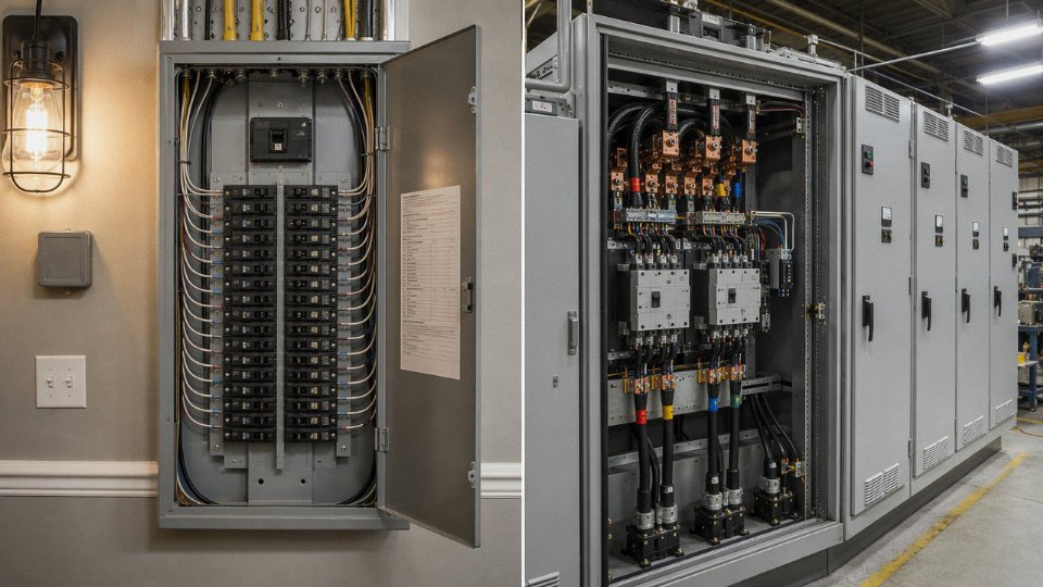
Voltage Classes and Circuit Configurations That Separate Home Wiring from Factory Wiring
Walk into a residential panel in North America and you’ll find a 120/240 V split-phase setup — two 120 V legs derived from a center-tapped transformer, feeding single-phase branch circuits at 15 A or 20 A. Most loads in that house top out well under 10 kW. A dryer or range might pull 30–50 A at 240 V, but that’s about as demanding as residential wiring gets. European and much of Asian residential construction uses single-phase 230 V (nominally 220–240 V depending on national standard), same fundamental architecture, just without the split-phase center tap. The panel layout changes; the underlying logic doesn’t.
A factory is a completely different electrical universe.
Industrial facilities routinely distribute power at 380 V, 480 V, or 600 V three-phase — and larger plants run medium-voltage (MV) switchgear at 6 kV, 10 kV, or up to 35 kV inside the fence before stepping down to utilization voltage at motor control centers or unit substations. The three-phase topology exists for a hard physical reason: rotating machinery is far more efficient and mechanically smoother on balanced three-phase power. A 75 kW induction motor fed from a 480 V three-phase wye source draws roughly 95–110 A per phase under full load — try to feed that from a residential split-phase panel and you’d need conductors and breakers sized for something closer to a small substation.
Delta vs. Wye — and Why It’s Not Just Academic
The wye (star) configuration gives you a neutral conductor and two usable voltages: line-to-neutral (e.g., 277 V on a 480 V wye system) and line-to-line (480 V). That 277 V line-to-neutral is why you see it feeding fluorescent and LED high-bay lighting in warehouses — no step-down transformer needed. Delta configurations have no neutral and are common for motor-only loads or in older industrial installations. For cable selection, delta systems mean every conductor in that circuit must be rated for full line-to-line voltage, no exceptions. A cable sized for line-to-neutral voltage on a delta system is a latent fault waiting to happen, especially under ground-fault conditions where the unfaulted phases can see elevated voltage stress.
How Voltage Class Drives Insulation Decisions
Insulation thickness isn’t cosmetic. It’s a direct function of the dielectric stress the material must withstand continuously, and the safety margins required by standards like IEC 60502 or UL 44. Below is a working reference for procurement and design teams:
| Voltage Tier | Typical Application | Common Conductor Size Range | Minimum Insulation Voltage Rating |
|---|---|---|---|
| 120/240 V single-phase | Residential branch circuits | 1.5 mm² – 10 mm² | 300/500 V or 450/750 V |
| 380–480 V three-phase | Industrial motors, HVAC, MCC feeds | 4 mm² – 185 mm² | 0.6/1 kV |
| 600 V three-phase | North American industrial, heavy equipment | 6 mm² – 240 mm² | 0.6/1 kV (600 V rated) |
| 6 kV–35 kV medium voltage | In-plant primary distribution, large drives | 35 mm² – 630 mm²+ | 3.6/6 kV up to 20.8/35 kV |
Higher voltage ratings mean thicker insulation walls, which directly increases cable outer diameter. That cascades into conduit fill calculations, cable tray loading, and bend radius requirements — all of which need to be engineered before you pull a single meter of cable.
Using a 300/500 V rated cable on a 480 V three-phase industrial circuit is a code violation that also creates real electrocution and fire risk under fault conditions.True
The insulation dielectric withstand of a 300/500 V cable is not designed for the sustained or transient voltage stress seen on a 480 V system, particularly in delta configurations or during ground faults where phase-to-ground voltage can rise significantly. Standards including NEC and IEC 60502 explicitly prohibit this mismatch.
Procurement managers sometimes order cable by conductor size alone, treating voltage rating as secondary. That’s the wrong priority order. A 35 mm² conductor in a 0.6/1 kV jacket and a 35 mm² conductor in a 6/10 kV jacket are not interchangeable — they’re different products with different material costs, different installation requirements, and very different failure modes if misapplied. The conductor cross-section tells you about ampacity. The voltage rating tells you whether the cable survives being energized at all.
Conductor Sizing, Ampacity, and Load Duty Cycle: How Demand Profiles Differ Radically
The wire gauge in your kitchen wall and the cable feeding a 200 kW compressor motor are both “electrical conductors,” but treating them as variations of the same thing is a mistake that shows up as nuisance trips, insulation failures, or worse.
Residential Load Profiles: Diversity Is the Key Word
A typical house pulls maybe 10–20 kW at genuine peak — and that peak lasts minutes, not hours. The morning rush: coffee maker, microwave, hair dryer, HVAC kicking on. By design, not all of those coincide perfectly, and distribution engineers rely on that statistical reality. Diversity factors let you size the service entrance at something less than the arithmetic sum of every circuit breaker in the panel. A 200 A residential service (about 48 kW theoretical maximum at 240 V) almost never sees anything close to full draw in practice.
Branch circuits in this environment are straightforward. North American residential code lands most circuits at 15 A or 20 A, protected by breakers on 14 AWG or 12 AWG copper. The loads are intermittent — a toaster runs for three minutes, an LED fixture sips current continuously but at negligible heat generation. Thermal stress on the insulation is mild and cyclic rather than sustained.
Industrial Demand Is a Different Problem Entirely
Walk into a machining hall or a chemical plant and the load character changes completely. A 75 kW induction motor on a compressor or a pump runs at or near full load for an entire shift — sometimes 24 hours straight. Welding machines cycle rapidly but with high instantaneous draw. Arc furnaces are essentially continuous thermal loads on the supply cables.
NEC Article 430 handles this explicitly: conductors feeding motors must be sized at 125% of the motor’s full-load current rating, not 100%. IEC 60364-5-52 applies similar logic through its installation method tables. The rationale is straightforward — a conductor running at 100% rated current, continuously, heats up; insulation degrades faster than the temperature rating assumes if you leave no headroom. That 25% margin is not conservatism for its own sake. It’s the difference between a cable lasting its rated service life and one that needs replacement in five years.

Derating: Where Industrial Environments Turn Theoretical Numbers Into Real Constraints
Ampacity tables assume 30°C ambient, conductors not bundled tightly together, and standard elevation. Industrial sites routinely violate all three.
A cable tray running above a furnace may see 50–60°C ambient. Bundle thirty cables in a conduit and each one’s allowable ampacity drops, sometimes by 30–40% depending on installation method and the number of current-carrying conductors. High-altitude installations — think mining operations above 3,000 m — affect both cooling and, in some equipment, insulation coordination. Each derating factor compounds the others, so the engineer who sized a cable at 70°C rated insulation “because it has margin” and then ran it through a hot conduit bundle may find the actual allowable current is well below the load demand. In residential work, these compounding conditions are unusual. In industrial work, they’re the norm.
Conductors larger than approximately 150 mm² cross-section experience measurable skin effect and proximity effect at 50/60 Hz, increasing effective AC resistance above the DC resistance value.True
Skin effect causes AC current to concentrate toward the conductor surface, reducing effective cross-sectional area. Proximity effect from adjacent conductors compounds this. Both effects are negligible in small-gauge residential wiring but become engineering considerations in large industrial feeders, influencing cable construction choices such as segmented or Milliken-stranded conductors.
For conductors above roughly 150 mm² — sizes you simply won’t find in a house — skin effect and proximity effect start mattering. AC resistance climbs above DC resistance, and a conductor that looks adequate on paper delivers less current-carrying capacity than the tables suggest. Cable manufacturers address this through Milliken stranding or segmented conductor construction. It adds cost and complexity, but the alternative is undersized feeders and thermal runaway.
Sizing Comparison at a Glance
| Application | Load type | Conductor material | Cross-section | Insulation rating | Expected service life |
|---|---|---|---|---|---|
| Residential branch circuit (lighting/outlets) | Intermittent, low duty | Copper | 1.5–2.5 mm² | 60–75°C PVC | 30–50 years typical |
| Residential feeder (panel to sub-panel) | Intermittent, moderate | Copper or aluminum | 6–16 mm² | 75°C XLPE or PVC | 25–40 years |
| Industrial motor feeder (15–55 kW range) | Continuous, 125% sizing | Copper | 10–70 mm² | 90°C XLPE | 20–30 years depending on thermal cycling |
| Industrial main feeder / large drive | Continuous, high duty | Copper or aluminum | 95–400 mm² | 90–105°C XLPE or EPR | 15–25 years in harsh environments |
| Arc furnace / heavy industrial bus | Near-continuous, extreme | Copper, Milliken stranded | 400–630 mm²+ | 105°C EPR or silicone | Highly site-dependent; 10–20 years realistic |
Service life figures depend heavily on actual operating temperature, installation quality, and maintenance practices — the table ranges assume reasonably controlled conditions. A 90°C-rated cable running at 95°C ambient-corrected temperature will not reach the upper end of those estimates.
Insulation Materials, Jacket Compounds, and Environmental Resistance Requirements
Walk through a residential electrical rough-in and you’ll see mostly the same cable everywhere: NM-B (Romex-style) with its thin PVC outer jacket, or THHN/THWN singles pulled through conduit, all rated 75°C or 90°C and designed primarily to sit still inside a wall and carry a light, intermittent load. In IEC-region homes, NYM or NYY with standard PVC insulation covers most of the same ground. These materials do exactly what they need to do — nothing more. Ambient temperatures in wall cavities rarely exceed 40°C, chemical exposure is essentially zero, and the mechanical environment is about as benign as anything in engineering.
Industrial installations don’t enjoy any of those luxuries.
What the Hazard Environment Actually Demands
On a refinery cable tray or a steel mill floor, the cable jacket is the first — and sometimes only — barrier between live conductors and a genuinely hostile world. Hydrocarbon splash, cutting fluids, ozone from welding arcs, UV exposure on outdoor runs, repeated mechanical impact from fork trucks clipping cable trays — the list of abuse is long and the consequences of insulation failure can escalate fast. A jacket that swells and cracks after contact with hydraulic oil doesn’t fail gracefully; it fails in a way that can shut down a whole production line or, in a flammable-atmosphere zone, create an ignition source.
Standard PVC handles roughly 70–105°C depending on formulation and performs fine in dry indoor environments. But it degrades in continuous oil exposure, becomes brittle below about -15°C to -20°C, and burns with heavy smoke and toxic HCl off-gas. Those are acceptable trade-offs for a circuit inside a conditioned residential space. They are not acceptable for a drive cable on a paper machine or a feeder running through an outdoor coastal substation.
The Material Hierarchy in Practice
XLPE (cross-linked polyethylene) steps up the thermal ceiling to 90°C continuous, 130°C emergency, and offers meaningfully better chemical resistance than standard PVC — which is why it dominates medium-voltage industrial feeders. EPR (ethylene propylene rubber) goes further still: excellent flexibility down to around -40°C, strong resistance to ozone and weathering, and it handles wet environments without the moisture-absorption penalty that catches some materials out over time. The trade-off is higher cost and the fact that it’s not as abrasion-resistant bare, so it usually runs under a heavier CPE or CSP outer jacket.
LSZH (low smoke zero halogen) compounds are essentially mandatory in confined spaces — tunnels, offshore platforms, mass-transit installations — where a cable fire can’t fill an evacuation route with toxic smoke. Don’t let anyone tell you LSZH is simply a premium upgrade over PVC everywhere; in open outdoor industrial sites, LSZH may actually perform worse mechanically and cost 15–35% more (depending on compound quality and market conditions) for no real benefit.
For continuous high-temperature applications — bakery ovens, glass furnaces, automotive paint-cure lines running at 150°C or above — silicone rubber is the standard answer. PTFE and FEP fluoropolymers go higher still, comfortably rating to 200°C+, and they’re essentially inert to almost every chemical, but the material cost is punishing and they’re used selectively: instrument wiring in analytical equipment, thermocouple extension cables, specific aerospace applications.
Silicone-insulated cables can operate continuously at temperatures up to 180°C or higher in appropriate constructions.True
Silicone rubber insulation is routinely rated 150–180°C for fixed wiring and can exceed this in specially compounded versions; this is well-established in IEC 60245 and UL standards for heat-resistant cables.
Armor, Shielding, and What Residential Cable Simply Skips
Residential cable construction stops at insulation plus jacket, and for a 15 A bedroom circuit that’s perfectly sufficient. Industrial installations regularly stack additional layers on top, and each one exists because a specific failure mode demanded it.
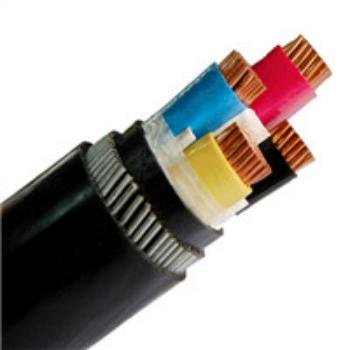
Steel wire armor (SWA) — typically 0.8–2.5 mm diameter galvanized steel wires, depending on cable OD and burial depth — is the standard for direct-buried industrial feeders, underground mine runs, and any environment where rodent damage or mechanical impact is a real operational risk. For weight-sensitive offshore or aerial applications, aluminum wire armor (AWA) cuts the mass noticeably. Neither appears in residential construction under normal circumstances; a home builder who specifies SWA on a branch circuit has either misread the spec or is dramatically over-engineering.
EMI shielding is the other layer that residential wiring never needs but industrial control and signal cables almost always do. A variable-frequency drive running a 200 kW motor generates significant conducted and radiated noise. Without a copper tape or braid shield on the drive cable, that noise rides back onto the plant’s instrumentation network and causes nuisance trips, corrupted sensor readings, or — in the worst cases — failed batch runs that nobody can diagnose for weeks because the root cause looks like a PLC logic error. The shield, bonded correctly at both ends (or one end only for certain signal cable types — this trips up installers regularly), is not optional.
How Compound Validation Connects to Real Project Risk
Specifying a cable material is only half the problem. Knowing whether that material will actually hold up in your specific environment over a 20–30 year cable life is a different question, and it’s where many procurement decisions go wrong. Jinda’s R&D process involves compound-level testing — oil immersion per IEC 60811, UV aging, cold-bend testing at rated minimum temperatures, and flame propagation trials — before any formulation moves into series production. For petrochemical plant cables, where hydrocarbon resistance isn’t a single test condition but a spectrum of different process fluids, validating against the actual chemicals present on-site changes the compound selection entirely. Mining cables face a different combined stress: methane atmosphere compliance (IECEx or ATEX certification), continuous flexing in draglines and continuous miners, and coal dust accumulation that can hold moisture against the jacket for months. A compound that passes flame testing in isolation can still fail the full combined-stress qualification.
ATEX and IECEx certifications require cable constructions to be tested and certified for use in explosive atmospheres; standard industrial cables without this certification cannot legally be installed in classified hazardous zones in most jurisdictions.True
Both the European ATEX directive (2014/34/EU) and the IECEx scheme impose specific requirements on equipment including cables used in explosive atmospheres; uncertified cables in Zone 1/Zone 2 or Division 1/Division 2 areas represent a compliance and safety violation.
The practical takeaway: if you’re procuring cable for anything beyond a standard dry-indoor industrial environment, the jacket and insulation specification deserves as much engineering attention as the conductor sizing. Getting the voltage and ampacity right while under-specifying the compound is how plants end up replacing cables at year four of a twenty-year asset life.
Installation Methods, Conduit Systems, and Cable Management Infrastructure
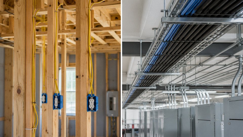
Walk through a typical house rough-in and you’ll see 14 AWG or 12 AWG NM-B cable — Romex, in most electricians’ parlance — stapled along stud faces, notched through plates, and landed on a single 200 A panel. The whole dwelling might consume 300 to 600 meters of cable, give or take, depending on square footage and how many circuits the designer bothered to split out. Runs are short. Bends are casual. A skilled residential crew can rough-in a 2,000 sq ft house in a day or two.
A mid-size manufacturing plant is a different discipline entirely.
The Infrastructure Layer Industrial Wiring Actually Requires
A plant producing, say, stamped metal components or processed food might route 30 to 80 kilometers of cable once you count every voltage tier — lighting feeders, 480 V motor branch circuits, 24 VDC control wiring, instrumentation cables, and medium-voltage distribution to transformer bays. That range depends heavily on plant footprint, process density, and how aggressively the design team consolidated routing paths. Every meter of that cable lives inside a containment system: rigid metal conduit (RMC) in areas with physical abuse risk, intermediate metal conduit (IMC) where weight savings matter and protection requirements still demand steel, cable trays in overhead runs where you need future access for additions, and wireways in panel rooms and marshalling areas. Direct burial and underground duct banks handle site distribution between buildings — polyvinyl chloride Schedule 40 or 80 duct encased in concrete is common, though some plants use HDPE for corrosive soil environments.
Residential NM-B isn’t listed for any of those applications. It’s not rated for conduit fill in most jurisdictions, it has no armor, and its jacket won’t hold up in a wet process bay for six months.
Conduit Fill, Tray Loading, and Bending Radius — the Engineering You Can’t Skip
Conduit fill calculations scale fast in industrial work. NEC Chapter 9 limits total cable cross-section to roughly 40% of conduit interior area for three or more conductors, which sounds simple until you’re pulling four 4/0 AWG conductors plus a ground through a 2-inch RMC run that someone decided to route around a structural column with three 90-degree bends. Each bend adds pulling tension — Southwire’s sidewall pressure formula and similar tools are standard in any serious plant electrical design. Get it wrong and you either can’t pull the cable at all or you damage insulation trying.
Cable tray has its own discipline. Steel ladder tray rated at 75 kg/m sounds generous until you stack 600 V power cables, instrumentation cables, and fiber alongside each other on a 15-meter overhead run. Tray loading calculations need to account for cable weight per meter (a 95 mm² copper power cable runs roughly 1.1 to 1.4 kg/m depending on construction), plus any accumulation of dust or process residue in dirty environments — something maintenance teams often forget until a tray support bracket fails.
Minimum bending radius is non-negotiable for larger cables. A 185 mm² armored cable may require a bending radius of 12 to 15 times the cable’s overall diameter. Violating that during a pull or at a termination point causes insulation stress and, eventually, premature failure — often at the worst possible moment.
Hazardous Locations and Hostile Process Environments
Industrial installations regularly encounter conditions that residential wiring codes simply don’t address. NEC Article 500 classifies hazardous locations by class (I for flammable gases/vapors, II for combustible dust, III for ignitable fibers) and division. IEC uses the Zone system — Zone 0/1/2 for gases, Zone 20/21/22 for dust. Either way, the cable selection, conduit sealing, and termination methods are mandated specifically, and an inspector will reject non-compliant work without discussion.
High-temperature zones near industrial ovens, kilns, or furnaces require cables rated for continuous operation at 90°C, 105°C, or in some cases 150°C or higher — standard THHN or XHHW won’t survive. Wet and corrosive process areas, common in food processing, chemical plants, and metal finishing, demand jacket compounds resistant to oils, acids, or cleaning agents. This is where specifying the right cable construction upfront saves a plant from rewiring corroded runs three years into operation.
Standard residential NM-B cable can be used in conduit in commercial or industrial settings as a cost-saving measureFalse
NM-B cable is generally not listed or permitted for use in conduit, raceways, or wet/damp locations under NEC 334.12. Using it in industrial conduit systems violates code and creates genuine failure risk.
Logistics: Drum Weights, Reel Handling, and Pull Station Planning
Here’s something procurement managers underestimate until the first delivery lands on site: large industrial cables don’t come in cardboard boxes. A 630 mm² copper cable on a steel reel can weigh 2 to 5 tonnes depending on drum length, which might be 200 to 500 meters per reel depending on the order specification and what the manufacturer can wind without exceeding transport limits. Jinda ships cables on heavy steel reels internationally — those reels need forklift handling at the port, at the warehouse, and at each cable pull station on site. A plant contractor who hasn’t pre-planned reel staging areas and pull point locations will lose days, sometimes weeks, maneuvering multi-tonne reels through a facility that’s already partially constructed.
Pull station spacing depends on conduit run geometry and calculated pulling tension limits — every bend and every meter adds to the load. In practice, experienced industrial electricians walk the route before ordering and specify drum lengths to match realistic pull segments, rather than ordering the maximum reel length and hoping it works out.
Residential work has none of this complexity. A 250-foot spool of 12 AWG NM-B weighs under 10 kg and fits in a tool bag. The operational gap between the two installation environments is that stark.
Grounding, Bonding, and Fault-Protection Architecture in Industrial vs. Residential Systems
Residential grounding is, by design, straightforward. A typical NM-B cable run pulls an equipment grounding conductor (EGC) — usually bare copper — alongside the hot and neutral conductors, all the way back to the main panel where it connects to a grounding electrode system: a ground rod, the metal water pipe, or both. GFCI receptacles or breakers cover wet locations like kitchens and bathrooms. The whole topology is intentionally simple because the hazards are manageable, the fault currents are relatively low, and most installations are done by a single electrician without a protection coordination study in sight.
Industrial grounding is a different discipline.
In a manufacturing plant or process facility, grounding stops being a single-path, panel-to-electrode arrangement and becomes a system — sometimes a literal buried copper grid under a substation or switchgear room. Multi-point equipment grounding means every motor frame, every control enclosure, every cable tray section, and every structural steel member gets bonded. This is not paranoia; it reflects the reality that fault currents in industrial feeders can reach tens of kiloamps, and without a low-impedance return path at every point, you get dangerous touch voltages appearing on equipment housings that a worker might grab.
The bonding conductor cross-sections alone illustrate the scale difference. A bonding jumper for a 4,000 A industrial feeder might be 120 mm² or larger. The entire branch circuit wiring in an average house rarely totals that much copper. For sensitive process equipment — variable frequency drives, PLCs, analytical instruments — isolated ground (IG) systems are common, running a dedicated insulated EGC back to a separate ground bus to avoid noise coupling from shared grounding paths. It adds cost and conduit fill, but the alternative is unexplained instrument drift or nuisance drive faults that waste days of troubleshooting.
Earthing System Selection Under IEC 60364
Engineers working on international projects have to specify the earthing arrangement explicitly. The IEC 60364 framework defines TN-S (separate neutral and protective earth conductors throughout), TN-C-S (combined PEN conductor up to a point, then split), TT (independent earth electrode at the installation, no connection back to the supply transformer earth), and IT (supply isolated from earth, with the installation equipment grounded through impedance or not at all).
Residential installations in most of Europe default to TN-C-S or TT without the designer making a conscious choice — the utility’s distribution network dictates it. Industrial engineers don’t have that luxury. An IT system, for instance, allows the plant to keep running on a first ground fault because no fault current path is completed until a second fault occurs. That’s genuinely valuable in continuous-process industries where an unplanned shutdown costs more per hour than most residential electrical installations cost in total. The tradeoff is that you need insulation monitoring devices (IMDs) watching the system constantly, and your maintenance team has to respond quickly when the IMD alarms — because the second fault is when you have a serious problem.
IT (ungrounded) systems allow continued operation after a single ground fault, provided insulation monitoring is in place and the first fault is located and cleared promptly.True
This is a documented characteristic of IT earthing systems under IEC 60364-1 and is widely applied in hospital operating theaters, offshore platforms, and continuous-process industrial facilities. The system does not complete a fault current loop on the first fault, but a second fault on a different phase creates a phase-to-phase fault condition that is dangerous and must be prevented by rapid response to IMD alarms.
Arc Flash Hazard Analysis: An Industrial-Only Discipline
Residential panelboards rarely generate dangerous arc flash energy. A 200 A, 240 V residential main panel might produce an incident energy level that poses minimal PPE requirements at normal working distance — the available fault current is simply too low to sustain a prolonged arc. Industrial switchgear at 480 V or 4,160 V is a fundamentally different situation.
NFPA 70E and IEC 62271 require facilities to perform arc flash hazard analysis — calculating available fault current, modeling bus clearing times, and establishing arc flash boundaries and required PPE for every piece of equipment someone might work on while energized. The results drive specification decisions: faster-acting fuses or current-limiting breakers reduce incident energy, sometimes dramatically. Bus clearing time matters enormously here. A relay that takes 0.5 seconds to clear a fault versus 0.05 seconds can push incident energy from a manageable 4–8 cal/cm² into a range requiring a full arc flash suit and potentially making the task impractical to perform while energized at all.
Ground fault protection relays on industrial feeders — required by NEC 230.95 on solidly grounded systems 150 V to ground and above 1,000 A — provide a layer of protection that simply has no residential equivalent. They trip on low-level ground faults too small to operate an overcurrent device but large enough to start a fire or cause equipment damage over time.
Getting these systems specified correctly, coordinated with the upstream protective devices, and properly documented is the work of a protection engineer, not an electrician running cable. That’s the real gap.
Applicable Standards, Certifications, and International Compliance Obligations
Regulatory frameworks for wiring don’t exist in a vacuum — they evolved in response to real accidents, real fires, and real electrocutions, which is why the gap between residential and industrial compliance requirements is so wide. A procurement manager sourcing cable for a petrochemical plant in Southeast Asia faces an entirely different compliance matrix than someone outfitting a housing development in Ohio. Getting that matrix wrong costs money at best, and lives at worst.
Residential Standards: Harmonized for Predictable Environments
North American residential wiring sits primarily under NEC Articles 100 through 230, which cover definitions, wiring methods, services, feeders, and branch circuits in dwelling units. These articles assume relatively stable loads, trained but not necessarily specialist installers, and environments without chemical exposure or continuous industrial duty. In IEC-governed regions — most of Europe, large parts of Asia and Africa — IEC 60364-7 special locations subdivisions (701 through 708) handle bathrooms, swimming pools, marinas, and similar dwelling-adjacent environments, building on the base installation rules in 60364-4 and 60364-5. The UK follows BS 7671 (the IET Wiring Regulations, currently 18th Edition), which is closely aligned with IEC 60364 but maintains some distinctly British deviations in terminology and protective conductor sizing. Australia and New Zealand work under AS/NZS 3000, the “Wiring Rules,” which is similarly IEC-harmonized but reflects local distribution practices like TN-C-S earthing arrangements common in those grids.
The common thread across all of them: these standards assume predictable, bounded hazard environments. Residential wiring is not simple — anyone who has pulled permits on a large custom home knows the detail involved — but the hazard profile is comparatively narrow.
Industrial Standards: A Much Larger, More Fragmented Landscape
Industrial installations layer on substantially more complexity. In North America, NEC Articles 430 and 440 govern motor circuits and air-conditioning equipment respectively, each with their own overcurrent protection sizing logic that differs meaningfully from simple branch circuit rules. Articles 500 through 516 cover classified hazardous locations — Class I, II, and III; Divisions 1 and 2 — and the Zone system introduced in Article 505. Article 670 addresses industrial machinery, and Article 680 handles pools and fountains in commercial or public contexts. These are not interchangeable; wiring a Class I Division 1 area with cable rated only for dry, non-hazardous locations is a code violation that can also trigger an explosion.
In IEC jurisdictions, IEC 60364-4-41 (protection against electric shock) and 60364-5-52 (cable selection and installation) form the backbone, while the IEC 60079 series — currently running to more than 20 parts — governs equipment and wiring in explosive atmospheres in considerable detail. IEC 60364-7-710 covers medical locations, which have their own fault-tolerance and isolation requirements that are frankly more demanding than most general industrial applications. For power system engineers designing plant distribution above the branch circuit level, IEEE 141 (the “Red Book”) remains the practical reference for industrial power distribution architecture, covering short-circuit calculations, coordination, and transformer sizing in a way that no single NEC article does.

Cable Product Certifications: What Buyers Should Actually Verify
The standards above govern installation. Separately, cable products themselves carry certifications that confirm the conductor, insulation, and jacket construction meet minimum tested performance levels. In North America, UL 44 covers thermoset-insulated wire (think XHHW-2), UL 83 covers thermoplastic-insulated wire (THHN/THWN), and UL 1277 covers electrical power and control tray cables — the type you’ll see in cable tray throughout a food processing or petrochemical plant. These are not interchangeable listings; a cable with only UL 1277 listing is not automatically acceptable as a substitute for UL 44 in a raceway application, even if the voltage rating looks the same.
Under the IEC framework, IEC 60227 covers PVC-insulated cables for fixed wiring, IEC 60228 defines conductor classes (Class 1 through Class 6, which matters enormously for flexibility and termination compatibility), and IEC 60502 governs power cables from 1 kV through 30 kV — the workhorse standard for most LV and MV industrial cable procurement outside North America. For medium-voltage applications above 30 kV, IEC 60840 takes over. Where smoke and halogen toxicity matter — enclosed spaces like offshore platforms, tunnels, and data centers — LSZH (low-smoke zero-halogen) performance is validated under IEC 60332 for flame propagation and IEC 61034 for smoke density. Both tests are required; passing one doesn’t imply the other.
A product datasheet alone is sufficient proof of IEC or UL compliance when sourcing industrial cable.False
Datasheets are marketing documents with no third-party verification. Compliance must be confirmed through certified test reports issued by accredited labs (SGS, TÜV, Bureau Veritas, or equivalent), traceable to specific production batches. Reputable manufacturers maintain these on file and provide them on request.
Export Compliance and Multi-Standard Products
Projects with international supply chains often need cable that satisfies more than one regulatory regime simultaneously — an LNG terminal project might require IEC 60502 compliance for the European operator’s specifications, GB/T 12706 (the Chinese national equivalent) for factory acceptance testing, and specific LSZH performance per IEC 60332-3 for the module builder’s fire safety requirements. Jinda designs cables to meet simultaneous compliance with IEC, GB, and selected UL or BS standards, which allows a single cable type to ship into projects across multiple jurisdictions without costly requalification at each destination. That matters most on large EPC contracts where the cable schedule might list fifty to eighty line items and the project can’t absorb six-month approval cycles for each one.
Third-party testing through SGS, TÜV Rheinland, Bureau Veritas, or equivalent accredited bodies is what actually validates compliance claims. Factory audits add another layer — they confirm that the production process capable of generating the certified product is still in place, not just that a prototype passed a test three years ago. When you’re sourcing industrial cable for a long-term project, request the certified test reports with lab accreditation details, the relevant cable construction drawing, and — if volumes justify it — a witnessed factory audit. A datasheet is a starting point, not evidence.
Lifecycle Cost, Maintenance Intervals, and Total Cost of Ownership Compared
Residential cable is, in a sense, a set-and-forget product. NM-B or THHN run through a house wall in 1995 is almost certainly still there, still functional, and nobody has thought about it once. Normal service life runs 30–50 years, and replacement is almost always driven by a kitchen remodel or a panel upgrade — not by the cable itself failing. Maintenance intervals are effectively zero. That’s not a criticism; it’s exactly what the application requires.
Industrial wiring doesn’t get that luxury.
Lifespan in an industrial context is a range that depends heavily on what the cable is doing. Fixed power distribution feeders in a dry switchroom can realistically reach 25–40 years with proper termination maintenance and no thermal abuse. Continuous-flex cables on robotic arms or cable tracks are a different story — 10–20 million flex cycles sounds like a lot until you calculate how fast a 60-cycle-per-minute press chews through that budget, and in practice you might be pulling and replacing a flex cable every 3–5 years. In aggressive environments — chlorinated wash-down areas, petrochemical atmospheres, high-UV outdoor runs — even a well-specified cable may degrade faster than the nameplate rating suggests if the jacket compound wasn’t matched carefully to the actual chemistry involved.
The Real Cost Equation Is Almost Never About the Cable
The cable itself is rarely the expensive part of an industrial failure. A reel of 35 mm² VFD cable might run $4–$12 per meter depending on shielding and jacket spec, which feels significant on a purchase order. What procurement managers sometimes underweight is that a single unplanned cable failure in a continuous-process line — automotive stamping, food packaging, semiconductor fab — can generate downtime costs ranging from roughly $10,000 to $500,000 per hour depending on the industry and line configuration. The exact number depends on line throughput value, whether parallel capacity exists, and how long diagnostics take before the repair even starts.
Specifying a higher-grade industrial cable at the design stage is almost always cheaper than emergency replacement after an unplanned failure.True
The differential cost between a standard and premium cable specification is typically a small fraction of even one hour of production downtime in most industrial environments; engineering studies and maintenance records from continuous-process industries consistently support this conclusion.
That’s the argument for spending the extra money upfront. It’s not abstract.
Predictive Maintenance Tools That Don’t Exist in Residential Practice
Facilities engineers running industrial installations have a toolkit for catching cable degradation before it becomes a failure event. Partial discharge testing identifies voids or delamination in medium-voltage insulation while the cable is still in service. Insulation resistance (IR) trending — not a single snapshot, but a log of readings over months or years — catches moisture ingress or thermal damage as a trend rather than a sudden surprise. Thermographic surveys with an infrared camera during loaded operation find hot terminations and overloaded conductors that the protection scheme won’t catch until it’s too late. Time-domain reflectometry (TDR) can locate a developing fault or a physical damage point to within a meter or two without pulling the cable.
None of these techniques are relevant to a residential circuit. You wouldn’t IR-trend the wiring in a bedroom. But in a plant running three shifts, a quarterly IR log on your main feeder cables is cheap insurance.
Supply Continuity as a TCO Factor
One aspect of total cost of ownership that rarely shows up in a cable spec sheet is supply geometry consistency — the guarantee that a spare reel purchased today will actually match what’s installed in the tray. Industrial plants routinely carry strategic cable inventory for critical circuits, and if a manufacturer quietly changes conductor stranding count, jacket diameter, or insulation wall thickness between production runs, that spare reel may not terminate cleanly or pull through the same conduit without rework.
Jinda’s approach to long-term supply partnerships specifically addresses this: fixed cable geometry and construction documentation is maintained across multi-year contracts, so the cable you specify today and the cable you order as a replacement five years from now are dimensionally and electrically equivalent. For a plant with hundreds of motor feed circuits, that consistency isn’t a minor convenience — it’s a genuine maintenance cost driver.
Frequently Asked Questions About Residential and Industrial Wiring Differences
Can residential cable be used temporarily in an industrial setting?
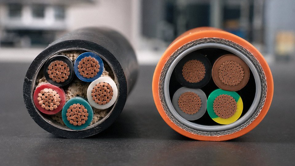
No — and “temporarily” is exactly the word that gets people hurt or fined. A standard residential NM-B or flat TPS cable carries a voltage rating of 300 V or 600 V, insulation rated for 60°C or 75°C, and no mechanical protection whatsoever against abrasion, oil, or chemical splash. Put that cable on a 480 V three-phase circuit and you’ve already violated the voltage rating. Run it across a factory floor where a forklift might cross it, and you have a crush hazard. Even a brief duration — say, a contractor bridging a motor circuit during commissioning — violates NEC 110.3(B) and IEC installation rules, exposes the site to liability, and can invalidate insurance coverage the moment an incident occurs. There is no code-compliant “temporary” exception for using residential cable in an industrial environment. Use the right cable from day one.
What wire gauge is standard for industrial three-phase motor circuits?
It depends, and anyone who gives you a single number without asking about voltage, horsepower, distance, and ambient temperature is guessing. As a working example: a 22 kW motor running at 480 V draws roughly 30–33 A at full load. Under NEC 430 continuous-duty rules, you size the conductor at 125% of that, which puts you at around 40 A minimum ampacity — typically 8 AWG copper at minimum, though 6 AWG (10 mm²) is more common once you apply conduit fill and ambient derating. That’s already three to four wire sizes heavier than a 20 A residential branch circuit. For a 75 kW motor, or a long run with significant voltage-drop concern, you may be pulling 35 mm² or larger. Always run the full derating calculation; motor circuits in enclosed conduit in a hot machine room can derate significantly from the published ampacity table.
Is XLPE insulation always better than PVC for industrial use?
Not always. XLPE’s higher temperature ceiling (usually 90°C continuous, 250°C short-circuit) and superior dielectric strength make it the right choice for high-load, high-voltage applications. But PVC has real advantages in certain scenarios — it’s inherently more resistant to some mechanical damage, and in applications where the primary concern is limiting flame spread in a congested cable tray, a well-specified PVC compound may actually outperform a standard XLPE jacket. Where toxic fume generation during fire is the overriding concern — tunnels, underground transit, densely occupied facilities — neither standard PVC nor standard XLPE is the answer; you want LSZH (low smoke zero halogen) construction. The honest answer is that insulation selection should follow a hazard profile review, not a default preference.
How do I verify that an imported industrial cable actually meets the claimed IEC standard?
Request the full third-party type-test report, not a summary certificate. Check that the testing laboratory holds current accreditation under ILAC or a recognized national body. Then compare the tested cable construction — conductor cross-section, insulation thickness, jacket material, screen design if applicable — against the drum markings on the cable you actually receive. Discrepancies between the tested construction and the delivered product are where compliance failures hide.
Jinda provides complete third-party type-test documentation, drum-marking traceability, and export compliance packages for industrial cable projects.True
Documented practice for export-oriented manufacturers supplying IEC-regulated markets; Jinda's project support process includes full technical documentation for customs, engineering review, and site acceptance testing.
What is the minimum short-circuit withstand requirement for industrial cables?
The adiabatic equation in IEC 60949 (and referenced in IEC 60228 conductor tables) gives you the framework: withstand current scales with conductor cross-section and the square root of fault duration. For a 35 mm² copper conductor, a 1-second fault withstand typically falls in the range of 3.3–3.6 kA, depending on the initial conductor temperature and the conductor’s k-factor. That’s a meaningful number for industrial protection coordination. A residential 12 AWG (2.5 mm²) conductor? Its 1-second withstand is roughly 230–250 A — adequate for a 20 A breaker, irrelevant to industrial bus protection design. These figures matter when you’re selecting cables for switchgear feeder applications where the available fault current from the utility or transformer is several kiloamperes.
Do industrial cables need to be shielded?
Not universally, but the cases where shielding is necessary come up constantly in modern plants. VFD output cables are the biggest one — the steep voltage rise times generated by variable-frequency drives create high-frequency leakage currents that travel back through the cable jacket if there’s no continuous shield bonded at both ends, causing interference with nearby instrumentation and, in some configurations, creating a genuine touch-voltage hazard on cable surfaces. Instrumentation and signal cables in high-EMI environments — near large motors, welding equipment, induction heaters — need shielded construction to maintain signal integrity. Power cables in standard distribution applications generally do not require shielding. The decision comes down to what’s on the circuit and what’s nearby.
Why does Jinda offer cables in both IEC and North American configurations?
Because real industrial projects are messy. An oil refinery expansion, a large data center, a port terminal — these facilities frequently have equipment from multiple countries of origin, with engineering specifications that mix IEC and NEC/CSA requirements across a single site. A compressor skid built in Europe arrives with IEC-rated interconnects; the local distribution board is designed to NEC. If you’re sourcing cable from multiple suppliers to cover both standards, you multiply your qualification work, your documentation packages, and your risk of a specification mismatch slipping through. A single-source supplier that manufactures to both frameworks reduces that friction — and when something needs to be traced or re-certified, you’re dealing with one technical contact instead of three.