Spec sheets never explain why a “cable” is a cable, and that gap quietly causes real problems on the plant floor — procurement teams conflate cables with cords, wires, and conductors, orders come back wrong, and you lose days waiting on a re-quote. In high-voltage or marine projects especially, where a mistaken substitution can mean a ground fault or a failed type test, the vocabulary matters as much as the datasheet.
The word “cable” traces to Old North French cable and Late Latin capulum, meaning a rope or halter. It entered English maritime use around the 13th century, naming the heavy anchor rope on a tall ship — roughly 100 fathoms (about 185 m) long. That physical, load-bearing meaning of twisted or laid strands working together under tension carried straight into modern electrical engineering, where a cable still means multiple conductors stranded, insulated, and bound into a single, mechanically robust assembly.
What’s interesting is how little that original idea has actually changed — whether you’re talking about a hemp anchor cable on a square-rigger or a 750 kV HVDC submarine cable pushing power between continents, the defining characteristic is the same: strands, combined, to handle something no single element could manage alone. That etymology isn’t trivia. It’s a working definition that tells you exactly what a cable is supposed to do, and why calling a single insulated conductor a “cable” is technically wrong in ways that occasionally matter.

The Anatomy of a Cable Name: How Modern Standards Define What Qualifies as a Cable vs. a Wire vs. a Cord
Most procurement documents use “wire,” “cable,” and “cord” interchangeably. On the factory floor, that habit causes real problems — wrong product specified, wrong test applied, wrong approval stamp, shipment rejected at customs. Getting the terminology right is not pedantry; it’s the foundation of a defensible bill of materials.
Wire: The Building Block
A wire, in the strictest sense, is a single conductor — solid or stranded — that may be bare or carry only a thin functional coating such as tin, silver, or nickel. IEC 60050-461 treats it as the elemental unit from which cable assemblies are constructed. You’ll find bare copper wire wound into motor coils, thin-tinned wire soldered onto PCB terminals, and solid aluminum wire drawn into overhead transmission strands. What a wire is not is a finished, field-installable product. Without insulation rated to a system voltage and some form of mechanical protection, it’s a component, not an article.
Stranding matters here. IEC 60228 classifies conductors from Class 1 (solid) through Class 6 (highly flexible, fine-wire stranded). A Class 2 stranded conductor is still just a wire until someone extrudes insulation over it. The distinction sounds obvious until you’re trying to reconcile a Chinese manufacturer’s GB/T 3956 conductor class against an IEC 60228 Class 5 specification on a European project — they’re broadly aligned but not always identical in allowable resistance per meter.
Cable: The Defined Assembly
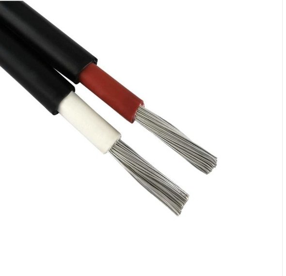
Per IEC 60050-461, a cable is one or more insulated conductors, with or without a collective sheath, designed for the transmission of electrical energy or signals. The critical qualifier is insulation. The moment you extrude XLPE, PVC, or EPR over that conductor and add an outer jacket — or even just a bedding layer — you have crossed from wire into cable territory.
In practice, most cables add more: a filler to maintain a round cross-section, a binder tape, an armoring layer (steel wire armour or aluminium wire armour for direct-burial or mechanical protection), and a sheath. High-voltage cables above roughly 6 kV typically include a conductor screen and an insulation screen to manage field distribution. A 110 kV XLPE cable and a 1.5 mm² twin-and-earth domestic cable are both “cables” by this definition — they differ by about four orders of magnitude in conductor cross-section and roughly the same in cost per meter.
IEC 60050-461 defines a cable as one or more insulated conductors with or without a collective sheath, distinguishing it from bare wire by the mandatory presence of conductor insulation.True
IEC 60050-461 (the International Electrotechnical Vocabulary for cables) specifies insulation as the defining structural feature separating a cable from a bare wire or conductor.
Cord: Flexibility as a Design Requirement
A cord is a specific subtype of cable assembly — flexible, intended for repeated movement, and almost always connecting portable or semi-portable equipment to a supply point. IEC 60245 and IEC 60227 cover rubber and PVC flexible cords respectively. Conductor stranding is Class 5 or Class 6 by default. Voltage ratings are typically 300/300 V or 300/500 V, occasionally 450/750 V. You wouldn’t specify a cord for a fixed installation inside cable tray, and you definitely wouldn’t run a rigid thermoplastic-sheathed cable to a handheld power tool and expect it to survive a thousand flex cycles.
NEC Terminology: A North American Divergence
The NEC (NFPA 70) uses its own vocabulary that doesn’t map cleanly onto IEC. It distinguishes “cable assemblies” (NM-B, MC, AC, USE-2 — each a defined product type with its own article in the code) from individual “conductors” and “cords.” An international buyer sourcing cable for a US project needs to specify the NEC cable type explicitly, not just the IEC voltage designation. A cable meeting IEC 60502-1 for 0.6/1 kV does not automatically satisfy Article 330 (MC Cable) requirements. This is a routine source of friction on cross-border EPC projects.
Chinese GB Standards: Reading the Alphanumeric Code
Manufacturers operating under Chinese national standards — including GB/T 2952 (cable outer sheaths) and GB/T 12706 (medium-voltage XLPE cables) — encode the entire product specification into a structured alphanumeric designation. Take “ZR-YJV22-8.7/15 kV 3×95”: “ZR” means flame-retardant, “YJ” means XLPE insulation, “V” means PVC sheath, “22” means double steel tape armour with PVC outer sheath, “8.7/15 kV” is the rated voltage (conductor-to-screen / conductor-to-conductor), and “3×95” is three conductors at 95 mm². Once you understand the encoding logic, you can read a Chinese cable spec sheet without a translator. Miss one character and you’ve ordered unarmoured cable for a direct-burial trench.
Wire vs. Cord vs. Cable: Side-by-Side
| Feature | Wire | Cord | Cable |
|---|---|---|---|
| Typical structure | Single conductor, bare or lightly coated | Multiple insulated conductors, flexible jacket | One or more insulated conductors, often with bedding, armour, sheath |
| Insulation layers | None or functional coating only | Conductor insulation + flexible outer sheath | Conductor insulation + optional screens + outer sheath |
| IEC 60228 flexibility class | Class 1–2 (solid/stranded) | Class 5–6 (flexible/highly flexible) | Class 1–5 depending on application |
| Typical voltage range | N/A (component) | 300/300 V to 450/750 V | 300/500 V up to 750 kV (HVDC) |
| Primary application | Component inside cables, coils, busbars | Portable equipment, appliances, extension leads | Fixed wiring, power distribution, signal transmission |
The table above is a working reference, not a legal definition — always defer to the applicable project standard. In practice, the boundary between a heavy flexible cord and a light flexible cable gets genuinely blurry around the 0.6/1 kV range, and different certifying bodies will draw the line in slightly different places. When in doubt, ask your supplier for the specific IEC or GB product standard the item was designed and tested to, not just the voltage rating.
The Transatlantic Telegraph Cable of 1858: The Engineering Project That Fixed the Word in the Global Vocabulary
Before 1858, “cable” still meant rope to most of the world. What happened that August changed the word permanently.
Cyrus Field, an American paper merchant with no formal engineering background, spent the better part of four years pushing a project that serious engineers repeatedly told him was impractical: lay roughly 3,200 km of signal-carrying cable across the North Atlantic seabed, from Valentia Island off the Irish coast to Trinity Bay, Newfoundland. The depth in places exceeded 3,000 meters. Nobody had reliable bathymetric charts. Nobody had built anything remotely like this cable before, and nobody was certain the signal could travel that distance without fading into noise.
What the Cable Was Actually Built From
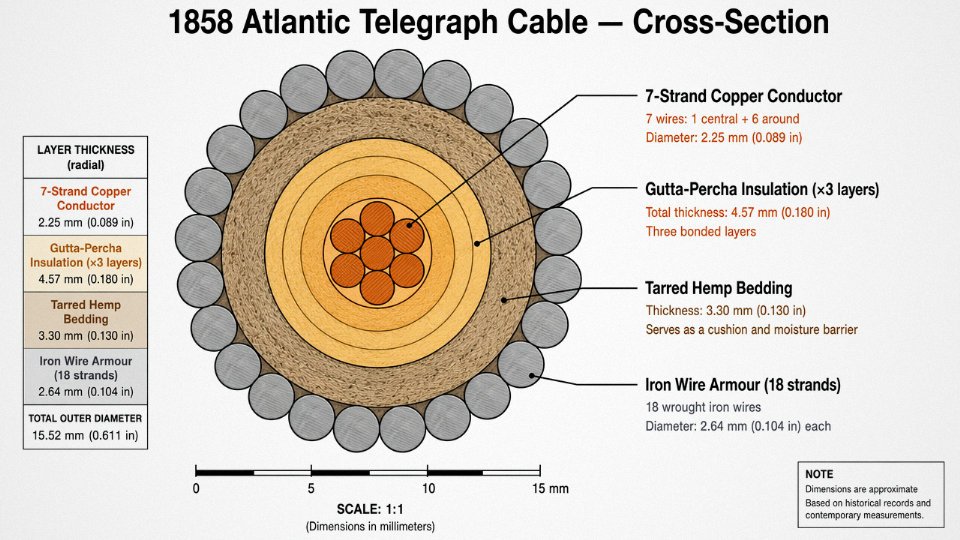
The construction logic is worth understanding in detail, because it maps almost perfectly onto what a modern armored submarine cable looks like in cross-section. The 1858 cable used a central conductor of seven twisted copper strands — already recognizing that a stranded conductor handles mechanical stress better than a solid one. Around that conductor went three layers of gutta-percha, a natural latex tapped from trees in Malaya that was, at the time, the only known material with adequate dielectric properties and enough flexibility to survive coiling in a ship’s hold. Over the gutta-percha went tarred hemp yarn as a bedding layer to cushion the armor and keep moisture from wicking inward. The outer armor consisted of eighteen stranded iron wires, helically applied.
That sequence — conductor, insulation, bedding, armor — is not a historical curiosity. It is the structural DNA of every armored submarine power cable and armored control cable manufactured today. The materials have changed dramatically (cross-linked polyethylene instead of gutta-percha, galvanized steel wire instead of plain iron), but the logic of each layer’s function has not moved.
The Failure, and Why It Matters
The 1858 cable worked. For 27 days. Queen Victoria sent a congratulatory message to President Buchanan; church bells rang in New York. Then the signal degraded and died. The cause was not the design itself but Wildman Whitehouse, the project’s chief electrician, who applied voltages far above the agreed operating limit in an attempt to push signal speed — up to 2,000 volts across insulation rated for a fraction of that. The gutta-percha broke down. The cable went silent on September 18, 1858.
The 1858 Atlantic Telegraph Cable failed because of design flaws in the gutta-percha insulationFalse
Post-failure analysis led by engineer William Thomson (later Lord Kelvin) attributed the failure primarily to Whitehouse's unauthorized over-voltage testing, not to an inherent insulation design flaw. The 1866 cable, using the same basic insulation approach but with proper operating discipline, worked continuously.
The 1866 attempt, using the purpose-built SS Great Eastern — the only ship large enough to carry the full cable length in one load — succeeded and remained in service for years. William Thomson’s mirror galvanometer allowed detection of the faint signals that Whitehouse’s brute-force approach had tried to overpower. The lesson, blunt and still relevant: insulation systems have voltage ratings for reasons, and exceeding them to recover performance is how you lose equipment.
How a Noun Became a Verb
Newspapers covering the 1858 project used “cable” incessantly, and not just as a noun. Within weeks, journalists and diplomats were writing about “cabling” messages across the Atlantic. By the 1860s and 1870s, sending an international telegram was simply “sending a cable.” Receiving one was “getting a cable.” The infrastructure had branded itself into the language so thoroughly that even after telegraphy disappeared, the word stayed — moving forward into electrical power distribution, telephony, and eventually fiber optics.
Today, over 400 active submarine cable systems carry somewhere above 95% of international internet traffic. Every one of them is still called a cable, and every one of them uses a recognizably similar layered cross-section to the thing Cyrus Field’s team lowered into the North Atlantic. The word followed the engineering logic because the engineering logic turned out to be durable.
For anyone manufacturing or specifying armored cables — whether a 35 kV submarine power feeder or a multicore instrumentation cable with steel wire armor — that lineage is not just history. The construction standards, the layer functions, the vocabulary on the datasheet: it all traces back to that cross-section developed under pressure in the 1850s and proven in the deep water of the Atlantic.
Conductor, Insulation, Screen, Armor, Sheath: Why Each Layer Earns Its Place in a Cable’s Cross-Section
A cable cross-section isn’t a design committee’s compromise. Every layer exists because removing it causes a specific failure mode — arc flash, insulation breakdown, ground fault, mechanical destruction, or a fire that travels 50 meters down a cable tray. Understanding what each layer actually does is the difference between specifying correctly and discovering the problem during commissioning.
The Conductor: Where Cross-Section in mm² Actually Comes From
Annealed copper to IEC 60228 is the baseline most engineers assume. Class 1 is solid, used in fixed installations where flexibility doesn’t matter and you want the lowest DC resistance per mm². Class 2 is stranded — still common in power cables. Classes 5 and 6 are fine-stranded, used in flexible trailing cables and portable equipment. The stranding geometry matters beyond just flexibility: tightly bunched round wires in a Class 2 conductor give a predictable fill factor and consistent AC resistance, whereas a rope-lay Class 6 conductor introduces more interstrand voids and slightly higher effective diameter for the same nominal cross-section.
Aluminum conductors complicate things. The conductivity is roughly 61% of copper’s, so a 150 mm² aluminum conductor approximates a 95 mm² copper conductor for current rating — roughly, because the actual derating depends on installation method, ambient temperature, and grouping per IEC 60364-5-52. Aluminum is cheaper per ampere than copper under most market conditions, but the termination practice is unforgiving: oxide layer formation, cold-flow creep at connections, and the need for proper compression lugs mean aluminum is a legitimate engineering choice, not a shortcut, only when the installation team knows what they’re doing.
Insulation: Voltage Class Drives Material Selection
XLPE dominates medium- and high-voltage work for good reason. Dielectric strength typically runs 20–30 kV/mm depending on formulation and test method, operating temperature ceiling is 90 °C continuous (250 °C short-circuit), and it handles moisture far better than PVC above 1 kV. PVC remains the workhorse for low-voltage cables — cost-effective, easy to process, but limited to 70 °C continuous and unsuitable for voltages above about 3.3 kV in practice. EPR (ethylene propylene rubber) is the choice for flexible MV cables, mining trailing cables, and applications with significant mechanical flexing — it tolerates movement that would crack XLPE over time. LSZH compounds give up some mechanical toughness compared to PVC but are mandatory in confined spaces with limited ventilation: tunnels, offshore platforms, public buildings, anywhere that halogen-generated HCl gas in a fire creates casualties beyond the fire itself.
Semiconducting Screens: The Layer That Prevents Field Concentration
At voltages above roughly 3.3–6 kV (depending on the standard and the cable construction), the electric field distribution around a stranded conductor is not uniform. Strand gaps create local field intensification that degrades insulation over months or years. The inner semiconducting layer, applied directly over the conductor, smooths those irregularities. The outer semiconducting layer, applied over the insulation surface, provides a well-defined equipotential boundary. IEC 60502-2 requires this construction for cables rated 6 kV and above; IEC 60840 extends similar requirements to 150 kV and beyond. Skipping or damaging either layer — even a nick during installation — creates a partial discharge site that will eventually fail. In practice, the outer semi-con is the layer most frequently damaged during pulling, which is why experienced jointers inspect it carefully before jointing.
Semiconducting screens in MV/HV cables are mandatory under IEC 60502-2 for voltages 6 kV and above to equalize electric field distribution and prevent insulation degradation.True
IEC 60502-2 explicitly requires conductor and insulation screens for cables rated from 6 kV upward; the physics of field concentration at conductor strand gaps makes this a structural necessity, not a preference.
Metallic Screen and Armor: Two Different Jobs, Often Confused
The copper tape or wire screen serves an electrical function: it provides a low-impedance fault current return path and electromagnetic shielding. For a screened MV cable, the screen carries earth fault current back to the source, so its cross-section must be sized for the prospective fault level and fault clearance time — undersized screens burn off during a fault before the protection operates.
Steel wire armor (SWA) and steel tape armor (STA) are mechanical protection, full stop. SWA handles direct burial, pulling tension, and rodent damage. STA provides crush resistance and suits cables in conduit. Aluminum wire armor (AWA) is used on single-core cables where steel armor would introduce unacceptable eddy current losses from the magnetic field of a single-phase conductor — an AWA cable on a 33 kV single-core circuit runs noticeably cooler than the equivalent SWA, and over a long run the energy difference is not trivial.
Outer Sheath: The Layer Everyone Touches but Rarely Specifies Carefully
PVC sheaths to IEC 60811 ST1 or ST2 grades cover the majority of installations. ST2 is the enhanced compound with better low-temperature flexibility. Polyethylene (PE) gives better water resistance and lower dielectric loss for buried cables. Polyurethane (PUR) handles abrasion in drag-chain and machine-tool applications far better than either. LSZH jackets under EN 50575 (CPR) now carry a fire performance classification — Eca through Aca — which affects specification in European construction projects and is increasingly referenced in Middle East and Asian projects that mirror EU standards.
Sheath color and marking under IEC 60332 aren’t decorative. Black PE typically signals a UV-stabilized outdoor or buried cable; orange warns of buried HV presence; the CPR marking must appear at specified intervals. Getting the sheath wrong doesn’t usually cause immediate failure, but it causes problems during inspections, warranty disputes, and — in fire scenarios — real consequences.
Reading the Layers Together: A 3-Core 95 mm² 11 kV XLPE SWA Cable
A typical cable of this specification builds up roughly like this: the 95 mm² stranded copper conductor (Class 2, approximately 11–12 mm diameter across the bundle), then an extruded inner semiconducting layer of 0.5–1 mm, then XLPE insulation of approximately 3.4 mm radial thickness to meet the 12/20 kV voltage rating, then the outer semiconducting layer at 0.5–1 mm, then copper tape screen, then a bedding layer, then a layer of galvanized steel wires (SWA, typically 4–5 mm wire diameter arranged helically), then the final PVC or LSZH outer sheath. Overall diameter typically lands in the 60–70 mm range depending on the manufacturer’s lay-up. That outer diameter directly determines the minimum installation bend radius — commonly stated as 12× to 15× cable diameter for armored cables, though the actual limit depends on conductor stranding class and whether the bend is made during installation or in service. Undershooting the bend radius on an 11 kV XLPE cable is one of those errors that doesn’t show up immediately; it shows up as a partial discharge fault two or three years later.
Voltage Classes and Cable Families: Matching the Right Product to LV, MV, HV, and Specialty Applications
The cable market spans an almost absurd range — from 0.05 mm magnet wire to 750 kV HVDC submarine links. Procurement engineers who treat all of it as “cable” end up specifying the wrong product, which in practice means re-ordering under time pressure, absorbing derating penalties, or worse, a fault that shuts down a substation bay. A working map of voltage classes and application families prevents most of those mistakes before they start.

Low-Voltage Cables (Up to 1 kV)
This is by volume the largest segment, covering everything from building distribution to motor feeds to instrumentation loops. Common European-designation products — NYY, NYMHY, H07V-R — sit here, all governed by IEC 60502-1 for power cables and supplementary standards for control and instrumentation types. Insulation wall thickness for LV cores typically runs 0.7–1.0 mm, depending on conductor cross-section and temperature rating; that range matters when you’re stuffing cables through conduit or calculating bend radius in a cable tray.
PVC remains the workhorse insulation at this level. LSZH (halogen-free, low-smoke) has been eating into PVC’s share steadily, particularly in tunnels, rail stations, and data centers where toxic fume generation during fire is a regulated concern. In most industrial plants I’ve seen, the switch to LSZH happens floor by floor rather than all at once — a pragmatic, if slightly messy, reality of capex constraints.
Medium-Voltage Cables (1–36 kV)
Step up to MV and the construction requirements change fundamentally. IEC 60502-2 mandates conductor screens and insulation screens — the semiconducting layers that grade the electric field and prevent partial discharge at the insulation surface. Skip or underspecify those screens and you’re looking at premature insulation failure, typically showing up two to five years in rather than at commissioning. Industrial plant feeders, wind farm collection circuits (the 33 kV ring main connecting turbines to the substation), and urban underground distribution are the dominant applications here.
Jinda’s MV production covers 6 kV through 35 kV across this class. Typical XLPE insulation thickness in this range runs from roughly 3.4 mm at 6/10 kV up to around 8–9 mm at 26/35 kV, though exact wall depends on conductor size and installation method. Lead times for bulk MV orders vary considerably — straightforward 10 kV XLPE in standard cross-sections might ship in three to five weeks from a stocked facility, while 35 kV armored with non-standard conductor sizing can run eight to twelve weeks.
High-Voltage Cables (36–220 kV)
Above 36 kV, you’re in IEC 60840 territory. XLPE has effectively displaced paper-oil (PILC) designs above 66 kV — the combination of dry design simplicity, lower dielectric losses, and handling convenience is decisive. What catches project teams off guard at HV is not the cable itself but the jointing and termination systems. A 132 kV cable joint is a precision field operation; installation workmanship accounts for a disproportionate share of early failures in underground HV circuits. Specify the joint system at the same time as the cable, not as an afterthought.
XLPE insulation is standard practice for high-voltage cables above 66 kV in new installationsTrue
Mass-impregnated paper and oil-filled cable designs still exist in legacy networks, but virtually all new HV cable projects above 66 kV specify extruded XLPE per IEC 60840 due to lower losses, no oil containment requirement, and easier jointing.
Extra-High-Voltage and HVDC Cables (Above 220 kV)
HVDC cable engineering operates under IEC 62895 for land cables and IEC 63026 for submarine. The fundamental split is between mass-impregnated non-draining (MIND) cables — a mature technology used in some subsea links for decades — and extruded XLPE DC cables, which have matured enough since the early 2000s to dominate new offshore wind grid connections. Space charge accumulation under DC stress is the insulation physics issue that separates AC-capable XLPE from properly qualified DC-rated XLPE; they are not interchangeable, and procurement documents that specify “XLPE HV cable” without clarifying AC or DC have caused real project delays.
Specialty Cable Families
A handful of application-specific families warrant their own specs regardless of voltage class. Fire-resistant cables qualified to IEC 60331 or BS 6387 category CWZ must maintain circuit integrity during a fire — used in emergency lighting, fire alarm, and safety system wiring where the cable has to keep working while the building is burning. HFFR/LSZH cables to IEC 60332-3 address flame spread and smoke density without necessarily being fire-resistant; the two properties are often confused and should not be treated as equivalent.
Mining cables carry mechanical robustness and flexibility requirements far beyond standard power cable specs. Railway signaling cables have to meet EMC and cross-talk limits that are irrelevant to power distribution. Solar PV DC cables — IEC 62930 / EN 50618 — are rated for UV exposure, dual-insulation voltage, and the polarity reversal stress profile that a standard building wire was never designed for. Using standard NYY on a PV string because it was cheaper is a failure mode that shows up as insulation tracking damage within a few years in high-irradiance climates.
Product Selection Reference
| Voltage Class | Typical Application | Governing Standard | Insulation Type | Jinda Product Series | Bulk Order Lead Time |
|---|---|---|---|---|---|
| LV (≤1 kV) | Building distribution, motor feeders, control panels | IEC 60502-1, IEC 60227 | PVC or LSZH | JD-LV Power, JD-LSZH Control | 2–4 weeks (standard sizes) |
| MV (1–35 kV) | Industrial feeders, wind farm collection, urban underground | IEC 60502-2 | XLPE with semi-con screens | JD-MV XLPE (6–35 kV) | 3–12 weeks (size-dependent) |
| HV (36–220 kV) | Transmission links, large substation feeders | IEC 60840 | Dry-design XLPE | JD-HV XLPE | 10–20 weeks |
| EHV / HVDC (>220 kV) | Offshore wind grid, long-distance DC links | IEC 62895, IEC 63026 | Extruded DC XLPE or MIND | Consult Jinda technical team | Project-specific |
| Specialty | Fire safety circuits, PV strings, mining, rail signaling | IEC 60331, EN 50618, BS 6387, IEC 60332-3 | HFFR, EPR, or application-specific compound | JD-FR, JD-PV, JD-Mining series | 4–8 weeks typical |
Lead times assume standard conductor configurations and are sensitive to copper price cycles, production queue at the time of order, and shipping route. An armored 35 kV cable with a non-standard LSZH outer sheath in a cross-section that’s not in normal production can easily double the estimate above — worth confirming at the RFQ stage rather than finding out after the purchase order is placed.
Cable Sizing in Practice: Ampacity, Voltage Drop, Short-Circuit Rating, and Derating Factor Calculations
Getting the cross-section wrong costs real money — either in copper you didn’t need, or in a cable that runs hot, drops voltage outside tolerance, or fails to survive a fault. Three separate constraints must all be satisfied, and the final selection is whichever constraint demands the largest conductor. Miss one of the three and you’re back to square one, usually after someone has already priced the job.
The Three Sizing Constraints and Why Long MV Runs Change the Game
Continuous ampacity sets the baseline: the cable must carry the design current indefinitely without exceeding the rated conductor temperature. For short LV circuits — a motor feeder under 50 m, say — ampacity typically governs, and voltage drop is barely worth calculating. Flip to a 1 km medium-voltage distribution feeder at 11 kV, and suddenly voltage drop can force you two or three cross-section steps above what ampacity alone would require. Short-circuit withstand is the third check; it’s often the last one engineers run, but it can surprise you on circuits protected by slow fuses or upstream breakers with high fault-current let-through.
Working Through an Ampacity Calculation: 3-Core 240 mm² XLPE at 11 kV
Take a 3-core 240 mm² copper XLPE 11 kV cable, direct-buried at 0.9 m depth in 30 °C ground with soil thermal resistivity of 1.0 K·m/W. IEC 60287-1-1 is the calculation standard — it treats the cable as a heat source in a thermal circuit, accounting for conductor losses, dielectric losses (significant above 36 kV, modest at 11 kV), and the thermal resistance of each layer out to ambient soil.
A rough tabulated base ampacity for that cable in reference conditions (20 °C ground, 1.0 m depth, single circuit) sits somewhere around 390–430 A depending on conductor stranding and screen design. Apply the derating factors: soil temperature correction from 20 °C to 30 °C gives roughly 0.94–0.96 per IEC 60287-2-1 tables; depth correction for 0.9 m versus 1.0 m is marginal, around 1.01–1.02 in the other direction. If there’s a parallel circuit in the same trench with 0.3 m separation, grouping derating per IEC 60364-5-52 Table B.52.20 adds another 0.85–0.88 factor. Multiply through and your derated ampacity lands somewhere in the 330–370 A range — the exact figure depends on the specific cable construction data, so this is where manufacturer datasheets actually matter rather than generic tables.
Voltage Drop on a 1 km LV Circuit at 400 V, 400 A
The working formula for three-phase voltage drop is ΔV = √3 × I × L × (R·cosφ + X·sinφ). For a 240 mm² copper conductor at 70 °C, resistance is approximately 0.094–0.100 Ω/km from IEC 60228; reactance in trefoil formation runs roughly 0.073–0.080 Ω/km from typical manufacturer data. At 400 A, 1.0 km, cosφ = 0.85:
ΔV ≈ 1.732 × 400 × 1.0 × (0.097 × 0.85 + 0.077 × 0.527) ≈ ~85–92 V, which is 21–23% of 400 V.
That blows past the IEC 60364-5-52 guidance of 4% for final circuits and 5% in some industrial applications by a wide margin. You’d need to upsize to at least 400 mm² or reconsider circuit layout — parallel runs are often cheaper than a single very large conductor once installation labor is included.
Short-Circuit Withstand: The Adiabatic Equation
The adiabatic method, described in IEC 60364-5-54 and the IEC 60949 framework, gives minimum conductor cross-section as:
A = I√t / k
where k is 115 for copper with PVC insulation (90 °C limit), 143 for copper with XLPE insulation (250 °C short-circuit limit). For a 20 kA symmetrical fault cleared in 0.5 s on an XLPE-insulated copper cable:
A = 20,000 × √0.5 / 143 ≈ 99 mm² — so in practice you’d specify 120 mm² as the next standard size.
The adiabatic short-circuit formula A = I√t / k assumes the entire fault energy is absorbed in the conductor with no heat dissipation to surrounding insulation, making it conservative for clearing times above roughly 1–2 seconds.True
IEC 60949 explicitly states the method is valid for short durations where adiabatic conditions reasonably apply; for longer fault durations, a non-adiabatic calculation accounting for heat transfer is more accurate and can yield a smaller required cross-section.
Derating in Real Industrial Installations
Conduit derating is one of the most consistently underestimated factors I see on plant drawings. A cable in a PVC conduit run loses maybe 15–25% of its free-air ampacity depending on conduit fill and whether other circuits share the same conduit. Cable tray in a well-ventilated area fares better, often derated just 5–15% versus free air. Direct burial, counterintuitively, can outperform both in good soil with low thermal resistivity.
Harmonics deserve separate attention. Variable-frequency drives and switched-mode power supplies in data centers or process plants generate triplen harmonics that stack in the neutral conductor. The K-factor method, covered in BS 7671 and referenced in IEC 60364-5-52, effectively increases the design current for conductor sizing purposes — sometimes enough to push neutral sizing to match or exceed phase conductor cross-section. Ignoring this in VFD-heavy installations causes nuisance trips at best; insulation failure from sustained overtemperature at worst.
Documentation — Not Optional
Every cable sizing calculation should be archived with the full parameter set: design current, ambient conditions, installation method, derating factors applied, and the relevant IEC reference tables used. If assumptions change during construction — soil conditions turn out to be poorly compacted backfill rather than native clay, or the trench ends up with eight circuits instead of four — the documented calculation makes it straightforward to re-run rather than guess. Jinda’s technical support team can supply product-specific IEC 60287 datasheet values, including actual thermal resistance figures by layer and conductor resistance corrected for real stranding geometry, which matters once you’re beyond generic table lookups.
Global Cable Standards Landscape: IEC, BS, NEC, CSA, AS/NZS, and GB — Navigating Multi-Market Procurement
Standards aren’t bureaucratic overhead. They exist because insulation that fails at elevated temperature, a conductor with 15% higher resistance than specified, or a sheath that propagates flame through a cable tray can kill people and destroy plant assets. Non-compliance typically voids insurance coverage, triggers failed third-party inspection, and — in the worst case — creates direct liability when an incident report traces a fire back to an under-specified product. Procurement teams that treat standards as box-ticking exercises tend to learn this the hard way.
The Major Standards Families and Where They Govern
IEC standards — particularly IEC 60502 for power cables and IEC 60227/60245 for flexible cables — form the technical backbone across Europe, most of Asia, the Middle East, Africa, and large portions of South America. The BS (British Standards) family, historically separate, is now largely harmonized with IEC/EN equivalents; BS 5467 and BS 6724, for instance, map closely to IEC 60502-1 and -2, though legacy project specifications in the UK and former Commonwealth markets still call out BS numbers explicitly. Worth checking which revision a project specification actually references — some older specs cite withdrawn BS editions.
North America operates on a fundamentally different framework. NEC (NFPA 70) defines wiring methods and installation rules, while UL standards (UL 44, UL 83, UL 1277, and others) govern product construction and testing. Conductor sizing uses AWG/kcmil rather than mm², which creates genuine confusion: a 4 AWG copper conductor is roughly 21.2 mm² cross-section, but the ampacity tables, stranding classes, and insulation wall thicknesses don’t map neatly between the two systems. Canada’s CSA C22.2 series runs parallel to NEC/UL with its own certification marks. Australia and New Zealand use AS/NZS 5000 and related standards, administered under a joint framework but with specific requirements around UV resistance and termite protection that reflect local installation environments.
China’s domestic market is governed by GB/T standards — GB/T 12706 for medium-voltage power cables, GB/T 5023 for PVC-insulated cables, and so on. GB standards are substantially aligned with IEC in structure, but not identical: conductor resistance limits, test voltages, and some mechanical endurance requirements differ enough to matter on a project specification.
The Differences That Catch Buyers Off Guard
The AWG-versus-mm² issue is the most common trap, but not the only one. UL 44 and IEC 60502 both address XLPE-insulated power cables, yet their insulation aging tests, voltage withstand procedures, and partial discharge requirements diverge in ways that mean a cable passing one standard’s tests won’t automatically pass the other’s. Anyone sourcing a single cable design for a project straddling North American and European sections needs to address this explicitly — dual-listed products exist but cost more and take longer to certify.
The EU’s Construction Products Regulation introduced Euroclass fire performance ratings (Aca through Fca, with subclasses for smoke production and flaming droplets) that are now mandatory for cables installed in European buildings. Aca is effectively non-combustible; Fca is the floor. Most infrastructure and commercial building specs in Europe now require at minimum Dca-s2,d1 or better. This isn’t optional, and a cable without a valid Declaration of Performance under EN 50575 cannot legally be placed on the EU market for construction applications.

Third-Party Certification: Marks vs. Declarations
Manufacturer declarations are not certification. VDE, BASEC, KEMA-KEUR, DNV (for offshore and marine cable), Lloyd’s Register, and China’s CCC mark all require independent laboratory testing and periodic factory audits. Buyers should request the actual test certificates — not just a statement that a cable “meets IEC 60502” — and check the certificate’s scope covers the specific voltage rating, conductor cross-section, and sheath compound being ordered. A VDE certificate for a 1 kV version of a cable doesn’t cover the 6 kV variant.
A cable bearing a manufacturer's 'IEC-compliant' label without third-party certification has not been independently verified against IEC test requirements.True
IEC standards are voluntary technical documents; compliance is self-declared unless a certification body such as VDE, KEMA, or BASEC has independently tested and certified the specific product. Third-party certification involves physical testing and factory audits; a manufacturer's declaration does not.
Jinda operates separate production lines and raw material specifications for IEC, GB/T, and BS-harmonized product families — the conductor stranding, insulation compound selection, and sheath formulations are not interchangeable between them. In-house laboratory testing aligns with IEC 60811 (mechanical and physical properties of insulating and sheathing compounds), IEC 60332 (flame propagation), and IEC 60502 electrical test methods, with test records available for project audits. Third-party witness testing can be arranged for large project orders requiring independent verification.
Procurement Checklist: 12 Parameters to Confirm Before Ordering
Before placing any international cable order, lock down every item below in writing:
| # | Parameter | Why It Matters |
|---|---|---|
| 1 | Rated voltage (U₀/U) | Determines insulation wall thickness and test voltage |
| 2 | Applicable standard and revision year | Different revisions have different test requirements |
| 3 | Conductor material (copper or aluminum) | Ampacity, termination hardware, and price differ substantially |
| 4 | Conductor class (Class 1 solid through Class 6 flexible) | Affects flex life, termination method, and resistance |
| 5 | Conductor cross-section (mm²) or AWG | Never assume conversion; specify both if dual-market |
| 6 | Insulation type and compound (XLPE, PVC, EPR, LSZH) | Fire performance, temperature rating, and chemical resistance |
| 7 | Armor type (SWA, AWA, DSTA) and material | Mechanical protection, earthing path, and installation method |
| 8 | Outer sheath compound and color | UV resistance, chemical exposure, CPR fire class if EU |
| 9 | Fire performance class (CPR Euroclass if EU market) | Legal requirement for European construction applications |
| 10 | Conductor marking / core identification language | Color code (IEC vs. NEC conventions differ) or numeric marking |
| 11 | Drum length and tolerance | Jointing labor and waste; ±5% is typical, some projects need tighter |
| 12 | Required third-party certificate(s) | VDE, BASEC, DNV, CCC — specify exact body and scope |
Getting this list confirmed before a purchase order is issued takes roughly an hour. Sorting out a substitution after cables arrive on site, fail inspection, or don’t match the project specification can take weeks and cost multiples of the original cable price.
Frequently Asked Questions About Cables, Cable Naming, and Cable Procurement
Why is it called a cable and not a wire?
The short answer: construction. The word “cable” historically described a thick, multi-strand rope twisted together for tensile strength — not a single continuous filament. When electrical engineers in the 1830s and 1850s began designing multi-conductor assemblies for telegraphy and early power distribution, the physical structure was essentially the same concept: stranded conductors, helically laid, bound together under a common insulating envelope. The name transferred naturally because the thing looked like a cable. IEC standards later formalized the distinction — a wire is a single conductor, bare or insulated; a cable is an assembly of one or more insulated conductors with an outer covering. That boundary matters in procurement because you cannot specify them interchangeably on a bill of materials without consequences for installation code compliance.
What does the nautical “cable length” have to do with electrical cables?
Both descend from the same ancestor word for a large twisted rope, and that shared root reveals something useful. The nautical unit — roughly 185 m, one cable length of anchor chain — preserved the measurement. The electrical term inherited the structural description. Neither definition cares about the cable’s function. What both are pointing at is the same defining characteristic: something multi-strand, laid, twisted. It is a reminder that naming in engineering often follows physical form rather than purpose, which is why the word survived the jump from harbor to telegraph office to power substation.
How do I read a cable designation like YJV22-8.7/15 kV 3×95?
This is GB standard notation, and once you decode it once, it becomes fast to read. “YJ” = XLPE insulation. “V” = PVC outer sheath. “22” = double steel tape armor with a PVC bedding layer underneath. “8.7/15 kV” = the conductor-to-screen voltage rating over the conductor-to-conductor rating — both matter for insulation selection, and confusing them is a common specification error. “3” = three cores. “95” = 95 mm² nominal conductor cross-section. Each character encodes a specific construction choice, so a single transposed digit in a purchase order can result in receiving the wrong armor type or sheath material entirely.
In GB cable notation, the two numbers in a voltage rating like 8.7/15 kV represent conductor-to-screen voltage and conductor-to-conductor voltage respectively.True
This dual-voltage designation follows IEC 60502 and GB/T 12706 conventions. The first value (Uo) defines insulation stress from conductor to ground or screen; the second (U) defines conductor-to-conductor stress. Specifying only one value when ordering medium-voltage cable is a common procurement error that can lead to receiving cable rated for a different system voltage.
What is the difference between flame-retardant and fire-resistant cables?
These are not interchangeable terms and mixing them up on a specification has real safety consequences. Flame-retardant cables — tested to IEC 60332 — are designed so that fire does not travel along the cable run. They will, however, fail functionally when directly exposed to sustained flame. Fire-resistant cables, tested to IEC 60331 or BS 6387, are designed to keep transmitting power or signals while on fire for a defined period, typically 90 minutes at 750 °C or higher depending on the category. Emergency lighting circuits, fire alarm wiring, and evacuation system feeders must use fire-resistant cable. Specifying flame-retardant cable on those circuits is a code violation in most jurisdictions and a genuine life-safety failure mode.
How many meters come on one drum?
It varies considerably by product family and cross-section. LV power cables are commonly supplied on 100 m or 500 m drums. Medium-voltage cables typically ship on 500 m drums, though larger cross-sections may come in shorter lengths purely due to drum weight limits. Instrumentation and control cables often run 1,000–2,000 m per drum. Jinda can supply non-standard drum lengths for large projects with prior agreement, which reduces field jointing costs — in practice, avoiding one MV cable joint on a long trench run is worth more than the premium for a custom drum length.
Can I order a sample before committing to a bulk order?
Yes, and you should. Jinda’s standard procedure for new international accounts is to ship a 3–5 meter sample coil with a full test certificate and material compliance declaration. That gives your engineering team enough length to verify outer diameter, print marking, armor type, and basic continuity before production quantities are confirmed. It also catches any dimensional mismatch with your cable glands or tray fill calculations before the full order is on the water.
What lead time should I plan for a large Jinda cable order?
Standard LV and MV cables in common cross-sections — say, 95 mm² to 240 mm² XLPE armored — typically run 4–8 weeks from confirmed order to first shipment, depending on quantity and current production loading. Specialty constructions, conductors above 400 mm², and orders requiring third-party witness testing (Bureau Veritas, SGS, CESI, and similar) usually need 10–14 weeks, sometimes longer if the witness schedule is the bottleneck rather than production. Jinda holds strategic copper rod and aluminum inventory across all five production bases specifically to buffer against the commodity price swings and supply disruptions that routinely extend lead times at smaller manufacturers. If your project has a hard energization date, communicate it at inquiry stage, not after the purchase order is placed.
Why Sourcing Cables from Jinda Special Cable Group Supports Long-Term Global Project Delivery
Large infrastructure projects rarely fail because someone chose the wrong cable type. They fail because the right cable type arrived on the wrong schedule, or because the MV feeder shipment passed testing but the LV building wire didn’t, or because the supplier’s technical team disappeared after the purchase order was signed. These are procurement and logistics failures dressed up as technical ones. Scale and systems matter as much as the product itself.

Manufacturing Scale That Actually Changes What’s Possible
Jinda operates five production bases across China, totaling roughly 470,000 m² of manufacturing floor space. That number matters operationally, not just as a marketing statistic. When an EPC contractor needs simultaneous delivery of 35 kV XLPE feeders, 0.6/1 kV armored building cables, and IEC 60331 fire-resistant emergency circuits on a single shipping schedule — the kind of requirement that shows up constantly in hospital, data center, and petrochemical projects — a manufacturer without separated production lines will create quality cross-contamination risk or simply push one product family to the back of the queue. Dedicated facilities with their own material flows and QC checkpoints prevent that. Parallel production isn’t a feature; it’s a structural requirement for complex project delivery.
Product Range: Single-Source Procurement Is Realistic Here
The catalog runs from 300/500 V flexible cords and instrumentation cables up through 110 kV XLPE high-voltage power cables, covering control cables, mining cables, solar PV DC cables (EN 50618 / IEC 62930 rated for the UV and thermal loading that rooftop and ground-mount arrays impose), and marine cables built to IEC 60092. For a large EPC contractor managing a renewable energy project with a substation, DC collection strings, and site-wide LV distribution, consolidating that into one supplier relationship meaningfully reduces purchase order volume, inspection scheduling, and the coordination overhead that eats engineer-hours. In practice, buyers sometimes resist single-source strategies because they’ve been burned before. The question to ask is whether the supplier’s range is genuinely manufactured under one quality system or just traded in from third parties — a distinction worth verifying during supplier qualification.
Testing Before Shipment, Not After
Jinda maintains an in-house high-voltage test laboratory capable of routine and type testing per IEC 60502-2 and IEC 60840, with material and flame test capabilities per IEC 60811, IEC 60332, and IEC 60331.True
These are standard IEC series for extruded dielectric power cables, cable material mechanical and chemical properties, and flame/fire resistance — facilities aligned to these standards are a normal feature of mid-to-large Chinese cable manufacturers serving export markets, and Jinda's stated capabilities are consistent with their production scale and export track record.
Getting a partial discharge report or a fire performance certificate after goods arrive at a project site is nearly useless — the cable is already in the drum store, and raising a dispute with a distant supplier at that point costs weeks. Test data generated in-house before dispatch, against the same IEC references that the destination engineer will check, is what actually reduces risk. Routine tests on every production length, type test reports available for client review pre-shipment — that’s the standard to hold any supplier to.
Supply Track Record Across Actual Market Conditions
Jinda has active supply relationships in more than 50 countries, with documented project delivery into Middle East infrastructure and petrochemical facilities, Southeast Asian renewable energy installations, African utility distribution networks, and European fire-rated and specialty cable projects. Each of those regions imposes different standards compliance requirements — BS 6724 in some Gulf projects, AS/NZS 5000 in certain Southeast Asian tenders, local utility specs layered on top of IEC in Africa. Managing that documentation burden is part of the service, not an afterthought.
Engineering Support That Goes Beyond the Data Sheet
Dedicated project engineers are available to work through IEC 60287 ampacity confirmation, drum schedule optimization for phased deliveries, derating calculations for specific installation conditions, and on-site technical consultation for major projects. That last point is unusual enough to be worth noting — a supplier willing to send a technical engineer to a project site is treating the relationship differently than a supplier who sends a PDF.
Procurement managers, EPC contractors, electrical consultants, and utility buyers can contact Jinda’s international sales team directly for technical consultation, product samples, or a formal quotation. Thirty-seven years of continuous operation since 1987 isn’t a credential that gets invented; it reflects the kind of institutional stability that a 20-year infrastructure asset genuinely requires from its supply chain.