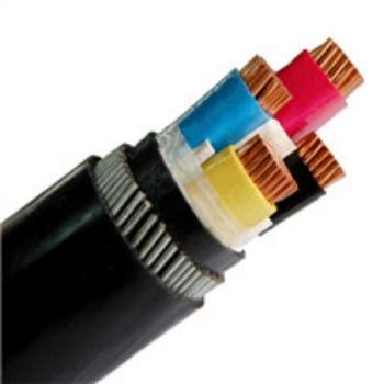
Grabbing the wrong wire gauge off the shelf — or letting a procurement spec slide one size down to save a few dollars per meter — has a way of biting you later. A conductor that’s undersized for the actual load runs hotter, drops more voltage along the run, and in a conduit stuffed with other cables it can trip breakers intermittently or, worse, degrade insulation quietly over months before anything obvious happens. The difference between 2 AWG and 4 AWG isn’t cosmetic.
2 AWG is the larger wire. Its conductor cross-section is approximately 33.6 mm² versus roughly 21.2 mm² for 4 AWG — about 58% more copper. Under NEC 310.15 at 75°C in conduit, 2 AWG copper carries around 130 A compared to 85 A for 4 AWG, and its DC resistance runs roughly 37% lower per meter, meaning less heat and less voltage drop on long circuit runs.
What trips people up is that AWG works backwards — the number goes up as the wire gets smaller, a legacy of how many times rod stock was drawn through a die to reach the final diameter. So “bigger number” means thinner wire, which feels counterintuitive the first dozen times you use the system. Once you understand what’s actually different between these two sizes — in cross-section, in resistance, in how each behaves under load across different installation conditions — the right choice for a given circuit becomes a lot less ambiguous.

AWG Standard Decoded: How the American Wire Gauge Scale Defines Conductor Dimensions
The AWG system traces back to the 1850s wire-drawing industry, where gauge numbers originally described how many times a rod had been drawn through a die. More draws meant a thinner wire — hence the counterintuitive reality that a higher gauge number means a smaller conductor. Once you internalize that logic, the rest of the system becomes mechanical.
The Mathematical Backbone
The governing formula is: d(AWG) = 0.005 × 92^((36−AWG)/39) inches. That exponent is what gives the scale its geometric character. Every 6-gauge step roughly doubles the cross-sectional area; every 3-gauge step multiplies it by about 1.26. Those aren’t approximations to round to — the actual multiplier for 6 steps is closer to 2.0050, which matters when you’re stacking multiple derating factors in a conduit-fill calculation and can’t afford accumulated rounding error.
In practice, this progression means the jump from 4 AWG to 2 AWG — just two gauge steps — delivers a meaningful area increase: roughly 33.6 mm² versus 21.2 mm², a 58% difference in copper cross-section. That is not a marginal upgrade. Two gauge numbers translate directly to a 53% increase in allowable ampacity under NEC 310.15 at 75°C (copper in conduit: ~130 A versus ~85 A). Engineers who treat adjacent gauge steps as interchangeable without checking the numbers tend to find out their mistake during a thermal inspection or, worse, a fault event.
Where 2 AWG and 4 AWG Sit on the Size Ladder
The table below positions both conductors within the range most relevant to distribution panels, feeder runs, and industrial equipment connections. DC resistance values are at 20°C for annealed copper; real installed resistance will shift with temperature, stranding pattern, and alloy purity.
| AWG | Nominal Diameter (mm) | Cross-Section (mm²) | DC Resistance (mΩ/m) |
|---|---|---|---|
| 6 | 4.11 | 13.3 | ~1.35 |
| 4 | 5.19 | 21.2 | ~0.854 |
| 3 | 5.83 | 26.7 | ~0.677 |
| 2 | 6.54 | 33.6 | ~0.537 |
| 1 | 7.35 | 42.4 | ~0.426 |
| 1/0 | 8.25 | 53.5 | ~0.338 |
| 2/0 | 9.27 | 67.4 | ~0.268 |
The resistance figures depend on conductor temper and stranding; expect ±5% or so from one manufacturer’s datasheet to another.
Where AWG Ends: The kcmil Boundary
AWG runs from 40 (hairline instrument wire) down through 0000 (4/0). At 4/0 you hit the practical ceiling — roughly 107 mm² and 211.6 kcmil. Beyond that, the industry switches to kcmil (thousand circular mils), sometimes still written as MCM in older documentation. The transition isn’t arbitrary: at large conductor sizes, the circular-mil unit gives finer resolution than adding more zeros to an AWG designation. If you’re sourcing 350 kcmil or 500 kcmil cable and someone hands you an AWG number, they’ve made an error — or they’re working from a very old spec sheet.
2 AWG and 4 AWG conductors have the same cross-sectional areaFalse
2 AWG has approximately 33.6 mm² cross-section while 4 AWG has approximately 21.2 mm², making 2 AWG roughly 58% larger in cross-sectional area. These are meaningfully different sizes with different ampacity ratings.
IEC Metric Equivalents and Why “Close Enough” Isn’t
International projects — anything governed by IEC 60228 or a national derivative — specify conductors in mm². The closest IEC class 2 conductor to 2 AWG is 35 mm²; the closest to 4 AWG is 16 mm². Neither is a perfect match.
35 mm² is slightly larger than 33.6 mm², which usually means the metric cable passes any NEC ampacity check for 2 AWG service. But the opposite substitution — using a 16 mm² where 4 AWG (21.2 mm²) was specified — leaves you roughly 25% short on conductor area. That gap shows up as higher I²R losses, a narrower derating margin, and a potential NEC violation if the installation is inspected. Engineering sign-off before substituting is not optional on any job I’d put my name on.
The discrepancy also affects terminations. A 35 mm² lug torqued onto a 33.6 mm² conductor may have slightly different contact geometry than the manufacturer tested. Minor, usually — but worth flagging in the documentation.
Stranded vs. Solid: Same AWG, Different Physical Size
Here’s a labeling pitfall that catches people on conduit-fill calculations. A stranded 2 AWG conductor and a solid 2 AWG conductor carry identical cross-sectional copper area, but the stranded version has a larger overall diameter because of the air gaps between individual strands and the outer jacket geometry. Depending on stranding class (Class B, Class C, flexible Class K), the overall diameter can run 5–12% larger than solid for the same AWG. When you’re computing fill for a 1-inch EMT conduit with four 2 AWG THHN conductors, using the solid-conductor diameter from a generic table and actually installing stranded cable can push you over the 40% fill limit. Pull force goes up, insulation abrasion risk increases, and the installation technically fails code compliance.
Always pull the actual cable OD from the specific product datasheet — not a textbook table — before finalizing conduit sizing.
Ampacity and Thermal Ratings: How Much Current Can 2 AWG and 4 AWG Safely Carry?
Current-carrying capacity is where the size difference between these two gauges stops being abstract and starts having real consequences — overheated insulation, nuisance trips, failed equipment, or a fire. The numbers come from NEC Table 310.15(B)(16), which most working electricians just call “the ampacity table,” and they vary depending on conductor material, insulation temperature rating, and how the wire is actually installed.
NEC Ampacity Values: Copper and Aluminum Across All Three Temperature Columns
For copper conductors in a raceway or conduit, the table gives three columns based on insulation temperature rating:
| Gauge | 60°C (e.g., NM-B, TW) | 75°C (e.g., THWN, XHHW) | 90°C (e.g., THWN-2, XHHW-2) |
|---|---|---|---|
| 2 AWG copper | 95 A | 130 A | 150 A |
| 4 AWG copper | 70 A | 95 A | 110 A |
| 2 AWG aluminum | 75 A | 100 A | 115 A |
| 4 AWG aluminum | 55 A | 75 A | 85 A |
The gap is consistent across all columns — 2 AWG carries roughly 35–37% more current than 4 AWG at any given temperature rating.
NEC Table 310.15(B)(16) lists 2 AWG copper ampacity at 130 A and 4 AWG copper at 95 A under the 75°C column for conductors in a raceway.True
These values appear in NEC 310.15(B)(16) for copper conductors, not more than three in a raceway, at 75°C insulation temperature rating, which is the column most commonly applied for standard THWN installations in the United States.
Why the 90°C Column Is Almost Never Fully Usable
Here’s something that trips up newer engineers: just because you pull THWN-2 wire — rated 90°C — doesn’t mean you can use the 150 A value for 2 AWG. NEC 110.14(C) limits conductor ampacity at terminations to the temperature rating of the termination itself, and the overwhelming majority of breakers, lugs, and terminal blocks in U.S. distribution equipment are rated only to 75°C. Some 100 A and below equipment is still 60°C-rated, which is even more restrictive.
In practice, the 90°C column is used mainly as a starting point for derating calculations, not as an operational ceiling. You pull THWN-2 because it gives you headroom when you’re applying correction factors — you derate down from 150 A instead of 130 A. The termination still limits you to the 75°C value once you land the wire.
Conduit Fill, Bundling, and the Derating Math
When more than three current-carrying conductors share a conduit, NEC 310.15(C) requires you to derate ampacity. For four to six conductors the factor is 80%; for seven to nine it drops to 70%. This is where pulling 2 AWG instead of 4 AWG can be the difference between a legal installation and a redesign.
A realistic scenario: you’re running a six-conductor feeder (three phases, neutral, and two equipment grounds don’t count as current-carrying, so assume four current-carrying conductors in the bundle). The 80% derating applies.
- 2 AWG copper at 75°C: 130 A × 0.80 = 104 A allowable
- 4 AWG copper at 75°C: 95 A × 0.80 = 76 A allowable
A 100 A load in that conduit is code-compliant on 2 AWG, over-limit on 4 AWG. Full stop.
Ambient Temperature Correction in Hot Environments
Rooftop conduit runs in summer, engine rooms, industrial ovens, boiler rooms — ambient temperatures above the baseline 30°C (86°F) reduce allowable ampacity per NEC Table 310.15(B)(1). At 46–50°C ambient, the correction factor for a 75°C-rated conductor drops to roughly 0.75.
- 4 AWG at 75°C, corrected: 95 A × 0.75 ≈ 71 A
- 2 AWG at 75°C, corrected: 130 A × 0.75 ≈ 97 A
If your load sits anywhere near 80–85 A and the wire runs through a hot space, 4 AWG that looked adequate on paper becomes undersized in the field. Rooftop HVAC feeders are the most common place I’ve seen this catch people.
The Practical Selection Boundary
At standard conditions — 75°C copper, conduit, no more than three current-carrying conductors, 30°C ambient — 4 AWG is appropriate for loads up to 85 A, and 2 AWG handles loads up to 130 A. That 85–130 A band belongs exclusively to 2 AWG. Once you factor in derating from bundling or elevated ambient, the crossover point shifts downward, and loads that seemed manageable on 4 AWG need to move up. Size for the installed condition, not the catalog page.
Voltage Drop Calculations: Why Resistance Per Meter Determines Wire Choice on Long Runs
Ampacity gets most of the attention in wire sizing discussions, but on runs beyond 20–30 meters, voltage drop quietly becomes the governing constraint. You can have a conductor that’s thermally safe at your load current and still deliver unacceptably low voltage at the load end — and that’s where the resistance difference between 2 AWG and 4 AWG stops being academic.
The Resistance Numbers and What Happens to Them at Temperature
At 20°C, copper 2 AWG runs approximately 0.537 mΩ/m and 4 AWG approximately 0.854 mΩ/m. That 37% resistance penalty on 4 AWG compounds over distance in a straightforward but often underestimated way. What engineers sometimes forget is that these values are handbook figures at 20°C — a conductor running at 60–75°C in conduit on a summer afternoon in a poorly ventilated electrical room is a different story. Copper resistance rises at roughly 0.393% per °C above the reference temperature, so a conductor sitting at 75°C is carrying resistance about 21–22% higher than the datasheet baseline. On a borderline voltage-drop calculation, that shift can push you over the NEC’s 3% guideline even when the room-temperature math looked comfortable.
Copper conductor resistance increases at approximately 0.393% per degree Celsius above 20°CTrue
This follows from the temperature coefficient of resistivity for annealed copper (approximately 0.00393 /°C), a value consistent with IEC 60228 and standard electrical engineering references.
Worked Example: 60 A Load, 50-Meter One-Way Run
Take a real-enough scenario: a 60 A load fed from a panel 50 meters away. Round-trip conductor length is 100 meters.
Using the standard formula — V_drop = I × R_total, where R_total = resistance per meter × total circuit length:
4 AWG: 0.854 mΩ/m × 100 m = 85.4 mΩ total. At 60 A: 60 × 0.0854 = 5.12 V drop.
On a 120 V branch circuit that’s 4.3% — well over the NEC-recommended 3% for branch circuits.
2 AWG: 0.537 mΩ/m × 100 m = 53.7 mΩ. At 60 A: 60 × 0.0537 = 3.22 V drop.
That’s 2.7% on 120 V — passes the 3% guideline with a small but real margin.
On a 240 V feeder, the same absolute voltage drops look very different as percentages: 5.12 V becomes 2.1% and 3.22 V becomes 1.3%. Both gauges pass comfortably, which is why the upgrade from 4 AWG to 2 AWG on 240 V feeders is usually driven by load growth or temperature derating rather than voltage drop alone. Voltage level matters when you’re sitting on a borderline decision.
IEC 60364 Reference for International Projects
For projects outside North America, IEC 60364-5-52 allows up to 4% voltage drop on final circuits. That loosens the constraint somewhat — 4 AWG on the 50-meter/60 A example above would pass at 4.3% only barely, and at elevated conductor temperatures it likely wouldn’t. In practice, specifying to the 3% threshold even on IEC projects gives you margin for temperature rise and load additions that inevitably happen after commissioning. Jinda cables are shipped to customers in more than 50 countries where IEC standards govern the installation, and the conductor resistance values are fully compliant with IEC 60228 Class 2, so the calculations above apply directly to Jinda-supplied product without correction factors.
Quick-Reference Voltage Drop Guide: 2 AWG vs 4 AWG
The table below shows whether each gauge satisfies the NEC 3% guideline on 120 V circuits. “Pass” means calculated drop stays at or below 3%; “Fail” means it exceeds it. Values assume 20°C conductor temperature — derate mentally for hot conduit installations.
| Load Current | 15 m run | 30 m run | 50 m run | 100 m run |
|---|---|---|---|---|
| 30 A — 4 AWG | Pass (0.8%) | Pass (1.5%) | Pass (2.6%) | Fail (5.1%) |
| 30 A — 2 AWG | Pass (0.5%) | Pass (0.9%) | Pass (1.6%) | Pass (3.2%) |
| 60 A — 4 AWG | Pass (1.4%) | Pass (2.8%) | Fail (4.3%) | Fail (8.5%) |
| 60 A — 2 AWG | Pass (0.9%) | Pass (1.8%) | Pass (2.7%) | Fail (5.4%) |
| 90 A — 4 AWG | Pass (1.9%) | Fail (3.8%) | Fail (6.4%) | Fail (12.8%) |
| 90 A — 2 AWG | Pass (1.2%) | Pass (2.4%) | Fail (4.0%) | Fail (8.1%) |
| 120 A — 4 AWG | Pass (2.6%) | Fail (5.1%) | Fail (8.5%) | Fail (17.1%) |
| 120 A — 2 AWG | Pass (1.6%) | Pass (3.2%) | Fail (5.4%) | Fail (10.8%) |
A few things jump out. At 90 A and beyond, even 2 AWG struggles past 30–40 meters on 120 V — you’re looking at moving to 1/0 AWG or reconsidering the voltage level. At 30 A over short industrial runs, either gauge is fine and the decision usually comes down to conduit fill or future load headroom rather than voltage drop. The 60 A/50 m cell is the classic borderline case where getting the gauge wrong produces equipment that runs warm, trips more often than it should, and delivers noticeably degraded performance to motors and controls — consequences that show up months after installation when nobody remembers the original wiring decision.
Physical Dimensions, Weight, and Conduit Fill: Practical Handling Differences Between the Two Sizes
The electrical numbers — ampacity, resistance, voltage drop — get most of the attention in wire selection discussions. But on an actual job site, the physical reality of pulling cable through conduit, bending it around panel knockouts, and supporting it across a cable tray is what determines whether the installation runs on schedule or bleeds overtime hours.
Overall Cable Diameter and Why That 19% Difference Compounds
For stranded THHN/THWN-2 construction, 4 AWG typically lands around 8.3 mm OD and 2 AWG around 9.9 mm OD. That 19% diameter increase sounds modest until you start doing conduit fill math. Area scales with the square of diameter, so the actual cross-sectional footprint of a 2 AWG conductor inside conduit is roughly 42% larger than a 4 AWG conductor — not 19%. That distinction matters every time you’re pulling multiple conductors together.
Conduit Fill: Where Upsizing Forces a Real Cost Decision
NEC Annex C is where this gets concrete. A 1-inch EMT conduit will accept 4 conductors of 4 AWG THHN, which is a common three-phase circuit configuration with a ground. Run 2 AWG THHN in that same 1-inch EMT and you’re down to 3 conductors — you’ve lost the ground, or you’ve lost a phase, depending on how you look at it. The practical resolution is upsizing to 1¼-inch EMT for the 2 AWG run.
That conduit upsize adds material cost: roughly $0.60–$1.20 per foot more for the conduit itself, plus fittings, hangers, and the labor to run a larger pipe through a finished wall or ceiling. On a 150-foot run, that can add $200–$400 in installed cost before you’ve bought a single foot of conductor. It doesn’t always flip the decision back to 4 AWG — if your load demands 2 AWG, you need 2 AWG — but it absolutely belongs in the project budget from day one, not as a change order discovery during rough-in.
A 1-inch EMT conduit can fit 4 conductors of 4 AWG THHN but only 3 conductors of 2 AWG THHN per NEC Annex C fill tables.True
NEC Annex C fill tables are based on conductor OD and the 40% conduit fill rule. The larger OD of 2 AWG THHN (~9.9 mm) reduces maximum conductor count in 1-inch EMT from 4 to 3 compared to 4 AWG THHN (~8.3 mm OD).
Bending Radius and Panel Routing
Larger conductors require larger minimum bend radii, and this becomes genuinely awkward inside crowded panelboards and junction boxes. A stranded 2 AWG cable wants a bend radius in the range of 5–8 times the cable OD depending on insulation type — call it roughly 50–80 mm minimum. In a shallow panel with conductors landing on a 100A breaker near the bottom of the enclosure, that’s not always achievable without careful pre-planning of the wire route before the panel even gets mounted. Four AWG is noticeably more forgiving in tight quarters. Electricians know this intuitively; it’s worth spelling out explicitly when reviewing shop drawings with a contractor.
Weight Per Unit Length: Structural and Logistics Implications
Copper 2 AWG runs approximately 190 kg per kilometer; copper 4 AWG is around 120 kg per kilometer. On a cable tray carrying multiple circuits, that 58% weight difference per conductor accumulates fast. A 30-meter tray section loaded with ten 2 AWG circuits is carrying roughly 57 kg of conductor alone — before tray weight, conduit, or anything else. Structural support spacing calculations need those numbers.
For international procurement, weight per spool also affects freight cost directly. Aluminum conductor versions of both gauges cut that weight roughly in half, which matters on large orders where airfreight or sea freight rates are calculated by gross weight or volumetric weight, whichever is greater.
Jinda manufactures both gauges in stranded and solid constructions, available with PVC, XLPE, or EPR insulation depending on application environment. Standard spool sizes are configured to reduce short-end waste on large project orders — a detail that rarely gets discussed but shows up clearly when you’re reconciling material takeoffs against delivered quantities on a multi-building industrial site.
Common Applications Mapped to Each Gauge: Matching Wire Size to Real Electrical Systems
Getting the gauge right before you order saves you from the worst kind of rework — pulling cable you’ve already terminated and conduit-filled. Here’s how each size actually gets used in the field.
Where 4 AWG Belongs
The 60 A subpanel feeder is the classic home for 4 AWG. A detached garage panel, a workshop subpanel, a dedicated HVAC disconnect — these are the bread-and-butter 4 AWG jobs, and the ampacity headroom at 85 A (75°C copper, conduit) fits comfortably with a 60 A breaker’s continuous load requirements.
Level 2 EV charging is worth calling out specifically. A 48 A continuous circuit — the maximum for a 60 A breaker under NEC’s 80% rule — sits right at the edge of what 4 AWG handles. Most residential Level 2 EVSE units running at 40 A or below are fine on 4 AWG, but if the homeowner is already asking about a future 80 A charger, don’t install 4 AWG. The upsizing cost at rough-in is trivial compared to re-pulling later.
Smaller commercial HVAC compressors, typically in the 3–5-ton range depending on the unit’s minimum circuit ampacity nameplate, often land in 4 AWG territory. Same story for service entrance on a small welding shop or machine shop with modest demand — if the utility meter is feeding a 60 A main breaker, 4 AWG works. Solar PV string combiner output conductors at moderate collection currents (say, 40–55 A continuous after the 125% PV multiplier) also fit here, though the specific wire sizing depends on conduit fill, ambient temperature, and whether you’re in direct sun exposure on a rooftop.
Where 2 AWG Is the Right Call

The 100 A residential service entrance is almost synonymous with 2 AWG copper. A 100 A main panel in a single-family home — still extremely common in older housing stock — runs 2 AWG service entrance conductors from meter to panel. That 130 A rated capacity under the 75°C column gives real margin when the panel is pulling sustained load in summer.
Industrial motor branch circuits in the 25–40 hp range at 460 V three-phase push you solidly into 2 AWG. The full-load current on a 30 hp, 460 V motor runs roughly 40 A, and with NEC’s 125% continuous load factor and motor branch circuit sizing rules, 2 AWG is typically what the calculation produces. Try to run that circuit on 4 AWG and you’ll be violating code before the motor even sees a hard start.
For EV charging, commercial Level 2 stations rated at 80 A continuous require 2 AWG minimum. These installations — parking structures, fleet charging depots — are increasingly common, and procurement teams ordering in quantity should be specifying 2 AWG from the outset.
Backup generator interconnects, marine shore power cables at 50 A/240 V, and data center PDU branch feeders share a common thread: moderate-to-high continuous current in environments where thermal management actually matters. On a vessel, you don’t want marginal wire running hot in a sealed conduit run below deck. In a data center, a warm cable is wasted cooling load.
Battery and Energy Storage: Voltage Changes Everything
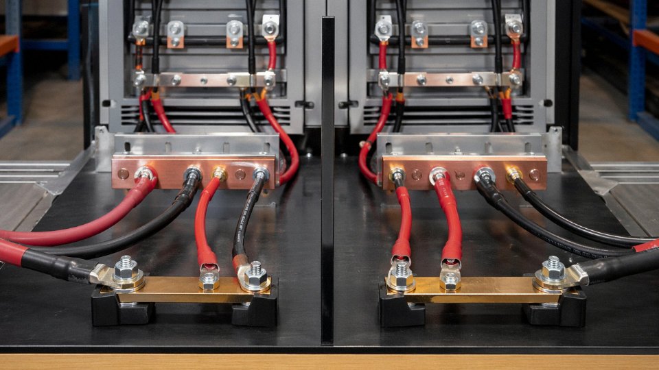
This catches designers who are new to low-voltage DC systems. In a 48 V lithium battery bank — telecom backup, off-grid renewable storage, EV battery modules — a 4 kW load draws roughly 83 A. That’s past 4 AWG’s safe continuous rating and well within 2 AWG’s capacity. Even a 3 kW load at 48 V pulls about 62 A continuous, which puts you right at 4 AWG’s limit with no margin. The lower the system voltage, the sooner the conductor upgrade happens.
In 48 V DC battery systems, a 4 kW load requires approximately 83 A, which exceeds 4 AWG's NEC 75°C ampacity of 85 A with no derating margin remaining.True
At 48 V, current equals watts divided by volts: 4000 W ÷ 48 V = 83.3 A. NEC 310.15 rates 4 AWG copper at 85 A in the 75°C column for conduit installation before any derating for temperature, fill, or continuous load factors, leaving essentially zero usable margin.
Welding Cable: Don’t Confuse Duty Cycle With Steady State
Both gauges show up in welding lead assemblies, but the duty cycle question separates them. A light-duty MIG setup running 200–250 A at 20–30% duty cycle might be built on 4 AWG flexible welding cable with acceptable temperature rise given the cooling intervals. Heavier industrial welding — stick electrodes, larger MIG guns, plasma cutting machines running longer arcs at 300 A and above — needs 2 AWG flexible welding cable. The fine-stranded Class 5 construction in welding cable handles the repeated flexing; the conductor mass handles the heat.
International Projects and Metric Equivalents
Jinda’s export production covers both AWG sizes manufactured to IEC 60228 Class 2 (solid or stranded for fixed installation) and Class 5 (flexible) stranding. In practice, project tender documents in the Middle East, Southeast Asia, Africa, and much of Europe specify metric cross-sections: 4 AWG is typically quoted as 25 mm² in tender docs, and 2 AWG as 35 mm². Neither is an exact conversion — 4 AWG is closer to 21.2 mm² and 2 AWG to 33.6 mm² — so procurement engineers reviewing international specs should confirm whether the tender’s mm² figure is the nominal IEC size or a true geometric equivalent, because that difference can affect ampacity compliance under IEC 60364 or local grid codes.
Material Cost, Copper Weight, and Total Installed Cost Comparison for Budget Planning
Copper content is where the cost story starts. Because 2 AWG carries roughly 58% more cross-sectional area than 4 AWG — about 33.6 mm² versus 21.2 mm² — you’re pulling meaningfully more metal through every meter of cable. At current LME copper prices in the USD 9–10/kg range (spot price fluctuates; check before locking in a BoQ), that difference on a 1 km single-conductor run works out to somewhere around USD 630–700 in raw copper alone, before manufacturing overhead, insulation, or any margin gets added. On a 50 m branch circuit that number barely registers. On a 2 km feeder for an industrial facility, it becomes a real line item.
On a 1 km run, 2 AWG contains approximately 58% more copper by weight than 4 AWG, resulting in a raw material cost premium of roughly USD 630–700 at USD 9–10/kg copper pricing.True
This follows directly from the cross-sectional area difference (33.6 mm² vs 21.2 mm²), copper density of approximately 8.96 g/cm³, and the stated copper price range. The figure is a valid first-order estimate, subject to actual market pricing and stranding geometry.
Why Conductor Price Is Only Part of the Number
The mistake I see most often in preliminary budgets is treating cable cost as the total installed cost. It isn’t close. Once you account for conduit — and 2 AWG may push you from 3/4″ to 1″ trade size depending on fill calculations and how many conductors share the raceway — plus fittings, wire lugs, compression connectors, pulling compound, and the actual labor hours to install it, the conductor material typically represents somewhere between 25% and 45% of what you actually spend. Labor alone usually lands in the 40–60% range of total installed cost, depending on the plant, the union scale or local rates, and how congested the cable tray or conduit run is.
That math has a practical consequence: a USD 700 copper premium on a feeder run that costs USD 8,000–12,000 fully installed is less than 10% of the project line item. Specifying down to save that money is rarely the right call if the electrical load genuinely warrants 2 AWG.
The Hidden Cost of Under-Sizing
Under-sizing is where projects quietly lose money — sometimes a lot of it. A 4 AWG circuit that runs at or beyond its thermal limit doesn’t just shorten insulation life; if it trips a breaker repeatedly or eventually fails, you’re looking at a conduit re-pull (which means accessing the raceway, often above a production line or inside a finished wall), potential drywall or tray cover repair, a compliance re-inspection, and any downtime the failure caused. In a food processing or pharmaceutical facility, that downtime cost alone can dwarf the original cable budget. The upfront premium for correct sizing is almost always cheaper. Usually by a wide margin.
Aluminum as a Legitimate Cost-Reduction Path
For large feeder runs — think 200 A+ service entrances, main distribution feeders, or long utility tie cables — aluminum deserves a serious look. Aluminum 2 AWG has ampacity broadly comparable to copper 4 AWG under certain installation conditions, and the material cost per kg runs roughly 60% lower than copper, with the added benefit of meaningfully lower weight per meter (which matters when you’re pulling 300 m through a tray system). The trade-offs are real and non-negotiable: aluminum terminations rated for aluminum conductors, anti-oxidant compound applied at every connection, and an inspection cadence that accounts for the creep and oxide layer issues that aluminum is known for. It’s a valid engineering choice for the right application. It is not appropriate for branch circuits, high-vibration environments, or anywhere the termination quality can’t be reliably maintained.
Procurement Planning and Volume Agreements
For international EPC contractors or factory owners running multi-phase builds, the per-unit cable price is rarely the biggest procurement risk — schedule and price volatility are. Copper swings of 15–20% inside a 12-month project window are not unusual, and they can blow a materials budget that was locked in at tender. Fixed-price framework agreements with volume commitments can hedge that exposure. Jinda supplies both copper and aluminum conductor cables across high-volume project quantities and offers framework pricing structures designed specifically for EPC contractors and international buyers who need budget certainty across multi-year programs — the kind of arrangement where you agree on gauge specifications, delivery schedule, and pricing basis upfront, rather than re-quoting every purchase order against a moving spot market.
Code Compliance and Safety Standards: NEC, IEC, and International Certification Requirements
The electrical performance gap between 2 AWG and 4 AWG only matters if your installation is code-compliant. A conductor that passes current without tripping a breaker is not the same as one that satisfies the authority having jurisdiction — and on international projects, those two things can be very far apart.
NEC Articles That Govern These Gauges in Practice
Article 310 is where most engineers live when sizing conductors. Table 310.15(B)(16) — the 75°C copper column under conduit conditions — gives you roughly 130 A for 2 AWG and around 85 A for 4 AWG. Those are the ceiling figures before any derating for conduit fill, ambient temperature above 30°C, or continuous loads. Continuous loads (anything running more than three hours) require the conductor ampacity to be sized at 125% of the load current, which in practice pushes a lot of 85 A nominal circuits up to 4 AWG being marginal and 2 AWG being the safer call.
Article 215 covers feeder conductors — the runs between the service panel and downstream distribution panels. 4 AWG appears frequently in residential and light commercial feeders serving 60–70 A subpanels; 2 AWG is the more common choice when the downstream panel demand pushes into the 90–110 A range. Article 230 governs service entrance conductors, where 2 AWG is regularly specified for 100 A residential services, though local utilities sometimes impose stricter minimums regardless of what the NEC allows. Article 210 branch circuit rules are less likely to place either gauge at the terminal end of a circuit, but they do affect the feeder sizing that feeds the panels those branch circuits originate from.
Overcurrent Protection: What NEC 240.4 Actually Requires
NEC 240.4(D) restricts overcurrent protection for small conductors — specifically 18 AWG through 10 AWG. Both 4 AWG and 2 AWG sit above that restricted range, so you are not locked into a fixed maximum breaker size by that subsection alone. What governs you instead is the ampacity from Table 310.15 under your specific installation conditions. If derating for four current-carrying conductors in a conduit in a 40°C ambient drops your 2 AWG effective ampacity to, say, 104 A, the overcurrent device must not exceed that derated value unless a higher standard next-size-up rule applies under 240.4(B). In practice, many installers forget the derating step entirely and size the breaker to the table value. That is how conductors run hotter than designed for years without tripping anything — until an insulation failure or a fire.
IEC 60364 and Installation Method Derating
Outside North America, IEC 60364 Part 5-52 is the governing framework for wiring system selection. The current ratings assigned to a given conductor cross-section vary substantially depending on Reference Installation Method — clipped direct to a surface (Method B2), in conduit on a wall (Method A), in free air (Method F), and so on. A 35 mm² conductor (close to 2 AWG’s 33.6 mm²) might be rated anywhere from roughly 110 A to over 170 A depending on which method applies. This means a procurement specification that says only “2 AWG equivalent” or “35 mm²” without specifying the installation method is technically incomplete. Project engineers working across jurisdictions need to nail down the installation method before finalizing conductor cross-section.
IEC 60364 Part 5-52 installation method ratings for the same conductor size can vary by 40–50% depending on how the cable is installed.True
IEC 60364-5-52 tables show that the same conductor cross-section carries significantly different current ratings under Method A (enclosed in conduit in thermally insulating wall) versus Method F (free air), due to differences in heat dissipation. This range is well-documented in the standard's reference tables.
Product Certifications for North American, European, and Export Markets
For North American projects, the insulation system certification matters as much as the conductor gauge. UL 83 covers THHN and THWN-2 insulation — the most common type you will see on 2 AWG and 4 AWG building wire in the US. UL 44 covers XHHW and XHHW-2, used where 90°C wet rating or better mechanical durability is needed. Canadian projects require CSA certification; many large-volume manufacturers produce dual-listed UL/CSA product, but verify the specific certification mark on the reel label rather than assuming.
European installations typically require CE marking and, depending on the application — transit, data centers, public buildings — LSZH (low smoke zero halogen) insulation to EN 50525-3-11 or similar. The difference in jacket compound matters operationally: standard PVC-jacketed 4 AWG equivalent cable can release hydrogen chloride in a fire, which is why LSZH specs exist and why substituting standard PVC on a project that calls for LSZH is a compliance failure, not just a materials preference.
Export markets add further layers. SABS certification is required for South Africa; SIRIM covers Malaysia; Gulf Cooperation Council projects often specify IECEE CB Scheme test reports as a baseline for product acceptance, with the project owner’s engineer deciding whether additional local certification is needed on top.
Where Jinda’s Credentials Fit Into This Framework
Jinda manufactures conductors to IEC 60228 stranding classes, which defines the conductor construction — Class 1 (solid), Class 2 (stranded), Class 5 (flexible) — that underpins the mechanical and electrical performance guarantees. ISO 9001 certification covers the quality management system, meaning process controls, inspection records, and traceability are documented rather than assumed. For international project owners who require third-party verification, Jinda can support factory inspection arrangements, furnish material test reports and conformance certificates, and provide the export documentation package that procurement managers typically need for customs clearance and project owner approval on large supply contracts.
Termination Hardware, Lugs, and Connector Compatibility for 2 AWG and 4 AWG Conductors
The conductor itself is only half the story. A perfectly sized 2 AWG cable run can fail at the first terminal if the hardware connecting it wasn’t selected for that gauge. This is one of those areas where experienced electricians rarely make mistakes — but engineers specifying equipment from an office, or crews upgrading an existing system from 4 AWG to 2 AWG mid-project, get caught out more often than the industry likes to admit.
Terminal and Lug Ratings Are Not Suggestions
Every terminal block, circuit breaker lug, disconnect switch, and bus bar connector carries a marked conductor range — something like “14 AWG–2 AWG” or “4 AWG–350 kcmil.” That range exists because the terminal body, its contact surface area, and its clamping geometry were all tested to UL standards within those limits. Inserting a 2 AWG conductor into a terminal rated for 4 AWG maximum is a code violation under NEC 110.14 regardless of whether the conductor’s ampacity would otherwise be acceptable. The mechanical mismatch is the issue: the larger conductor can’t seat properly, the clamping force distributes unevenly, and you get elevated contact resistance that generates heat. That’s not a theoretical risk — thermal imaging surveys on industrial panels routinely flag exactly this failure mode, and the heat signature appears at the lug, not in the cable itself.

Compression Lugs and Die Set Discipline
For compression (crimp) lugs, 2 AWG and 4 AWG are not interchangeable on the same die set. A 2 AWG copper compression lug requires a die producing a larger hex geometry — typically in the range of a #2 or equivalent die index depending on the tool manufacturer (Burndy, Ilsco, and Thomas & Betts all use slightly different indexing, which creates real confusion in the field). Using the wrong die leaves voids in the crimp barrel. Those voids increase contact resistance — even a small air pocket measurably raises the joint’s resistance relative to a full-compression crimp — and the joint passes visual inspection. You won’t find it until a thermal camera picks up a hot spot, or until the lug eventually fails under load cycling.
The practical rule: label your die sets, store them by gauge range, and never assume a “close enough” crimp is acceptable on conductors carrying significant current. On any installation running near rated ampacity, this matters.
Using a compression die sized for 4 AWG on a 2 AWG conductor produces a mechanically and electrically acceptable crimp.False
An undersized die cannot fully compress the larger conductor barrel, leaving voids that increase contact resistance, generate heat under load, and represent a latent failure point detectable only by thermal imaging or eventual burnout.
Mechanical Lug Torque: Use a Calibrated Tool
Set-screw (mechanical) lugs have published torque specifications that differ by gauge. A standard two-hole mechanical lug for 2 AWG typically calls for roughly 45–50 in-lb; the equivalent 4 AWG lug usually specifies around 35–40 in-lb. These aren’t arbitrary — under-torque leaves the conductor loose enough to vibrate and arc; over-torque can crack the lug body or damage strands. NEC 110.14(D) now explicitly requires installers to follow manufacturer torque instructions, and in practice that means a calibrated torque screwdriver or torque-limiting driver, not hand feel. Most experienced crew members overestimate how tight “tight enough” actually is.
Splicing: Wire Nuts Stop at 4 AWG
This surprises people upgrading a system. Wire nuts are not UL-listed for conductors larger than 4 AWG in most product families — the 4 AWG wire nut is already the upper end of the range for common brands. Splicing 2 AWG conductors in a junction box requires a listed split-bolt connector, a polaris-type multi-tap connector, or a compression splice sleeve. All three are acceptable; the split-bolt is cheapest but requires careful tape work (three half-lapped layers of vinyl, then a layer of self-amalgamating tape is a reasonable minimum); polaris connectors are faster and produce a more reliable insulated joint in tight enclosures.
Verify Panel Terminal Ratings Before You Order Wire
Before finalizing gauge selection on any retrofit or new feed, pull the panel schedule or equipment nameplate and confirm the listed conductor range. A main lug rated “4 AWG–2/0 AWG” accepts both gauges without issue. A lug rated “6 AWG–1/0 AWG” technically accepts 2 AWG as well. But if a terminal is marked for a specific maximum that excludes 2 AWG, you need written confirmation from the equipment manufacturer before proceeding — not a field judgment call. On service upgrades especially, discovering a terminal incompatibility after the cable is pulled adds real cost: at minimum a lug kit replacement, potentially a full terminal block assembly, and in some panel designs, equipment downtime while you wait for parts.
Get the terminal datasheet before you pull the wire. It’s a five-minute check that avoids a half-day fix.
Frequently Asked Questions About 2 AWG and 4 AWG Wire Selection
Is 2 AWG or 4 AWG better for a 100 A service?
For a standard 100 A residential service entrance, 2 AWG copper is the correct choice under NEC 310.15. Full stop. The 75°C ampacity of 4 AWG copper in conduit is 85 A — that’s already below the 100 A overcurrent device, which means you’d be relying on a conductor that cannot legally carry the full rated load without a formal derating analysis, engineering sign-off, and in most inspected jurisdictions, a conversation with the AHJ that you probably don’t want to have. Some inspectors will reject it outright. The practical answer is: spec 2 AWG, move on, and don’t create a compliance problem to save a few meters of copper.
4 AWG copper (85 A at 75°C) is undersized for a 100 A service entrance and requires engineering approval to use in most NEC jurisdictionsTrue
NEC Table 310.15(B)(16) lists 4 AWG copper at 85 A under the 75°C column for conductors in conduit. A 100 A overcurrent device exceeds this value, making 4 AWG a code violation in standard residential service entrance applications without a specific engineering deviation.
Can I use 4 AWG aluminum instead of 2 AWG copper to save money?
This substitution comes up constantly in procurement discussions, and the numbers don’t support it. Aluminum 4 AWG runs about 75 A at 75°C — actually lower than copper 4 AWG, so it gets you further from the requirement, not closer. Aluminum 2 AWG at 90 A (75°C) is a better comparison point against copper 4 AWG, and that substitution does work in many feeder applications — but it comes with conditions. Aluminum requires AL-rated terminations at both ends, anti-oxidant compound in most field practices (check your local code adoption on that), and minimum 75°C-rated terminals. If the panel or disconnect was only listed for copper, you have a problem regardless of conductor size. Check the equipment listing before you order anything.
What is the metric equivalent of 2 AWG and 4 AWG?
For IEC projects, 2 AWG maps most closely to 35 mm² under IEC 60228. For 4 AWG, it depends on stranding class — 25 mm² is the closer match by cross-section for Class 2 stranded, though some engineers use 16 mm² when stranding flexibility isn’t a factor. The important caveat is that ampacity tables under IEC installation methods (particularly IEC 60364 Method B or C) will give different values than NEC 310.15, so a straight dimensional substitution isn’t enough. You need to confirm the current rating under the specific installation method used on the project, or you risk undersizing even when the mm² looks right on paper.
How do I tell 2 AWG from 4 AWG wire already installed in a building?
Start with the jacket. Under NEC 310.120, conductors 6 AWG and larger must be marked with the wire size, voltage rating, insulation type, and manufacturer on the outer surface — the print legend runs along the length of the cable and should be readable with a flashlight even in a tight conduit section. If the jacket is abraded, painted over, or simply too old to read (and this happens more than anyone wants to admit), pull out a micrometer and measure the bare conductor diameter. 2 AWG runs roughly 6.54 mm across, 4 AWG around 5.19 mm. A decent wire gauge wheel tool works in the field. Don’t guess based on color or feel.
Does wire gauge affect the circuit breaker size I must use?
Yes, and this is one of the areas where field errors cause real problems. The breaker protects the wire, not just the load. NEC Table 310.15 allows a maximum 150 A overcurrent device for 2 AWG copper THWN-2, and 110 A for 4 AWG. In practice, though, the breaker you actually install must not exceed the lower of the conductor ampacity or the equipment’s listed terminal rating. A 2 AWG conductor feeding a 100 A panel with 75°C terminals gets a 100 A breaker — not 150 A — because the terminal rating governs. Getting this sequence wrong is how conductors overheat at connection points while the breaker sits there doing nothing.
Is 2 AWG overkill for a 60 A sub-panel feeder?
Thermally, 4 AWG is sufficient for 60 A. But thermal sufficiency isn’t the whole story. On runs longer than roughly 40–50 meters (and this threshold shifts depending on load power factor and whether you’re targeting 3% or 5% voltage drop), the resistance difference between the two gauges — 0.537 mΩ/m for 2 AWG versus 0.854 mΩ/m for 4 AWG — pushes 4 AWG past the voltage drop limit before you reach the end of the run. The voltage drop section of this article walks through the specific calculation. The short version: if your sub-panel run is short, 4 AWG is fine. If it’s crossing a warehouse or running down a long equipment row, check the math before you assume 4 AWG qualifies.
How to Source 2 AWG and 4 AWG Cable for International Projects: Quality Assurance and Supply Chain Guidance
Getting the electrical specification right is only half the job. The other half is making sure the cable you receive actually matches what you specified — and in international procurement, those two things diverge more often than anyone likes to admit.
Nail the Specification Before You Send Any RFQ
Vague purchase orders are where cable projects go wrong. Before contacting any supplier, buyers need to lock down several parameters that directly affect electrical performance, code compliance, and installation behavior.
Conductor material is the starting point: copper versus aluminum changes ampacity, termination hardware, and long-term reliability completely. For most of the applications where 2 AWG and 4 AWG appear — panels, feeders, EV charging infrastructure, marine runs — copper is the default, but specifying this explicitly avoids misunderstandings on high-volume orders.
Stranding class matters more than most procurement managers realize. Solid conductors don’t exist at 2 AWG in practical terms, but the distinction between Class 2 (compressed stranded, the standard for THHN/THWN-2 and most building wire) and Class 5 (flexible, fine-wire stranding used in portable cords and machine tool wiring) affects conductor diameter, flexibility, and which lugs you can crimp. Getting this wrong means the cable arrives on site and won’t terminate properly into the hardware already installed.
Insulation material and voltage rating need to be stated together. THHN/THWN-2 with PVC insulation and nylon jacket is the North American standard. XLPE with PVC oversheath covers a lot of European and industrial applications and handles higher operating temperatures — typically 90°C versus 75°C for standard THHN. Specify the voltage class too: 600 V for most building-wire applications, 1 kV for many industrial and utility feeders.
Jacket color coding is country-specific and non-trivial for multi-country projects. NEC installations use black, red, and blue for ungrounded conductors, white or gray for neutral, green or bare for ground. IEC-influenced markets use brown, black, and gray for line conductors, blue for neutral, and green-yellow for protective earth. If you’re shipping cable to a project that spans both code environments, you either need two separate purchase orders or a clear written agreement on which standard governs each shipment.
State the required certification marks explicitly: UL 83 and UL 44 for North America, CE marking and CPR reaction-to-fire class for Europe, and destination-country marks like SASO (Saudi Arabia), INMETRO (Brazil), or SNI (Indonesia) for other markets. A cable that passes IEC tests but lacks the specific third-party mark required at the border can be held in customs for weeks.

What a Meaningful Factory Audit Actually Covers
Visual inspection at a cable factory is nearly useless as a quality gate. The things that distinguish compliant cable from substandard product happen inside the process, not on the finished reel.
Ask to review conductor drawing and annealing records. Under-annealed copper is harder and more brittle — it passes visual and dimensional checks but cracks at terminations after thermal cycling in service. Insulation extrusion line calibration logs tell you whether wall thickness is being held within tolerance across the full run, not just at the ends where factory QC typically samples. Spark test records and high-voltage withstand test logs should be continuous, reel-by-reel, not sampled. Any supplier that can’t produce these records routinely is telling you something.
Third-party sample testing is worth the cost on any order above roughly 10,000 meters. Pull samples from mid-reel — not from the end footage that’s easy to swap — and send them to an independent lab for DC resistance measurement and conductor cross-section verification. It’s not uncommon to receive 2 AWG cable with a conductor cross-section closer to 30 mm² than 33.6 mm², which shifts resistance upward and ampacity downward in ways that won’t show up until the cable runs hot under sustained load.
Jinda conducts 100% spark testing and high-voltage withstand testing on every reel of finished cable before shipment.True
This is a standard documented QA practice at Jinda's production facilities, consistent with IEC 60502 and UL manufacturing process requirements for power cable. Continuous reel-by-reel testing is what separates ISO-certified production lines from batch-sampling operations.
Lead Times, Spool Lengths, and Inventory Planning
Standard 2 AWG and 4 AWG cables in THHN/THWN-2 and XLPE constructions are available from Jinda’s inventory in 100 m, 305 m (1,000 ft), and 500 m spool lengths. For straightforward orders in standard colors and constructions, lead times from Jinda’s warehoused stock typically run 1–2 weeks including documentation preparation and freight booking.
Custom requirements — non-standard colors, special insulation compounds, armored constructions, unusual voltage ratings — move to a production lead time of roughly 3–6 weeks, depending on order volume and current line scheduling. That range widens during peak demand periods, usually Q3 and early Q4 when EPC contractors are closing out annual project budgets. If your project has a hard commissioning date, build buffer into the procurement schedule and communicate your timeline early.
EPC contractors and utilities running multi-year programs can structure blanket purchase orders or VMI (vendor-managed inventory) arrangements, which shift the forecasting burden off the buyer’s procurement team and keep buffer stock staged closer to the project.
Export Documentation: What to Require as Standard
International cable shipments generate paperwork that can delay projects just as effectively as a manufacturing problem. At minimum, require: cable test reports to IEC 60332-1 or -3 (flame retardance, depending on installation type), IEC 61034-2 (smoke emission for LSZH constructions), and IEC 60754 (halogen content) where LSZH is specified. For freight purposes, get packing lists with individual reel weights and dimensions — freight forwarders need this to calculate sea freight rates accurately, and missing data here causes last-minute delays at the port. Certificate of origin is required for customs clearance in most markets and is necessary for preferential tariff treatment under various trade agreements.
Jinda provides a complete export documentation package as standard for international orders, including test reports, packing lists, certificates of origin, and material safety data sheets where applicable.
Why Manufacturing Depth Matters for Long-Term Supply
A supplier with a single production line is a supply-chain risk. Jinda has operated since 1987 — long enough to have weathered raw copper price spikes, regulatory changes across multiple export markets, and the supply disruptions that periodically hit international logistics. Five production bases across China totaling 470,000 m² of manufacturing space, with over 1,000 employees spanning R&D, production, QA, and technical support, means that capacity constraints on one line don’t automatically become your project’s problem. Active supply relationships in more than 50 countries have required Jinda to build real fluency in divergent certification regimes and documentation requirements — which is genuinely useful when your project spans multiple code environments or jurisdictions.
For buyers who need a cable supplier that can quote accurately, ship consistently, and support technical questions after the order is placed, that organizational depth is the practical case for a long-term supply agreement rather than spot purchasing.