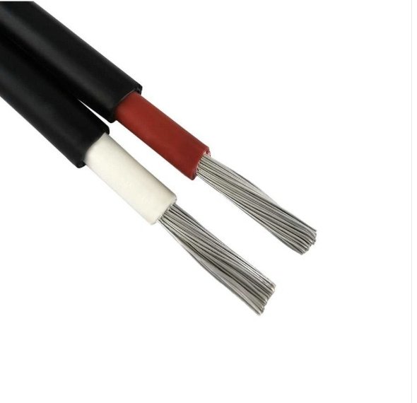
Touching the wrong wire in a junction box — or worse, connecting mismatched cables into a panel — is the kind of mistake that turns a routine maintenance job into an arc flash incident, a scrapped batch, or a week-long production halt. The frustrating part is that low-voltage wiring doesn’t always look any different from medium- or high-voltage wiring once it leaves the factory and gets bundled, re-routed, or re-labeled by three different electricians over a decade. Missing the identification costs real money: downtime on a single automated line can run anywhere from a few hundred to several thousand dollars per hour depending on the process, and a misconnected cable that damages a drive or PLC can add weeks to the repair timeline if the replacement part is on back-order.
A wire is generally classified as low voltage if it operates at or below 1,000 V AC (or 1,500 V DC) per IEC 60038. In practice, you identify it by checking insulation color codes against the wiring standard for your region — blue neutral, green-yellow ground, and brown live under IEC; white neutral, bare/green ground, and black or red hot under NEC — then confirming with a multimeter set to the appropriate AC or DC voltage range.
What trips people up is that color codes shift depending on whether the installation was built to IEC or NEC standards, and older sites often mix both. A brown wire in a European machine is a live conductor; on a North American retrofit job, that same brown might have been used as a spare control wire at 24 V DC. Neither the color nor the wire gauge alone tells the whole story — and that gap between assumption and verification is exactly where problems start.

Voltage Classification Systems: What ‘Low Voltage’ Actually Means Across Different Standards
The phrase “low voltage” gets thrown around constantly on the plant floor, in procurement specs, and in electrical codes — and it rarely means the same thing twice. An HVAC controls tech calling a thermostat wire “low voltage” is talking about 24 V. An IEC-trained engineer reviewing a 480 V three-phase distribution panel is also, technically, talking about low voltage. Both are correct within their own frameworks. That disconnect causes real problems when specs get written, cables get sourced internationally, or a maintenance crew assumes “low voltage” means something benign.
IEC 60038: The International Reference Point
IEC 60038 divides voltage ranges into three bands that most of the world outside North America uses as a baseline.
Extra-low voltage (ELV) covers systems up to 50 V AC or 120 V DC. This is the realm of door intercoms, landscape lighting, certain instrumentation loops, and battery-backed control circuits. Shock risk at these levels is real but low for dry-skin contact — though 50 V DC through a wet hand or across the chest is not trivial.
Low voltage (LV) runs from 50 V AC up to 1,000 V AC (or 1,500 V DC). That’s an enormous range. A 230 V household circuit sits here. So does a 690 V industrial motor feed. The IEC 1,000 V ceiling is what Jinda’s standard power cables are rated against — the 0.6/1 kV designation on a cable jacket means the conductor-to-ground insulation is rated for 0.6 kV and conductor-to-conductor for 1 kV, both per IEC 60502.
High voltage (HV) starts above 1,000 V AC. Distribution feeders, substation transformers, overhead transmission — that territory.
NEC Article 725: Why American Electricians Mean Something Completely Different
Under the National Electrical Code, “low-voltage wiring” almost always refers to Article 725 Class 2 circuits, which are limited to roughly 30 V and 100 VA. Fire alarm wiring, security systems, audio/visual cabling, thermostat wire — that’s the world Article 725 governs. Class 1 circuits go up to 600 V but are treated more like standard power wiring in terms of installation requirements. Class 3 sits between Class 2 and Class 1 with slightly relaxed power limits.
The practical hazard: an American electrician says “that’s low-voltage wire, don’t worry about it” — and they might mean 24 V Class 2 thermostat cable. A European engineer hears the same sentence and mentally files it under “anything up to 1,000 V.” Get both people working on the same international project without a vocabulary check and you have a live misunderstanding.
OSHA’s Worker Protection Definition
OSHA 29 CFR 1910.303 doesn’t redefine voltage bands so much as establish minimum safe-work rules for systems above 50 V, which is where mandatory insulation, guarding, and lockout/tagout requirements kick in. From an OSHA standpoint, 50 V is effectively the floor of concern — below that, the rules relax considerably.
Comparison Table
| Standard | LV Upper Limit (AC) | LV Upper Limit (DC) | Typical Applications |
|---|---|---|---|
| IEC 60038 | 1,000 V | 1,500 V | Industrial motors, distribution panels, building power |
| NEC Article 725 (Class 2) | ~30 V | ~60 V | Thermostats, security, AV, BAS controls |
| NEC Article 725 (Class 1) | 600 V | 600 V | Industrial control circuits |
| OSHA 29 CFR 1910.303 | 50 V (threshold of regulation) | 50 V | Worker protection boundary |
| IEC ELV | 50 V | 120 V | Instrumentation, landscape, intercoms |
Low Voltage Does Not Mean Safe Voltage
This is worth saying plainly: a 480 V three-phase circuit is low voltage under IEC 60038. It will kill you. The classification describes insulation and equipment design parameters, not the severity of a shock. A 480 V contact through the hand-to-hand path delivers roughly the same cardiac fibrillation risk as anything else above about 100 V — the “low” label is an engineering taxonomy, not a safety rating.
IEC 60038 low voltage classification (up to 1,000 V AC) does not imply low shock hazard — 480 V three-phase circuits fall within the LV band and remain lethal.True
IEC 60038 categorizes voltage bands for equipment design and insulation purposes. The 1,000 V AC upper limit for LV reflects cable and switchgear rating conventions, not physiological safety thresholds. OSHA and IEC both treat anything above 50 V as requiring protective measures.
How Jinda Cable Voltage Designations Map to These Standards
Jinda marks cables with designations like 300/500 V and 0.6/1 kV per IEC 60227 (for flexible and fixed wiring cables) and IEC 60502 (for extruded solid dielectric power cables). The first number is the rated voltage conductor-to-earth; the second is conductor-to-conductor. A 300/500 V cable — typical for light wiring and control applications — sits comfortably within the IEC ELV-to-LV transition zone. A 0.6/1 kV cable is the workhorse of industrial LV distribution. When you’re reading a procurement spec or checking a cable reel, these printed designations are your first hard data point on where the wire sits in the IEC classification system — not the color, not the size, not what someone told you on the job site.
Visual Inspection Checklist: Cable Jacket Color, Printing, and Physical Clues
Before you reach for a multimeter, spend two minutes looking at the cable itself. A surprising amount of information is printed, molded, or built right into the construction — if you know what to read.
Conductor Color Coding by Region
Color codes are your first clue, but only if you know which standard applies to the installation you’re looking at.
Under NEC (US and Canada): black or red conductors are ungrounded “hot” lines, white or gray is neutral, and green or bare copper is the equipment ground. Straightforward enough for a domestic or light-commercial job wired after the mid-1990s.
IEC harmonized wiring — used across the EU, most of Asia, Africa, and a growing portion of the Middle East — flips that around: brown is live, blue is neutral, and the bi-color green-yellow stripe is protective earth. If you’re commissioning equipment sourced from Europe and integrating it into a North American panel, that color mismatch has caused more than one misconnection on the shop floor.
Older UK installations (pre-2004) used red for live, black for neutral, and green or green-yellow for earth. Legacy buildings sometimes have both old and new wiring in the same trunking after a partial rewire. Treat any pre-2004 British installation as an unknown and verify with instruments regardless of what color you think you’re seeing.
One hard rule: color alone cannot confirm voltage class. A brown conductor could be a 230 V feed or a 6 kV screened cable. Color tells you function within a circuit; it does not tell you system voltage.
Conductor color coding reliably identifies the voltage class of a cableFalse
Color codes identify conductor function (live, neutral, earth) within a wiring system but are defined by regional standards, not by voltage class. A brown conductor may appear in both low-voltage and medium-voltage cables depending on the installation.
Reading the Outer Jacket Print
The jacket print is the most direct source of voltage information short of a datasheet. Take this marking as an example:
H05VV-F 3G1.5 300/500V
Breaking it down: “H” means harmonized European standard; “05” is the voltage designation (300/500 V in this case — that’s the conductor-to-conductor and conductor-to-earth ratings respectively); “VV” tells you both the insulation and outer sheath are PVC; “F” means flexible stranded conductors; “3G1.5” means three conductors, one of which is a green-yellow earth (“G”), each 1.5 mm² cross-section. The “300/500V” at the end states it plainly: this is a low-voltage cable, comfortably within IEC 60038’s 1,000 V AC threshold.
Medium-voltage cables will show ratings like 3.6/6 kV or 6/10 kV. If the jacket print is abraded or illegible — common on cables that have been in conduit for fifteen years — stop and measure electrically before assuming anything.

Physical Construction as a Rough Guide
Low-voltage power cables rated 0.6/1 kV typically have a jacket wall thickness somewhere in the 0.8–1.8 mm range, depending on conductor size and whether the cable is armored. Medium-voltage cables at 3.6/6 kV and above carry noticeably thicker insulation per conductor — usually several millimeters — plus a semiconducting screen layer around each core and often a metallic sheath or wire screen over the assembly. You can feel and see that difference when you’re cutting in. A cable that takes real effort to strip with a standard knife, reveals a dark semiconducting layer underneath the insulation, and has an overall diameter out of proportion to its conductor count is almost certainly not low voltage.
That said, physical bulk alone isn’t definitive. Some 0.6/1 kV armored cables with large conductors are thick and heavy. Physical size is a rough filter, not a verdict.
Control and Signal Cables vs. Power Cables
Multi-core cables — say, 12 or 24 small conductors at 0.5–1.5 mm² each — are typically instrumentation or control cables rated 300/500 V. They’re distinguishable by the sheer number of cores, their relatively thin individual insulation, and overall modest diameter. Power cables for the same voltage class tend to run 1–5 cores at much larger cross-sections (16 mm², 50 mm², 240 mm² and up).
Confusing a 300/500 V control cable for a 0.6/1 kV power cable matters when you’re selecting terminals, selecting protective devices, or routing near heat sources. The derating and fault current behavior are different.
Armoring and Shielding: What They Don’t Tell You
Steel wire armoring, aluminum foil wraps, and drain wires appear on both low-voltage and medium-voltage cables. An armored cable is not automatically medium voltage — plenty of 0.6/1 kV multicore power cables are SWA (steel wire armored) for mechanical protection in direct burial or industrial environments. A foil shield and drain wire on a small multicore cable usually indicates signal integrity requirements, not elevated voltage. Neither feature alone confirms voltage class; you still need to read the jacket print or check the datasheet.
Six Visual Indicators: What Each Confirms or Rules Out
| Visual Clue | What It Confirms | What It Does NOT Confirm |
|---|---|---|
| Conductor color (brown, blue, etc.) | Conductor function per regional standard | Voltage class |
| Jacket print rating (e.g., 300/500V) | Rated voltage directly | Actual in-service voltage if rewired or repurposed |
| Semiconducting screen under insulation | Medium voltage or above, almost certainly | Exact kV rating without reading print |
| Thin jacket, many small cores | Likely control/signal cable, ≤500 V | Safe to touch without isolation |
| Steel wire armor or foil shield | Mechanical or EMC protection intent | Whether cable is LV or MV |
| Overall cable diameter large relative to core count | Possibly MV; warrants closer inspection | Voltage class without additional evidence |
Work through these six checks in sequence before picking up any instrument. In most cases, a legible jacket print will answer the question outright. When it doesn’t — damaged print, unknown legacy installation, or cable already cut and reterminated without labeling — that’s exactly when the visual check hands off to electrical measurement.
Decoding Cable Markings, Standards Stamps, and Certification Logos
The jacket print is the cable’s identity document. If you know how to read it, you don’t need to guess at voltage — the information is right there, repeated every few hundred millimeters along the entire run.
The IEC Voltage Designation Code
IEC-harmonized cables carry a voltage rating in the format U₀/U, where U₀ is the rated voltage conductor-to-earth and U is the rated voltage conductor-to-conductor. A marking that reads 0.6/1 kV means 600 V phase-to-earth and 1,000 V phase-to-phase — that’s a standard low-voltage power cable by IEC 60038 definition. You’ll also see 300/500 V on flexible cords and light-duty wiring, and 450/750 V on single-core building wires. Anything printed 1.8/3 kV or higher is medium voltage, full stop — don’t handle it as low voltage regardless of what a panel label says.
Following the voltage code, the jacket typically carries an insulation and construction code. On a cable marked NYY 0.6/1 kV, “N” means German VDE standard, “Y” is PVC insulation, the second “Y” is PVC outer sheath. On harmonized European cables you’ll see the H prefix (e.g., H07V-R), where the digits encode voltage class directly: “05” = 300/500 V, “07” = 450/750 V. Once you internalize that shorthand, reading a European cable takes about three seconds.
Certification Marks and What They Actually Guarantee
A UL listing mark on a cable jacket means the product was tested to a specific UL standard at a specific voltage rating — it is not a generic endorsement. The relevant standards for low-voltage wiring are UL 83 (thermoplastic-insulated wires and cables, up to 600 V), UL 44 (thermoset-insulated cables, also 600 V rated), and UL 854 for service-entrance cable. If you see the UL mark but can’t find the corresponding standard number printed nearby, treat it as incomplete.
CSA marks (Canadian Standards Association) follow similar logic — CSA C22.2 No. 38 covers thermoplastic-insulated wires rated to 600 V. In the UK post-Brexit, look for the UKCA mark rather than CE for newly manufactured cables; both indicate conformity assessment but they are not interchangeable for regulatory purposes. CE marking alone does not specify a voltage rating — it references the Low Voltage Directive (2014/35/EU), which covers equipment operating between 50–1,000 V AC, but the actual rated voltage still lives in the U₀/U code.
National standard stamps worth recognizing: BS 6004 (UK, PVC-insulated cables to 300/500 V or 450/750 V), NF C32-201 (French standard, similar voltage tiers), GB/T 5023 (China’s national standard for PVC-insulated cables, 450/750 V class), and AS/NZS 5000 (Australia/New Zealand, low-voltage cables to 0.6/1 kV). Seeing any of these stamps alongside a voltage code gives you a cross-referenced confirmation.
Certification marks and standard stamps typically repeat every 300–500 mm along the jacket. If you’re examining a short cable offcut or a remnant pulled from conduit and the print interval lands on a cut edge, check both ends before concluding the markings are absent.
How Jinda Prints Jacket Information
Every meter of Jinda cable jacket carries: rated voltage (U₀/U format), applicable standard reference, insulation material designation, conductor cross-section, production date code, and factory code. The date code format encodes year and quarter, which matters for traceability on long projects where cable arrives in multiple shipments — a detail that occasionally saves arguments during commissioning inspections.
Cable markings printed every 300–500 mm along the jacket allow voltage identification even on short offcuts or partially installed runs.True
IEC and major national standards require continuous jacket printing at defined intervals specifically to ensure identification is possible at any point along an installed cable run, including after cutting.
When Markings Are Gone or Suspect
Abraded conduit runs, heat damage, or UV degradation can obliterate jacket print. In that situation, check in order: conduit labels at junction boxes, the panel schedule or circuit directory, and as-built drawings. A well-maintained facility will have all three; a renovation site might have none. If documentation is missing and the cable origin is unknown, treat it as unverified and test with instruments before proceeding.
The more serious problem is mismatched markings — where the voltage designation on the jacket disagrees with what’s written on a terminal block label or a circuit directory. That discrepancy is a red flag, not a minor paperwork issue. It can mean the cable was replaced at some point with a different product, or worse, that someone re-jacketed or re-marked a cable improperly. Re-jacketing in the field to change a voltage designation is not a legitimate practice. If you encounter it, stop, document it, and escalate to a qualified electrical engineer. Don’t rationalize your way past it.
Instrument-Based Testing: Multimeters, Non-Contact Voltage Testers, and Clamp Meters
Before you pick up any instrument, sort out your PPE. This is not a formality. Voltage-rated gloves are rated by class: Class 00 handles up to 500 V AC, Class 0 up to 1,000 V AC — which covers essentially all low-voltage work under IEC 60038. On a busy industrial floor, people grab whatever gloves are nearby. That habit gets people hurt. At minimum, wear the correct rated gloves, safety glasses, and long sleeves. In any panel room or motor control center, arc-flash-rated clothing is not optional — even a 480 V bus can produce an arc-flash incident energy that causes severe burns before the breaker trips. Check your site’s arc-flash study for the specific PPE category required at each panel.
Non-Contact Voltage Testers: Right Tool, Right Situation
The non-contact voltage tester (NCVT) is almost always the right first step. It works by detecting the capacitive coupling between an energized conductor and the tester’s internal electrode — no contact with bare metal required. Most NCVTs cover roughly 12–1,000 V AC, which spans the entire low-voltage range comfortably. They’re fast, rugged, and genuinely reduce exposure time at the wire.
They do have real blind spots. Shielded cable — SWA, screened control cable, or any construction where a metallic layer surrounds the conductors — can block the capacitive field entirely. An NCVT will read nothing on a live 230 V circuit inside braided-screen cable. Same problem with some low-frequency signals below about 40–50 Hz, or very thin conductors at distance. If you get a negative reading on shielded cable, do not trust it. Move to a DMM.
Digital Multimeter Procedure
Set the DMM to AC voltage, range above the highest voltage you expect — if you’re not sure, start at the 600 V range, which is where most mid-range meters top out. Probe placement matters: one probe to the conductor under test, the other to a verified earth ground or neutral. Read the display. Then run the same check on the DC range, because a negative result on AC doesn’t mean the wire is dead — photovoltaic string wiring and battery bank feeders carry DC, sometimes at voltages well above 120 V even in “low-voltage” systems. A 48 V battery string barely registers on some cheap meters at lower ranges, so check the DC sensitivity of your specific meter before trusting a zero reading.
A multimeter reading of 0 V AC on a wire in a solar installation confirms the wire is de-energized.False
PV and battery systems carry DC voltage. An AC-only check will show 0 V even on a live DC conductor. Always perform both AC and DC voltage checks on wiring in photovoltaic, battery storage, or mixed-power installations.
One practical note: probe tip condition matters more than most people acknowledge. Corroded or damaged probes introduce resistance that skews readings on low-voltage circuits where you’re trying to distinguish 12 V from 24 V from floating/noise. Replace probes when the insulation cracks. Use CAT III or CAT IV rated probes for panel work.
Clamp Meter for Load Confirmation
Once you have a voltage reading, a clamp meter tells you whether the wire is actually carrying current — useful when you need to confirm a circuit is live under load, not just energized. A typical LV lighting circuit pulls somewhere between 1 A and 15 A depending on the load and circuit length. An LV industrial feeder — a motor branch circuit or a distribution cable feeding a machine group — commonly runs 30–400 A, with the wide range depending on motor size, load factor, and how many parallel conductors are installed. If the clamp reads near zero on a wire the DMM shows as energized, the circuit is live but unloaded. That’s still a live wire. Don’t let a zero current reading lower your guard.
Insulation Resistance Testing with a Megohmmeter
Insulation resistance (IR) testing is a different kind of test — you’re not measuring operating voltage, you’re assessing whether the cable’s insulation is healthy enough to handle voltage safely. A megohmmeter applies a DC test voltage, typically 500 V for cables rated up to 1,000 V, and measures the resistance of the insulation. A healthy low-voltage cable in good condition reads above 100 MΩ, often several hundred MΩ on newer cable. Values below roughly 1–2 MΩ indicate insulation breakdown: moisture ingress, mechanical damage, thermal degradation from running too hot over time. Values in the single-digit MΩ range on a cable that’s been in service for years usually mean the cable needs replacing, not just retesting.
Critical operational warning: never perform IR testing on a live cable. Disconnect both ends, confirm de-energization with your DMM, then apply the megohmmeter. Applying 500 V DC test voltage across a circuit that’s still connected to control boards or sensitive equipment will destroy them.
Instrument Comparison at a Glance
| Instrument | Voltage Range | Contact Required | Best Use Case | Key Limitations |
|---|---|---|---|---|
| Non-contact voltage tester (NCVT) | ~12–1,000 V AC | No | Fast first-pass check on unshielded conductors | False negatives on shielded/screened cable; AC only |
| Digital multimeter (DMM) | 0–600 V AC/DC (typical range) | Yes | Confirming voltage level and AC vs. DC type | Requires probe contact; operator technique affects accuracy |
| Clamp meter | Measures current, not voltage directly | No (clamps around cable) | Confirming live load current on a suspected LV circuit | Doesn’t measure voltage; multi-conductor cables need individual clamping |
| Megohmmeter (insulation tester) | 500 V or 1,000 V DC test voltage applied | Yes | Assessing insulation health before commissioning or after fault | Cable must be fully de-energized and disconnected; not for identifying operating voltage |
Identifying Low-Voltage Wiring in Specific Applications: Residential, Commercial, and Industrial Sites
The general rules — color codes, jacket markings, multimeter readings — only get you so far. Each environment layers on its own conventions, shortcuts, and failure modes. Here’s how identification actually works in the field.
Residential Settings
Doorbell and thermostat wiring trips up homeowners and junior electricians constantly, because these cables look just substantial enough to feel “electrical” without carrying any real hazard — most of the time. Doorbell wire runs at 16–24 V AC, typically 18–22 AWG, and usually comes with a thin thermoplastic jacket or none at all. It’s soft, easy to nick, and almost always unshielded. Thermostat cable (the kind running between a furnace control board and a wall-stat) is similarly 18 AWG, multi-conductor, rated for 24 V Class 2 circuits — you’ll see it labeled “CL2” on the jacket.
Neither of these resembles Romex. Standard residential power cable — 14/2 or 12/2 NM-B — is noticeably stiffer, has a heavier outer sheath, and carries explicit voltage ratings (usually 600 V) printed repeatedly along the jacket. If you pull on a wire stapled along a joist and it flexes like speaker wire, it almost certainly isn’t a 120 V circuit. Speaker wire is another category entirely: no voltage rating is required or printed, identification depends on strand count and sometimes an “OFC” (oxygen-free copper) label, and the two conductors are typically differentiated by a stripe or ridge rather than jacket color. Don’t assume speaker wire is harmless just because it’s thin — in a home theater setup driven by a high-power amplifier, you can still get a nasty RF burn from touching both conductors under load.
Commercial Buildings
The cable tray in a commercial building is where identification discipline really matters. Fire alarm wiring — typically 24 V DC, jacketed in red per NFPA 72 requirements — will share tray space with 277 V lighting branch circuits and sometimes 480 V feeder runs. Red jacket alone does not guarantee low voltage; some 480 V control wiring also uses red. You have to read the jacket print. Class 2 or Class 3 designations (CL2, CL3) indicate low-energy circuits per NEC Article 725. If the jacket says something like “600 V” with no Class designation, treat it as power until proven otherwise.
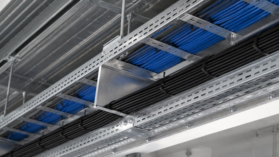
Access control and data cabling (Cat6, RS-485 instrumentation, 24 V DC control loops) is usually jacketed in gray or white and runs in dedicated conduit or a physically separated tray section. When that separation breaks down — during a renovation, typically — you end up with Class 2 cable and 480 V feeder sharing conduit. That’s a code violation and a genuine fire risk.
Industrial Plants
On a manufacturing floor, the standard practice in most plants I’ve seen is gray conduit for 24 V DC instrumentation and control, black or metallic conduit for 480 V and 600 V motor feeders. That convention is not universal and it’s not code-mandated everywhere, so verify it against the site’s electrical drawings before trusting it. Cable tray segregation — separate trays with physical barriers — is the more reliable indicator when it exists. Instrumentation cable running to a PLC I/O rack will also typically be shielded (you’ll see a drain wire or foil wrap under the jacket), which power feeders are not.
In industrial facilities, gray conduit always indicates low-voltage control wiring.False
Gray conduit is a common convention for LV control circuits in many plants, but it is not universally standardized by code. Always verify against site-specific electrical documentation before assuming voltage level.
Photovoltaic and Battery Storage Systems
This is the one area where visual identification can genuinely mislead you. PV string and combiner wiring physically resembles standard 600 V USE-2 or PV-rated cable — black jacket, similar diameter — but DC bus voltages in utility-scale or even commercial rooftop systems routinely reach 600–1,500 V DC. DC voltage is more dangerous than equivalent AC at the same nominal level because there’s no zero-crossing to interrupt an arc. Before touching any wire on a PV array or battery rack, test with a DC-capable meter. A standard multimeter set to AC range will read near zero on a live DC string. That’s not a safe reading; that’s the wrong test mode.
Outdoor and Underground Cables
Direct-burial 600 V URD (underground residential distribution) cable is typically black-jacketed, relatively small in diameter (roughly 1/2 to 3/4 inch for common residential sizes), and will have “600 V” and “Direct Burial” on the jacket. Medium-voltage distribution cable — 15 kV, 25 kV, 35 kV — is substantially thicker due to the insulation wall required, often 1 inch or more in diameter, and will carry a voltage class designation on the jacket. Orange warning tape or conduit signals direct-buried service below, but it doesn’t tell you the voltage. Always call for cable locating before any excavation, and treat any unearthed cable as energized until tested.
Quick-Reference Matrix
| Application | Typical Voltage | Cable Type | Visual Identifier | Test Method |
|---|---|---|---|---|
| Doorbell / transformer | 16–24 V AC | 18–22 AWG, thin or no jacket | Soft, small gauge, often unsheathed | Non-contact tester or multimeter (AC range) |
| Thermostat | 24 V AC/DC | 18 AWG multi-conductor, CL2 | “CL2” jacket print, multi-wire, thin | Multimeter AC range |
| Fire alarm (NFPA 72) | 24 V DC | Shielded or unshielded, red jacket | Red jacket, “FPLR” or “FPL” marking | Multimeter DC range |
| PLC/instrumentation | 24 V DC | Shielded multi-pair | Gray conduit, foil/drain shield visible | Multimeter DC range — verify polarity |
| PV string / battery bus | 100–1,500 V DC | USE-2 or PV-rated, black jacket | Resembles standard LV cable — no reliable visual | Multimeter DC range only; never assume de-energized |
| Direct-burial URD | 600 V AC | Black PE jacket, single conductor | “600 V Direct Burial” print, moderate diameter | Call locating service first; then multimeter |
| MV underground | 5–35 kV | Thick XLPE, large diameter | Voltage class on jacket, diameter noticeably larger | Do not test with standard DMM; use HV probes or call utility |
How Cable Construction and Cross-Section Reveal Voltage Class to a Trained Eye
Once you’ve read the jacket markings, the next layer of evidence is the cable’s physical construction itself. Cut a cable end cleanly or look at an exposed cross-section and you’re reading a fairly honest record of what voltage class the manufacturer designed it for. This takes some practice, but the logic is consistent across standards.
Insulation Thickness: The Most Direct Physical Indicator
IEC 60502-1 sets minimum insulation wall thicknesses for 0.6/1 kV cables, and the numbers are modest by design — roughly 0.7 mm for a 1.5 mm² conductor, scaling up to around 1.0 mm for a 50 mm² conductor. In practice, measure the insulation wall on an individual core with a caliper or even a careful visual estimate. If it’s somewhere in the 0.7–1.1 mm range, you’re almost certainly looking at a low-voltage cable built to that tier.
Medium-voltage cables change the picture immediately. A 3.6/6 kV cable starts at roughly 2.5 mm of insulation thickness on the core, and that figure climbs steeply — a 12/20 kV cable might carry 5.5 mm or more. When you see insulation that looks disproportionately thick relative to the conductor beneath it, that’s a real warning sign that you’re not dealing with anything in the LV class.
Semiconducting Screens: The Clearest Visual Giveaway
This is the detail that separates the trained eye from the untrained one. Low-voltage cables have a single extruded insulation layer on each conductor. That’s it — conductor, then insulation, then usually a filler or jacket. No mystery layers.
Medium-voltage cables, typically from 3.6/6 kV upward, add inner and outer semiconducting (semi-con) layers — one applied directly over the conductor before the main insulation, one applied over the insulation surface. Both are black, slightly softer than the main insulation, and visually distinct if you’re looking for them. Find black layers sandwiching the insulation on a core, and you can be confident you’re not in the LV range anymore. This isn’t optional for MV construction; it’s required by design to control electric field stress.
Metallic Screens and Armoring
Closely related: medium-voltage cables also carry a metallic screen — copper tape, copper wire, or aluminum foil — wrapped around each core or the assembled cable. LV cables may have armoring (steel wire, steel tape, or aluminum tape for mechanical protection), but a dedicated metallic screen around individual cores is an MV signature, not an LV one. Confusing armoring with screening is a common mistake on the plant floor, particularly with steel-tape-armored LV cables like the YJLV22 0.6/1 kV type — the armor is there for mechanical protection, not field control, and it sits outside the assembly rather than intimately around individual insulated cores.
A metallic screen around individual insulated cores always indicates a medium-voltage cableTrue
IEC 60502-1 requires metallic screens on MV cable cores for electric field control; LV cables under IEC 60502-1 do not require individual core screens, though the overall cable may have armor or a collective foil screen for EMI purposes in certain instrumentation cables.
Conductor Cross-Section as Circumstantial Evidence
Cross-section alone won’t definitively tell you the voltage class — large conductors exist at both LV and MV — but it narrows the field. Residential branch circuits in the LV range typically run 1.5–6 mm². LV sub-mains and distribution feeders cover roughly 10–240 mm². If you’re looking at something in the 300–630 mm² range inside a relatively thin-walled jacket with no semiconducting layers, you’re almost certainly looking at LV busbar cable or possibly flexible welding cable, not anything MV.
A standard Jinda YJV (XLPE insulation, PVC outer jacket, 0.6/1 kV) or NYY (PVC insulated and jacketed, 0.6/1 kV) in, say, 4×70 mm² has a lean, uncomplicated cross-section — each core shows conductor, a clean XLPE or PVC insulation wall of around 0.9 mm, and that’s the end of it. Compare that to a Jinda YJV22-8.7/15 kV medium-voltage cable of similar conductor size: you’ll immediately see the inner semi-con layer, the substantially thicker XLPE insulation, the outer semi-con, then copper wire screen, then bedding, then steel tape armor, then jacket. The physical bulk difference is obvious even before you reach for a caliper.
Stranding and Flexibility Class
Stranding class is less definitive for voltage identification, but it’s worth noting. Class 1 (solid conductor) and Class 2 (standard stranded) dominate fixed LV installations. Class 5 and Class 6 fine-stranded constructions indicate flexible or portable cables — power tools, portable equipment, trailing cables — and these are essentially always LV. That said, stranding class alone won’t confirm voltage rating, so treat it as supporting context rather than hard evidence. A highly flexible, finely stranded construction does make MV very unlikely, since MV flexible cables are a specialty product and rare in most facilities.
The practical takeaway: get a clean cross-section view whenever you can, and work through the checklist in order — insulation thickness, presence of semi-con layers, metallic core screens, then conductor size. Each layer of evidence either confirms LV or starts pointing toward something that needs very different handling.
Sourcing and Procuring Low-Voltage Cable: Specification Checks That Prevent Field Misidentification
Getting the right cable specified and delivered sounds straightforward. In practice, it’s where a surprising number of field misidentification problems actually originate — not on the installation floor, but months earlier, in a purchase order that was underspecified or a supplier who made a quiet substitution.
Writing a Complete Cable Specification
A cable specification that just says “4-core 6 mm² low-voltage power cable” is not a specification. It’s an invitation for the supplier to ship whatever comes closest in their warehouse.
A complete spec should state the rated voltage in Uo/U format — for most general power distribution work, that’s 0.6/1 kV. Uo is the conductor-to-ground voltage, U is the conductor-to-conductor voltage; both matter for insulation design. Alongside that, specify the insulation material (XLPE or PVC, and if PVC, whether it needs to be low-smoke zero-halogen for the installation environment), conductor material (copper or aluminum), and conductor class per IEC 60228 — Class 2 for fixed wiring, Class 5 for flexible. Then armoring type if required: SWA (steel wire armour) for direct burial or mechanical protection, STA (steel tape armour) for lighter applications, or unarmored if it’s running in conduit. Jacket material, the applicable standard (typically IEC 60502-1 for 0.6/1 kV cables), and any certification marks required for the country of installation — CE marking for Europe, SASO for Saudi Arabia, SONCAP for Nigeria, and so on.
Country-of-installation requirements deserve specific attention. Some markets accept IEC test reports from the factory; others require third-party witness testing from a recognized body like KEMA, DEKRA, or SGS before the cable clears customs. Get this confirmed with the local authority having jurisdiction before you cut a purchase order, not after the drums land at port.
Drum Labeling and Arrival Checks
IEC 60500 sets out what a drum end-tag should carry: cable type designation, rated voltage, drum number, length (with tolerance), and manufacturing date. On arrival, check every drum against the packing list. Specifically look at the rated voltage printed on the tag and on the cable jacket itself — they should match. A drum labeled “300/500 V” when you ordered “0.6/1 kV” is a 50% reduction in voltage rating, and the physical cable looks almost identical to the untrained eye. Same jacket diameter range, similar color, same conductor cross-section. The only reliable differentiator is the jacket printing and the test documentation.
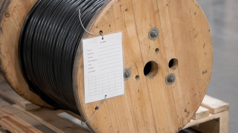
A 300/500 V cable physically resembles a 0.6/1 kV cable of the same cross-section but has insulation designed for roughly half the voltage stress, making it unsuitable and non-compliant when installed in a 0.6/1 kV system.True
IEC 60502-1 specifies insulation thickness and withstand requirements by voltage class; a 300/500 V cable (covered under IEC 60227 or similar) has thinner insulation designed for lower dielectric stress, and will not pass the 3.5 kV AC withstand test required for 0.6/1 kV cable.
Third-Party Test Reports
For a 0.6/1 kV cable, the factory test report should include conductor DC resistance per IEC 60228, insulation resistance after immersion, and a high-voltage withstand test — typically 3.5 kV AC applied for 5 minutes between conductors and between each conductor and the screen or armour. Insulation thickness measurements at multiple cross-sections should also be reported, confirming compliance with the minimums in IEC 60502-1. Request these per drum lot, not just per cable type. A type-approval certificate tells you the design was tested; a lot-specific report tells you what you actually received.
Substitution Risk Is Real
The 300/500 V substitution scenario happens more often than buyers expect, usually when a supplier is short on 0.6/1 kV stock and assumes the difference won’t be caught. Your protection is a specification that explicitly states “0.6/1 kV rated per IEC 60502-1, no substitution permitted,” combined with an incoming inspection that checks jacket printing against the purchase order before the drums move to the installation area.
Practical Procurement Details
Standard sizes in 0.6/1 kV XLPE or PVC power cable typically carry an MOQ in the range of 500–2,000 m per conductor cross-section, depending on the manufacturer’s minimum run. Lead times for catalog sizes run roughly 15–45 days; complex constructions — unusual armoring combinations, special jacket compounds, non-standard conductor configurations — can push that to 60 days or beyond. If your project requires custom jacket printing with circuit identification, voltage marking, or project-specific text, that can usually be accommodated at the extrusion stage for no significant cost premium, but it needs to be called out in the specification before production starts, not requested after.
Jinda supplies 0.6/1 kV and related LV cable with IEC factory test reports as standard, third-party certification through SGS, DEKRA, and KEMA available on request, and drum labeling in English for straightforward customs clearance and site receiving inspection. For international projects where the cable needs to clear multiple inspection points — factory, port, and site — consistent documentation in a single language eliminates one of the more tedious sources of delay.
Frequently Asked Questions About Identifying Low-Voltage Wire
Can I identify a low-voltage wire just by its color without testing it?
Color is a useful first filter, not a verdict. The problem is that color codes differ significantly by region — IEC installations use brown for live and blue for neutral, while NEC installations use black and white — and any installation older than 20 or 30 years may have been wired before current standards took hold, rewired by someone working from a different country’s habit, or simply done wrong. On older industrial sites especially, you will occasionally find a “ground” conductor that is actually carrying load because someone ran out of the right wire a decade ago. Use color to narrow your hypothesis, then confirm with jacket markings and a live instrument test before you touch anything. Color alone is never conclusive.
Is 12 V DC wire considered low voltage?
Yes, though technically it sits in an even safer subcategory. IEC 60038 carves out extra-low voltage (ELV) as anything at or below 50 V AC or 120 V DC. At 12 V DC — common in automotive wiring, LED lighting, and control circuits — you are well inside ELV territory, which is itself a subset of the broader low-voltage class. Under dry conditions, 12 V DC poses negligible electrocution risk to a healthy adult. That said, high-current 12 V systems (think large battery banks or automotive starter circuits) can deliver enough fault current to cause serious arc burns or fires if shorted, so “safe voltage” does not mean “treat it carelessly.”
What is the difference between a low-voltage cable and a low-voltage wire?
Strictly speaking, a wire is a single conductor — insulated or bare — while a cable is two or more insulated conductors assembled under a common outer jacket. In everyday trade conversation these terms get used interchangeably, and most buyers and installers say “wire” when they mean cable. From a voltage classification standpoint, it doesn’t matter: the IEC and NEC ratings apply to the assembly regardless of what you call it. Where the distinction does matter is in a specification document or a purchase order — writing “low-voltage wire” when you need a multi-core armoured cable will cause your procurement team real headaches.
How do I test a buried cable to determine if it is low voltage without digging it up?
Don’t assume anything about a buried cable. The practical approach: use a cable locator (a pipe-and-cable detector, the kind that works on signal induction) to trace the route and confirm there’s only one cable where you think there is. Then find a termination point — a junction box, a distribution panel, a meter enclosure — and test there with a non-contact voltage tester or a properly rated DMM. If you can get access to the cable’s documentation or as-built drawings, check the drum label or installation records. Buried cables have a habit of being re-energized after maintenance windows without notification to everyone on site.
Does low-voltage cable require conduit, or can it run exposed?
Depends heavily on the application and your local code, and this is an area where people get tripped up. NEC Class 2 wiring — typically 30 V or below, covering things like doorbell circuits, thermostat wiring, and some control wiring — has relaxed installation requirements and can often run exposed in concealed spaces. But once you’re in the 120–1,000 V range that forms the bulk of LV power distribution, NEC and IEC 60364 both impose specific wiring methods: conduit, cable tray, direct burial with appropriate armoring, and so on. “Low voltage” does not mean “no rules.”
How can I tell if a cable is low voltage versus medium voltage in a mixed cable tray?
Physical size is the fastest indicator — MV cables are noticeably larger in diameter because they need substantially thicker insulation. At terminations, look for a metallic screen or shielding layer; LV power cables rarely have this, while MV cables almost always do. The voltage rating printed on the jacket is definitive if you can read it. And look at how the tray is organized: most electrical codes require physical separation between MV and LV circuits, either by a physical barrier within the tray or separate trays entirely. If everything is jumbled together with no separation, that itself is a code violation worth flagging before you do anything else.
What certifications should a low-voltage cable from China have for use in my country?
This depends entirely on the destination market, and getting it wrong means the cable may fail customs inspection or be rejected by a local authority having jurisdiction. For the EU, you need CE marking and conformance to the Construction Products Regulation (EU 305/2011), with the cable typically tested to IEC 60227 or IEC 60502 depending on type. For the US market, UL listing is the standard requirement. Australia requires C-Tick/SAA marking. The Middle East, depending on the specific country, commonly requires SASO (Saudi Arabia) or ESMA (UAE) certification.
Jinda holds multiple international certifications including CE, IEC, UL, and can provide country-specific documentation for export projects.True
Jinda is an established cable manufacturer with documented international certifications serving customers in more than 50 countries; country-specific certification documentation is a standard requirement for export cable projects and is part of Jinda's stated offering.
Always request the actual test reports and certification documentation — not just a statement on a product datasheet — before finalizing a large procurement. Any serious manufacturer will have these on file.
Summary Decision Tree: A Step-by-Step Protocol for Confirming Low-Voltage Status on Any Wire
Every step in this article — visual inspection, marking literacy, instrument testing, construction analysis — feeds into one practical question: is this wire safe to work on at the LV level, or isn’t it? This protocol consolidates those methods into a sequence you can print, laminate, and clip to a tool bag. Follow it in order. Skipping steps is where injuries happen.

Step 1 — Gather Documentation First
Before you get within arm’s reach of any conductor, pull the panel schedule, the as-built drawings, and the cable schedule. This takes five minutes and it has saved more than a few engineers from testing what turned out to be 6.6 kV in a trunking they assumed was LV controls. If documentation clearly identifies the circuit as low voltage, you still put on appropriate PPE — documentation confirms intent, not necessarily current field state. If documentation is absent, illegible, or conflicts with what you’re looking at physically, treat the wire as unknown voltage and proceed accordingly through the remaining steps without assumptions.
Step 2 — Visual Inspection
Examine the jacket print carefully. A properly manufactured LV cable will carry a rated voltage designation — typically 0.6/1 kV under IEC standards — printed at regular intervals along the outer sheath. Confirm the color coding matches the regional standard for your site (NEC or IEC; they differ enough to cause real confusion on international projects). Then look at the cable’s physical construction. A metallic screen, an armored bedding over a thick inner sheath, or visibly heavy insulation walls suggest you may be looking at MV or HV cable. LV cables are not always thin, but they rarely have the layered cross-section of a medium-voltage design. If anything looks heavier than the circuit description suggests, stop and treat it as unknown.
Step 3 — Non-Contact Voltage Test
Use a calibrated non-contact voltage tester (NCVT) — check its calibration date; an out-of-date instrument is not a safety tool, it’s a false confidence generator. If the NCVT reads voltage present, do not touch the conductor under any circumstances. If it reads absent, resist the temptation to assume the circuit is dead. Shielded cables actively suppress the electric field an NCVT depends on, and DC circuits won’t trigger it at all. Absence of an NCVT reading is not clearance to proceed.
Non-contact voltage testers will not reliably detect voltage in shielded or screened cables, or in DC circuits.True
NCVT tools detect the capacitively coupled electric field around an energized conductor. A metallic screen tied to ground diverts that field, preventing the instrument from sensing voltage on the inner conductor. DC circuits produce no alternating field and are invisible to NCVT detection entirely.
Step 4 — Instrument Measurement
With CAT III or CAT IV rated PPE in place, use a CAT III or CAT IV digital multimeter to measure both AC and DC voltage. Record both readings. Compare the AC reading against the rated voltage printed on the jacket. A reading within roughly ±10% of rated voltage confirms an operational LV circuit under normal load conditions. A reading significantly outside that range — or any reading above 1,000 V AC or 1,500 V DC — means you stop immediately and escalate.
Step 5 — Cross-Check with Current Measurement
Clip a clamp meter around one conductor and check the load current against what you’d reasonably expect for the conductor cross-section. A 2.5 mm² conductor carrying 80 A is a problem, not an anomaly to note and move on from. Anomalously high current on a small conductor can indicate mis-labeling, a tapped-in feed from a higher-voltage source, or a fault condition — any of these warrants investigation before anyone proceeds.
Step 6 — Document and Label
Once all five steps confirm LV status, apply a permanent voltage-class label at both cable ends and at every accessible junction. Update the panel schedule and cable schedule on the spot, not later. “Later” means the next person on site works from the same undocumented starting point you just spent time resolving.
When to Stop and Call a Specialist
Any reading above 1,000 V AC or 1,500 V DC. Any insulation that looks cracked, carbonized, swollen, or abraded. Any reading inconsistent with what the documentation says. All three of these call for a licensed high-voltage electrician or protection engineer — not a judgment call by whoever happens to be on site with a multimeter.
How Jinda’s Factory Identification System Reduces Field Ambiguity
One thing that quietly shortens this whole process is receiving cable that’s already unambiguously marked. Jinda prints IEC-standard voltage designation, conductor size, and standard references at consistent intervals along every meter of jacket — no hunting for a faded stamp near the drum end. Drum-end tags carry the same information in full, and QR-code-linked test certificates tie each drum to factory test records you can pull on a phone before the cable ever leaves the reel. In practice, that means when Step 2 above says “check the jacket print,” there’s something legible to check. It’s a small thing that makes a real difference when you’re moving fast on a large installation.