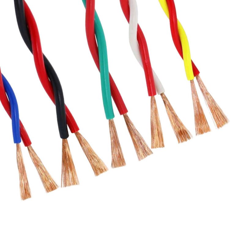
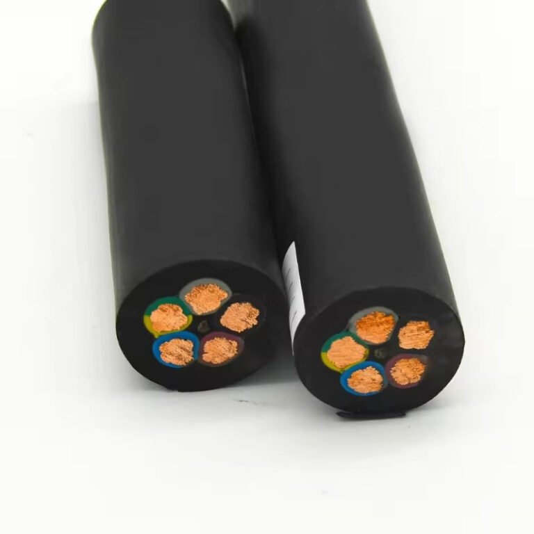
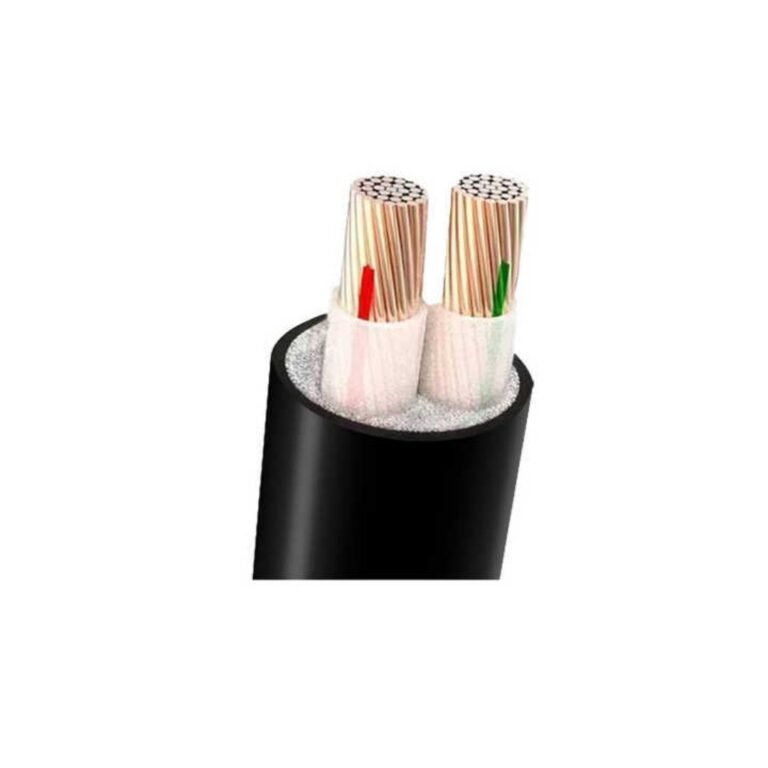
A shallow 240V trench can look harmless until a landscape crew, frost movement, or a compacted driveway exposes the weak point. Then the plant is dealing with nuisance trips, water-damaged insulation, failed inspection, or an unplanned shutdown. The right answer starts with the wiring method, protection system, soil conditions, and the code authority that will sign off the work.
For most 240V underground runs, burial depth is not set by voltage alone: it depends on cable type, conduit, circuit protection, soil, and local electrical code. As a practical starting point, expect roughly 18–24 inches for many conduit or direct-buried installations, then verify before trenching.
The confusing part is that two 240V circuits can have different legal burial depths on the same site. A direct-buried armored cable, a PVC conduit run, a rigid metal conduit crossing, and a protected low-voltage control circuit are not treated the same in practice, and procurement needs to specify the cable construction before the trench is priced.
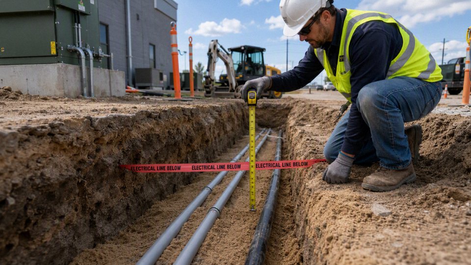
Code factors controlling depth
Legal burial depth is controlled first by the installation rule set, then by the wiring method and site exposure. A 240V circuit under a lawn, in a PVC raceway, serving a gate motor is not the same risk as a 240V feeder crossing a truck yard, even if the voltage printed on the drawings looks identical.
A 240V cable always has one legal burial depth.False
Burial cover is normally determined by the applicable code, wiring method, mechanical protection, circuit type, location, and inspection authority requirements. Voltage matters, but it is rarely the only control variable.
The first control point is the rule book that will be enforced
Start with the standard that the inspector, utility, insurer, or site owner will actually use. I have seen perfectly sensible underground cable designs rejected because the contractor designed to a national code table while the project specification added a deeper cover requirement for all traffic areas. That is not an engineering debate at the trench; it is a procurement and compliance failure.
The governing documents usually stack in this order:
- National electrical code or wiring regulation
- Examples include NEC in the United States, CEC in Canada, BS 7671 in the UK, AS/NZS 3000 in Australia and New Zealand, IEC-based national rules in many markets, and country-specific utility or ministry standards elsewhere.
- These documents define wiring methods, permitted cable types, protection requirements, and minimum cover rules.
- Local amendments
- Cities, counties, provinces, industrial parks, and port authorities may add requirements for road crossings, public right-of-way work, corrosive soils, or inspection access.
- Local amendments often matter more than the national table on small jobs because they are what the permit office enforces.
- Utility interconnection and service rules
- A service lateral, metering connection, or grid-tied supply may fall partly under utility requirements, not only the building electrical code.
- Utilities may specify duct color, warning tape, tracer wire, minimum separation from gas or water, bend radius, pulling points, and inspection before backfill.
- Site owner or project specifications
- Factories, mines, logistics yards, airports, campuses, and food plants often maintain internal standards for underground services.
- A plant standard may require concrete encasement, spare ducts, red marker tape, detectable tape, or deeper cover in forklift and trailer areas.
- Authority having jurisdiction interpretation
- The written rule still needs interpretation in the field. Inspectors may classify a gravel access lane as a driveway, a maintenance strip as a vehicle area, or a covered outdoor process skid as an industrial equipment zone.
- Get that classification settled before the trench is open. Recutting a trench because of an interpretation difference is expensive and it annoys everyone involved.
The engineering mistake is treating the cable purchase as separate from the installation rule. Cable type, armor, sheath, conduit, trench depth, bedding, marker tape, and inspection records are one compliance package.
Direct burial versus conduit changes both depth and maintenance
Direct-buried cable and cable installed in conduit or duct are not interchangeable installation methods. Direct burial relies on the cable construction itself for moisture resistance, soil contact durability, and mechanical survival. Conduit or duct shifts part of that duty to the raceway, but introduces pulling friction, bend radius limits, water collection, duct joint quality, and future cable replacement questions.
A practical comparison looks like this:
| Installation method | What controls the depth decision | Procurement and maintenance consequence |
|---|---|---|
| Direct-buried cable | Cable listing or approval for direct burial, soil exposure, mechanical damage risk, code cover table | Fewer materials and faster trench work, but repairs usually require excavation at the fault location |
| PVC or polymer conduit | Raceways provide mechanical separation from soil and some damage protection; cover still depends on code and exposure | Easier future replacement if conduit is sized and installed well; poor joints, crushed duct, or water traps can defeat the benefit |
| Rigid metal conduit or equivalent heavy protection | Stronger mechanical protection may permit different cover under some codes and locations | Higher material and labor cost, corrosion protection becomes a serious design issue |
| Duct bank or concrete encasement | Used where mechanical loading, future circuits, or owner standards justify it | Good protection and layout control, but heat dissipation and installation cost must be checked |
The mechanism is simple but often ignored: the raceway changes the failure mode. In direct burial, the cable sheath is the first line of defense against stones, wet soil, and small excavation damage. In conduit, the cable is protected from direct soil contact, but it may run hotter if the raceway group is crowded, poorly dissipates heat, or sits in dry backfill with high thermal resistivity. The better mechanical solution can be the worse thermal solution if nobody checks ampacity.
The trade-off flips depending on the job. For a short outdoor branch circuit to fixed equipment in a controlled landscape area, conduit may be selected mainly for replacement convenience and inspector comfort. For a long feeder to an outbuilding or pump station, direct-buried armored cable may reduce pulling risk and duct installation time, provided the cable is certified for the environment and the required cover can be achieved. In a truck yard, road crossing, or plant expansion zone, I would usually rather see robust duct or encasement than trust a warning tape to save a cable from the next excavator bucket.
Circuit duty changes the risk profile
Burial-depth tables are usually organized around wiring method and location, but circuit duty still matters because it affects consequences of failure, conductor size, fault energy, and how likely the circuit is to be modified later.
Common 240V underground circuits include:
- Residential or commercial branch circuits
- Outdoor receptacles, small equipment, lighting panels, heat trace, or compact machinery.
- Usually lower current, but often installed by smaller contractors where trench marking and as-built records are weak.
- Feeders
- Supplies to subpanels, outbuildings, workshops, barns, pump houses, or process skids.
- Larger conductors and higher available fault current make cable protection, terminations, and overcurrent coordination more consequential.
- Service laterals
- Utility-side or customer-side service conductors, depending on jurisdiction.
- These may be governed by utility rules as much as the electrical installation code.
- Outdoor equipment supplies
- HVAC units, compressors, packaged process equipment, irrigation controllers, gate operators, signs, and wash-down equipment.
- Vibration, wet locations, and maintenance traffic around the equipment can be more damaging than the buried run itself.
- Lighting circuits
- Landscape lighting, site lighting, security lighting, bollards, and pole bases.
- Shallow installations are tempting here because loads are modest, but pole bases and landscaping crews create frequent mechanical damage points.
- Irrigation pump and water system supplies
- Wet soil, seasonal movement, rodents, and accidental excavation are common.
- Cable and gland selection must match wet-location and submersible or pump-control requirements where applicable.
- Electric gates and access-control circuits
- Often share trenches with signal wiring, controls, loops, or communication cable.
- Separation, interference, and future troubleshooting access matter; low-voltage control cable does not automatically make the adjacent power cable lower risk.
- Outbuilding feeders
- Garages, farm buildings, sheds, detached workshops.
- Grounding, bonding, disconnecting means, and physical route protection must be coordinated with burial requirements.
- EV charging feeders
- High continuous load, often near driveways or parking areas.
- Ampacity, heat dissipation, voltage drop, and vehicle loading over the route all deserve more attention than on a light-duty branch circuit.
- Industrial auxiliary power
- Power for conveyors, remote panels, dust collectors, pumps, tank farms, weighbridges, and yard equipment.
- The cable route may pass through areas that change use over time. Today’s pedestrian strip becomes next year’s material staging lane; I have watched that happen more than once.
Voltage class, current rating, conductor size, available fault level, and protective device selection influence the seriousness of an installation even when the minimum cover number comes from a table. A 240V feeder protected by a large breaker can release enough fault energy to damage equipment and create an arc event at a faulted termination. A small 240V lighting branch circuit is not harmless, but its repair and protection strategy may be different.
The overcurrent device also affects cable survivability. If the protective device is oversized, incorrectly coordinated, or has high let-through energy during a fault, the cable may suffer more damage before clearing. That does not normally let you reduce burial depth, but it does influence whether you choose armor, metallic conduit, warning systems, or a more conservative route.
Mechanical exposure is where neat drawings meet machinery
The same cable depth that looks acceptable in a garden bed may be poor practice under a delivery lane. Mechanical exposure is not just “traffic or no traffic.” It includes the likelihood of future digging, surface loading, settlement, and abuse by people who do not know the cable exists.
Typical exposure categories should be classified before procurement:
- Garden beds and landscaped strips
- High risk from spades, edging tools, irrigation repair, and root work.
- Marker tape and accurate route records help, but shallow private landscaping work is still a common damage source.
- Lawns and pedestrian areas
- Lower surface load, but aerators, fence posts, sign posts, and drainage work can reach cables if cover is marginal.
- Parking lots and driveways
- Wheel loads, subbase compaction, resurfacing, and drainage repairs increase risk.
- Duct selection and cover should consider future pavement maintenance, not just today’s installation.
- Road crossings
- Usually require more robust protection, controlled bedding, and sometimes sleeves or duct banks.
- Open-cut work may be restricted; bored installations bring their own depth and locating tolerances.
- Warehouses and industrial yards
- Forklifts, reach stackers, pallet racking anchors, temporary buildings, and slab saw-cutting can all affect underground services.
- In plants, assume the yard layout will be changed by someone with a deadline and a rented machine.
- Farms and rural properties
- Plows, augers, fence posts, drainage tile work, livestock damage near risers, and seasonal moisture changes matter.
- Direct-buried cable must be selected with rodents, wet soil, and mechanical impact in mind.
- Construction yards and temporary works
- The route may be crossed by cranes, telehandlers, trenchers, and temporary roads.
- Temporary does not mean casual; temporary power often sees the worst abuse.
- Excavation-prone corridors
- Areas near water lines, gas lines, drainage, fiber, process piping, or future expansion zones deserve stronger marking and separation.
- Good as-built drawings are not paperwork decoration. They prevent outages years later.
Soil and environment can override the comfortable choice
Soil conditions control both cable durability and thermal performance. Clay holds water, sand drains quickly, rocky soil damages sheath during backfill, and chemically contaminated soil can attack metal armor or sheath materials. If the cable route crosses different soil zones, design to the worst section or specify different protection methods by segment.
Key environmental controls include:
- Soil type and compaction
- Loose fill settles and can create voids around conduit.
- Over-compacted backfill can crush weak duct or damage cable if bedding is poor.
- Drainage and water table
- Underground conduits often contain water eventually, even when installed neatly. Treat “watertight forever” as wishful thinking unless the system is specifically designed and tested for it.
- Wet-location rated conductors, sealed entries, and proper duct slopes reduce trouble.
- Corrosivity
- Salts, industrial runoff, fertilizers, acidic soil, and coastal environments affect armor, metallic conduit, glands, and grounding components.
- Corrosion protection must be compatible with the cable and earthing system.
- Rock content
- Sharp stones are brutal on direct-buried sheath.
- Screened sand or specified bedding may be cheaper than a fault repair under finished paving.
- Frost movement
- Freeze-thaw cycles can move soil, stress risers, and damage shallow transitions.
- The straight buried run may survive while the stub-up into equipment fails.
- Chemical contamination
- Fuel, solvents, process chemicals, manure, wastewater, and cleaning agents may require specific sheath compounds or secondary containment decisions.
- Do not assume a standard PVC sheath is suitable for every industrial soil.
- Thermal resistivity
- Dry, loose, or poorly selected backfill can trap heat around loaded conductors.
- This matters on EV feeders, large outbuilding feeders, pump supplies, and industrial circuits with long duty cycles.
- Bedding material
- Bedding protects the cable or duct and supports heat transfer.
- The cheapest backfill from the spoil pile is not always acceptable; lumps of concrete, brick, and sharp aggregate have no place against a direct-buried cable.
Deeper is not automatically safer
Excessive depth can create new problems. A deeper cable is harder to locate, harder to repair, more expensive to excavate, and more likely to conflict with drainage, gas, water, sewer, communications, foundations, or future civil work. It can also worsen thermal conditions if the cable sits in deep, dry, insulating soil or in a congested duct bank without ampacity correction.
The practical limit of “go deeper to be safe” is reached when depth starts reducing maintainability or thermal reliability. A failed shallow cable in a landscaped strip is annoying. A failed deeply buried feeder under pavement, below other services, with no spare duct and no accurate drawing can shut down a section of a facility while everyone argues over who owns the excavation permit.
For buyers, the specification should not stop at “240V underground cable.” It should state the applicable code, cable construction, conduit or direct-burial method, exposure category, soil and bedding assumptions, marking tape requirements, inspection hold points, and documentation required with the cable shipment. The minimum legal cover is only one line in the design; the durable installation is the combination of cable, route, protection, environment, and records.
Common burial-depth ranges
Common 240V underground installations often fall around 24 in. of cover for direct-buried cable, 18 in. for cable in approved nonmetallic conduit, and shallower depths in rigid metal or intermediate metal conduit where the local code allows it. Treat those as planning ranges, not permission to dig: the authority having jurisdiction, project specification, utility rules, and inspection requirement decide the actual minimum cover.
| Installation method | Typical cover range often seen in code-based work | Common use case | Key limitations | Verification notes |
|---|---|---|---|---|
| Direct-buried underground feeder or direct-burial-rated cable | Roughly 24 in. / 600 mm cover is a common benchmark | Residential feeders to garages, outbuildings, pumps, gate equipment, small site loads | Cable must be listed/rated for direct burial; vulnerable to future digging, stones, poor bedding, and settlement; splice and termination rules are strict | Confirm cable type, burial rating, GFCI requirements if applicable, marking tape, bedding, and inspection before backfill |
| Cable in approved PVC or other nonmetallic conduit | Roughly 18 in. / 450 mm cover is common in many residential-style installations | House-to-shed feeders, landscape equipment, light commercial site circuits, protected branch circuits | May not apply under driveways, parking areas, public roads, farm lanes, or industrial traffic routes; conduit schedule and burial rating matter | Verify conduit material, wall thickness, cover under traffic, expansion fittings, bends, pulling fill, and local inspection details |
| Cable in rigid metal conduit or intermediate metal conduit | Often allowed at shallower cover in some jurisdictions, sometimes around 6–12 in. / 150–300 mm depending on circuit and location | Where mechanical damage risk is high, shallow routing is unavoidable, or the run transitions up walls, poles, and equipment pads | Higher material and labor cost; corrosion protection and bonding continuity must be handled correctly; not all shallow installations qualify | Confirm raceway type, corrosion environment, bonding, burial fittings, cover table used by the inspector, and transition details |
| Low-voltage landscape or protected branch-circuit exceptions | Can be shallower in specific cases | Low-voltage lighting, control circuits, limited residential branch-circuit cases with required protection | These exceptions usually do not apply to standard 240V feeders serving machinery, HVAC, pumps, EV chargers, or subpanels | Verify voltage class, overcurrent protection, GFCI/protective device requirements, cable listing, and whether the exception is recognized locally |
| Utility-style primary or service laterals | Often deeper and controlled by utility standard, not just building wiring code | Service entrances, transformer-to-building runs, multi-building sites, meter banks | Utility owner may require specific duct banks, warning tape, sand bedding, separation, mandrels, and as-built records | Get the utility construction standard before trenching; do not assume building-code cover tables control the work |
The reason 24 in. is so common for direct burial is simple: without a raceway, the soil cover is doing much of the mechanical protection. It creates separation from gardening tools, shallow grading, small equipment, freeze-thaw disturbance, and the normal abuse that comes later when someone forgets where the feeder was installed. Direct-burial-rated cable is built for wet soil exposure, but that does not make it immune to a skid-steer tooth, a sharp chunk of crushed concrete, or a fence-post auger.
That 24 in. number also assumes the cable itself is suitable. A standard indoor cable pulled straight into a trench is not made acceptable by burying it deeper. For procurement, the buyer should specify the installation environment clearly: conductor material and size, insulation voltage rating, direct-burial or wet-location rating, armor if required, outer sheath material, and the documentation needed for the destination market. On export or multi-site projects, I would rather see the buyer over-describe the installation than rely on a vague line such as “240V underground cable.” That wording is how purchasing gets a cheap cable that the field team cannot legally install.
For nonmetallic conduit, the commonly cited 18 in. cover benchmark comes from the raceway adding a defined layer of protection and providing a replaceable path for conductors. PVC also makes future cable changes less painful, provided the bends were not overdone and the conduit was not crushed during backfill. In practice, conduit runs fail less from the straight sections and more from careless elbows, poor solvent joints, no expansion allowance at building entries, and people backfilling with broken block because “it was already there.”
The 18 in. planning number becomes shaky under vehicle loading. A private lawn crossing is not the same as a driveway apron, a loading dock approach, or a plant road used by forklifts with solid tires. Soil compaction, rutting, surface maintenance, and future saw-cut work all change the risk. Some inspectors will require greater cover, a different conduit schedule, concrete encasement, or a utility-style duct detail in these areas. The preferred choice flips when traffic and future excavation risk dominate: PVC is economical and corrosion-resistant for many runs, but rigid metallic raceway or a deeper duct bank can be cheaper over the life of the site if it avoids shutdowns and repairs.
Rigid metal conduit and intermediate metal conduit earn their place where physical protection matters. Steel raceway resists shovel strikes, rodent damage, and shallow impact better than PVC, so some codes permit less cover in defined cases. That does not make it a universal shortcut. Buried metallic raceway brings its own maintenance questions:
- Is the soil corrosive, saline, chemically contaminated, or regularly wet?
- Are factory elbows and field threads protected after cutting?
- Is bonding continuous across couplings, expansion sections, and equipment entries?
- Are dissimilar metals present near grounding grids, galvanized structures, or stainless hardware?
- Will the installation be inspected before corrosion tape, concrete, or backfill hides the details?
Shallow cover is only defensible when the wiring method, location, circuit type, and local rule all support it. I have seen projects lose more time arguing over a 6 in. trench saving than they would have spent digging it correctly the first time, especially when the inspector arrives after the trench walls have sloughed in overnight.
Low-voltage and protected-circuit exceptions deserve careful handling because they are easy to misapply. Landscape lighting, communications, controls, and some protected residential branch circuits may qualify for reduced cover under specific rules. A 240V feeder to a subpanel, irrigation pump, compressor, heat pump, kiln, welder outlet, or EV charger should not be treated as “low voltage” just because the number is lower than medium-voltage distribution. In ordinary building electrical language, 120/240V is still a power circuit with shock, arc, and load-current consequences.
Residential, commercial, industrial, and utility-style installations differ less by the voltage label and more by exposure and accountability. A residential backyard feeder may be reviewed against a relatively simple trench detail, with inspection before backfill and warning tape above the cable or conduit. A commercial site adds parking lots, signage bases, irrigation contractors, snow-removal stakes, and future tenant improvements. Industrial sites are less forgiving again: underground cables may pass near process drains, chemical areas, grounding grids, steam lines, compressed-air headers, crane rails, or heavy foundations. Many plant standards deliberately exceed minimum code because the cost of one excavator hit can include lost production, product scrap, safety exposure, and a weekend callout crew.
Utility-style work is another category. Once the run involves service laterals, pad-mounted transformers, primary distribution, or utility-owned metering arrangements, the utility standard may control trench depth, duct type, red concrete, pull boxes, sweeps, mandrel testing, separation from gas and water, and as-built GPS records. The plant electrician may be qualified, and the cable may be perfectly good, but the utility can still reject the installation if its civil detail was not followed.

Several trench terms get mixed together on purchase orders and site sketches, and the confusion causes real rework:
- Burial depth or cover means the distance from finished grade down to the top of the cable, conduit, or raceway. This is the number most code tables are talking about.
- Trench depth is deeper than cover because it includes the cable or conduit outside diameter plus bedding below it.
- Bedding thickness is the selected material placed under and sometimes around the cable or conduit to avoid point loading from rocks, debris, or hard clay lumps.
- Warning tape position is usually above the cable or conduit, not directly on it. It is meant to be found by a shovel or machine before the electrical system is hit.
- Conduit spacing matters when multiple conduits are installed. It affects heat dissipation, pulling access, concrete encasement quality, and future identification.
- Final backfill height refers to the restored grade after compaction and settlement. Measuring cover from a loose spoil pile is a bad habit; the inspector cares about finished grade.
The mechanism behind these details is not academic. Cable ampacity depends partly on heat leaving the conductor through insulation, sheath, conduit, bedding, and soil. A single direct-buried cable in moist native soil sheds heat differently from six loaded conduits packed tightly in dry sand under asphalt. Depth affects mechanical protection, but deeper is not always electrically better if the installation creates poor heat dissipation or makes future repair nearly impossible. That is why engineered industrial feeders may require ampacity calculations, soil thermal data, spacing rules, or derating rather than just a deeper trench.
A standard 240V underground feeder always needs exactly 24 inches of burial depth.False
Twenty-four inches of cover is a common benchmark for many direct-buried installations, but legal cover depends on the wiring method, circuit protection, location, traffic exposure, cable listing, and the authority having jurisdiction.
For a practical drawing or jobsite note, avoid writing only “bury 240V cable 18 inches.” A better trench note identifies the wiring method and inspection basis:
- Circuit voltage, phase, and load served.
- Cable type, conductor material, conductor size, insulation rating, and wet-location or direct-burial listing.
- Raceway type, size, schedule, and fittings where conduit is used.
- Required cover from finished grade, with separate details for lawn, driveway, road, slab edge, and equipment-pad crossings.
- Bedding material and minimum bedding thickness.
- Warning tape color, wording, and placement above the cable or conduit.
- Separation from water, gas, drainage, communications, and other power circuits.
- Pull boxes, sweeps, expansion fittings, and spare conduits if needed.
- Inspection hold point before backfill.
- As-built record requirement, especially for commercial and industrial sites.
The usual cover ranges are useful for budgeting and early layout, but they stop being reliable once traffic loading, utility ownership, unusual soil, hazardous areas, high fault current, or site-specific engineering standards enter the job. At that point, the trench detail needs to be checked against the current local code, the inspector’s interpretation, the cable supplier’s documentation, and the project specification before excavation starts.
Cable type and protection
Cable selection is not just a purchasing line item; it changes the whole burial method, installation risk, and long-term failure mode. For a 240V underground circuit, the practical choice is usually between a cable designed to live directly in soil and a standard wet-location cable protected by conduit or duct. The better option depends on soil aggressiveness, expected digging exposure, pull length, future replacement needs, and what the local inspector will accept.
Main underground wiring options
The cable-and-protection system should be selected before trench depth is finalized, because codes often assign different cover requirements to different wiring methods. In practice, I treat the raceway or armor as part of the cable system, not as an accessory added later to rescue a weak specification.
| Underground option | Where it fits well | Main advantages | Watch points |
|---|---|---|---|
| Direct-burial-rated cable | Short to medium runs, farms, site lighting, small equipment feeds, residential or light industrial branch circuits where approved | Fewer parts, faster trench installation, no full-length conduit pulling | Must be rated for direct burial and wet locations; difficult to replace without excavation |
| Armored underground cable | Industrial yards, pump stations, perimeter power, areas with moderate mechanical risk | Better crush, impact, and rodent resistance than unarmored cable | Armor bonding, corrosion protection, bending radius, and termination glands matter |
| Cable in PVC conduit | Common for building feeds, equipment pads, outdoor panels, and future serviceability | Corrosion-resistant, economical, easier cable replacement than direct burial | Expansion, joint quality, pulling friction, and riser protection need attention |
| Cable in HDPE duct | Long site runs, directional drilling, utility-style installations, large project duct routes | Long continuous lengths, flexible, good for plowed or bored routes | Duct ovality, pulling tension, locator wire, and transition fittings must be specified |
| Cable in rigid metal conduit | Risers, exposed transitions, pole bases, building entries, traffic-exposed areas | High mechanical protection and good physical security | Corrosion risk underground; bonding continuity and coating damage must be controlled |
| Cable in a duct bank | Multi-circuit industrial plants, campuses, substations, future expansion corridors | Organized routing, spare ducts, inspectable entry points, better project control | Heat dissipation, derating, concrete encasement details, and pulling access dominate the design |
Direct burial looks simple on a drawing, but it is unforgiving. A sharp stone under backfill, a careless trench compactor, or a later fence-post auger can become the weak point. Conduit systems cost more in fittings, sweeps, labor, and pulling equipment, but they let maintenance recover from a damaged cable without reopening the whole route. The choice flips when the run is short, stable, and unlikely to change; then direct burial can be the most honest solution if the cable is correctly rated.
Underground cable systems should normally be treated as wet-location installations, even when the conduit or trench is expected to drain.True
Soil moisture, condensation, groundwater movement, and water entry at boxes or conduit ends make below-grade cable exposure fundamentally different from dry indoor wiring. The exact rating language must be verified against the applicable electrical code and cable standard.
Insulation, sheath, and environmental resistance
The insulation system carries the electrical stress; the sheath and armor survive the site. Confusing those two functions is a common procurement mistake. A cable can have good conductor insulation and still fail early because the outer jacket is not suitable for wet soil, sunlight at risers, hydrocarbons near equipment, or abrasion during pulling.
For underground 240V power circuits, the specification should address these exposure categories:
- Wet-location performance: Insulation and jacket materials must be suitable for continuous moisture exposure, not just occasional dampness. Water can migrate along conductor interstices, under shields, and through damaged jackets.
- Long-term dielectric performance: XLPE insulation is widely used in industrial power cable because it handles heat and electrical stress well. For low-voltage 240V circuits, dielectric stress is modest compared with medium voltage, but insulation aging still comes from heat, moisture, overload history, and installation damage.
- UV exposure at risers: The few feet where cable leaves the ground are often the harshest part of the installation. Sunlight, weed trimmers, vehicle splash, and maintenance traffic attack the jacket before the buried section shows any trouble.
- Abrasion resistance: Pulling through sweeps, duct mouths, or rough trench bottoms can shave a jacket. Good installers use rollers, pulling lubricant where allowed, and proper end caps; poor installers rely on muscle and luck.
- Chemical and oil resistance: Near generators, compressors, fueling areas, wastewater plants, or chemical storage, soil contamination can soften or crack some sheath compounds. PVC, PE, LSZH, and specialty jackets behave differently, so “underground rated” is not the same as “chemical resistant.”
- Rodent resistance: Armor, harder jackets, duct protection, or route selection may be needed where rodents are a known problem. Rodent damage is rarely neat; it often creates intermittent insulation faults that waste days of troubleshooting.
- Flame and smoke requirements: LSZH sheath may be required where underground cable enters tunnels, occupied buildings, transit spaces, or enclosed industrial galleries. It is not automatically better for every buried run; it is chosen because the fire environment demands it.
XLPE insulation with a PVC sheath is a common industrial construction, but it is not universal. LSZH sheaths, polyethylene jackets, water-blocking tapes, and metallic screens may be required depending on the standard, installation environment, and project owner specification. Water-blocking layers are especially useful where longitudinal water migration would turn one jacket nick into a long repair zone.
Conductor material and circuit configuration
Copper and aluminum can both work underground, but they do not buy the same installation experience. Copper gives higher conductivity in a smaller conductor size, better termination tolerance, and less sensitivity to handling mistakes. Aluminum usually lowers material cost and weight, especially on longer feeders, but it needs larger cross-sectional area, compatible lugs, oxide control, correct torque, and maintenance discipline.
The configuration should be specified as an electrical system, not just “three cores” or “four wires.” Check the following before ordering:
- Phase conductors: A 240V circuit may be single-phase or part of a three-phase system, depending on the country and facility distribution. The cable core count and color identification must match the actual system.
- Neutral conductor: Some loads need a neutral; some do not. Do not buy a cheaper cable without neutral unless the load schedule and panel design are settled.
- Equipment grounding conductor: Grounding may be a separate conductor, a core within the cable, armor used under approved conditions, or a separate conductor in the raceway. Local code and equipment requirements decide what is acceptable.
- Stranded versus solid conductors: Stranded conductors are preferred for most larger underground feeders because they pull and terminate more reasonably. Solid conductors may be used in smaller sizes where allowed, but they are less forgiving in long conduit runs.
- Concentric conductors: Some utility-style or service-entrance cables use concentric neutrals or grounding conductors. These require correct termination and corrosion protection.
- Screens and bonding: Copper tape screens, metallic shields, armor, and concentric elements must be bonded as designed. A screen or armor left floating can create touch-voltage, fault-clearing, or interference problems.
The mechanism is straightforward: conductor resistance produces heat, heat accelerates insulation aging, and poor terminations add localized heating at exactly the point where inspection is hardest after energization. Upsizing a conductor reduces voltage drop and heating, but it raises cable cost, bending stiffness, termination size, and pulling tension. The preferred choice stops being obvious when conduit space, available pull equipment, or panel lug capacity becomes the limiting factor.
Armor, duct, and transition protection
The above-grade transition is where many underground installations are damaged first. I have seen good buried cable ruined by a missing riser guard beside a loading area, and I have seen rigid conduit corrode at grade because nobody sealed or coated the transition properly. Below grade is not the only danger zone.
Use extra mechanical protection at:
- Risers from trench to wall or pole
- Building entries and sleeve penetrations
- Transformer, generator, pump, and motor-control pads
- Pole bases and lighting columns
- Road crossings, yard crossings, and forklift routes
- Handholes, pull boxes, and duct-bank exits
- Transitions between flexible duct and rigid conduit
- Areas where landscaping, fencing, drainage, or future excavation is likely
Steel wire armor gives strong mechanical protection, but it adds weight and must be bonded and terminated with suitable glands. Aluminum wire armor is lighter and avoids some magnetic effects in single-core AC cable applications, but the exact use depends on cable design and standards. Rigid metal conduit is excellent where exposure is physical and visible, but underground corrosion can eat it quietly if coating, wrapping, drainage, and fittings are poorly selected. PVC and HDPE avoid corrosion but need protection from impact, heat, UV, and poor backfill.
For duct banks, heat is a design issue, not an academic footnote. Multiple loaded circuits in close ducts warm each other, and concrete encasement changes heat flow to the soil. Ampacity must be checked using the applicable code, cable data, soil thermal resistivity assumptions, load profile, duct spacing, and ambient conditions. A duct bank that looks tidy on the civil drawing can become an electrical bottleneck if spare ducts are packed too tightly around loaded feeders.
Procurement requirements that should be on the cable order
A good cable purchase order removes interpretation. “240V underground cable” is not enough information for a manufacturer, importer, distributor, or project inspector. It invites substitutions that look acceptable on price day and become expensive during termination or inspection.
For industrial procurement, specify and request documentation for:
- Rated voltage, such as the applicable low-voltage rating required by the project standard
- Conductor material, class, nominal cross-sectional area or AWG/kcmil size, and conductor resistance
- Number of cores or conductors, including neutral and equipment grounding conductor requirements
- Insulation material, commonly XLPE or another approved compound
- Temperature rating, including wet and dry conditions where the standard distinguishes them
- Outer sheath material, such as PVC, PE, or LSZH, with color and marking requirements
- Armor type, if required: steel wire armor, aluminum wire armor, tape armor, or no armor
- Metallic screen or copper tape screen, where specified by the system design
- Water-blocking construction, if the route or project standard requires it
- Oil, chemical, UV, flame, smoke, or rodent-resistance requirements
- Applicable standards and compliance documents
- Type-test reports and routine test certificates
- Drum length, allowable length tolerance, and cable end sealing
- Packaging method, drum size, lifting points, weather protection, and export packing if needed
- Traceability, batch numbers, production records, and inspection records
- Project-specific printing, such as circuit ID, voltage, owner name, year, or meter marking
For bulk cable procurement, the commercial risks are usually length mismatch, undocumented substitutions, missing test certificates, and packaging that cannot survive storage before installation. This is where a manufacturer’s production depth matters. Shandong Jinda Special Cable Group Co., Ltd., established in 1987, operates multiple production bases and supports international cable supply with R&D, production, sales, technical support, and after-sales service under one organization. For buyers managing repeated projects or long-term supply agreements, that manufacturing and documentation capacity is often as important as the quoted unit price per meter.
The safest purchasing habit is to tie the cable construction to the installation method: direct burial, conduit, HDPE duct, rigid riser, or duct bank. Once that is fixed, the datasheet, markings, tests, and packaging should all say the same thing. If they do not, resolve it before the cable leaves the factory, not after a crew is standing beside an open trench.
Trench design details
A compliant burial depth is not the same as the excavated trench depth. The trench must allow for the required cover from finished grade, plus the cable or conduit outside diameter, plus bedding, leveling, protective layers, and any expected grade changes after paving, landscaping, or settlement.

For a simple direct-buried cable run, I would normally write the trench depth calculation like this in the job specification:
- Required cover depth measured from final finished grade to the top of the cable, conduit, duct, or protective raceway, as defined by the applicable code.
- Cable or conduit outside diameter, not nominal trade size. A “2 inch” conduit is not 2 inches outside diameter.
- Lower bedding allowance, often a compacted layer of sand, screened soil, or specified granular bedding below the cable or conduit.
- Upper surround or protective layer, where the specification requires selected backfill around the cable before general backfill starts.
- Leveling tolerance, because trenches are not cut by laboratory equipment. Small depth variation from a mini-excavator bucket, rock pockets, or uneven subgrade can erase the margin if the design is too tight.
- Future grade allowance, especially where the site will later receive asphalt, concrete, topsoil, drainage reshaping, or hardscape work.
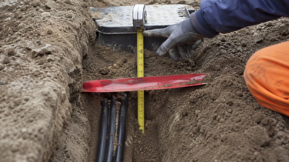
If the code requires, for example, a given cover above a PVC conduit, the installer cannot simply dig to that number and drop the conduit in. The top of the conduit must still sit at or below the required cover line after bedding and final grading are complete. That sounds obvious, but I have seen plenty of failed inspections caused by a nice straight trench that was simply too shallow once the inspector measured from finished grade.
For underground wiring, cover depth is normally measured from finished grade to the top of the cable, conduit, or raceway, not to the bottom of the trench.True
This is the common basis used in code burial tables and field inspection, although the exact wording and permitted wiring methods must be checked against the local electrical code and authority having jurisdiction.
Bedding material is not just there to make the trench look tidy. It controls point loading, abrasion, heat transfer, water movement, and long-term settlement around the cable system. Common choices include:
- Sand bedding, useful for protecting jackets from stones and creating a smooth bearing surface. It is easy to place, but in wet ground it can migrate if not confined properly.
- Screened native soil, often acceptable where it is free of sharp rock, construction debris, frozen lumps, slag, and organic material. It saves cost, but quality depends heavily on site discipline.
- Fine granular bedding, such as selected fines or small aggregate specified by the civil engineer. This is more controlled than random spoil and handles compaction better.
- Thermal backfill, used where ampacity depends on predictable soil thermal resistivity. This matters on heavily loaded feeders, duct banks, solar farms, EV charging infrastructure, and industrial distribution runs where heat dissipation becomes a design variable.
- Concrete encasement, used where mechanical protection, duct-bank formation, traffic loading, or utility standards require it. It improves physical protection but makes future repair slower, more expensive, and less forgiving.
The mechanism is straightforward: cable losses generate heat, and that heat must move through the insulation, jacket, bedding, soil, and eventually into the surrounding ground. Dry loose sand, poorly compacted spoil, or air voids around ducts can raise operating temperature compared with a denser engineered backfill. The trade-off is cost and constructability. Thermal or concrete-encased systems can improve predictability and protection, but they add labor, curing time, inspection points, and future excavation difficulty. For a short lightly loaded branch circuit, that may be overkill; for a long feeder running near its ampacity limit, it may be cheap insurance.
Separation from other services should be drawn before the trench is opened, not negotiated with a shovel in the hole. Exact clearances are local-code, utility, and project-specific, but the trench plan should account for:
- Water mains and service lines
- Gas piping
- Telecommunications and fiber ducts
- Stormwater and sanitary drainage
- Fuel lines and process piping
- Grounding electrode conductors and grounding grids
- Existing electrical ducts, street lighting circuits, and control cables
- Irrigation lines, heat-trace circuits, and site security cabling
Electrical separation is partly about mechanical damage and partly about maintenance access. A water repair crew should not have to expose an energized feeder to fix a leaking polyethylene service line. Gas utilities may also require specific horizontal and vertical clearances, crossing angles, tracer wires, sleeves, or warning tape colors. On industrial sites, I prefer a coordinated underground services drawing with a crossing schedule; it prevents the common mess where every contractor “just follows the fence line” and the last crew has nowhere safe left to dig.
Warning tape and route identification are cheap compared with a cable strike. Typical practice is to place warning tape above the cable or conduit, not directly on it, so the excavator or hand-digging crew finds the warning before contacting the electrical installation. The exact depth above the cable varies by jurisdiction and specification, but the intent is always early discovery. For larger sites, add:
- Durable surface route markers at changes in direction, road crossings, and termination points
- As-built drawings showing actual route, depth, conduit size, and cable type
- GPS or surveyed coordinates for feeders, duct banks, and critical crossings
- Photographs before backfill, with a tape measure or grade reference visible
- Inspection records tied to trench sections, not just a single project folder note
Cable handling deserves the same attention as depth. A properly buried cable that was damaged during pulling is still a bad installation. Check the manufacturer’s limits for:
- Minimum bending radius during pulling and final installed position
- Maximum pulling tension
- Maximum sidewall pressure at bends
- Cable drum orientation, rolling direction, storage, and lifting method
- Conduit fill and practical pulling clearance
- Pull box spacing, bend count, and access
- Pulling lubricant compatibility with the cable jacket and conduit material
- Protection at conduit ends, bell mouths, rollers, and temporary trench edges
This is where procurement and installation meet. A buyer may specify the correct armored or sheathed underground cable, but if the contractor drags it over broken concrete, pulls it through a rough conduit stub, or exceeds tension around two tight sweeps, the jacket can be compromised before energization. In practice, the most suspicious locations are conduit entries, duct bank exits, bends near foundations, and the first few meters off the drum where handling is rushed.
Water management is another trench detail that gets underestimated. Underground does not mean dry. Ducts should be sloped where the design calls for drainage, entries should be sealed against water and gas migration, and terminations should not sit at low points that collect trench water. In wet ground, consider whether the cable construction needs water-blocking features, whether spare ducts require caps, and whether the route crosses seasonal groundwater or irrigation zones. A flooded trench during installation is not automatically a failed job, but it changes the handling, inspection, and backfill conditions.
Backfill and final grade close the loop. The cover depth that passed inspection on Tuesday can become noncompliant after settlement if the trench was backfilled with loose spoil, organic material, or uncompacted lifts. Under paving, poor compaction becomes a maintenance problem too: the surface sinks, someone mills and repaves, and suddenly the electrical cover is less than intended. A good specification should define lift thickness, compaction requirements, acceptable backfill, exclusion of rocks and debris near the cable, and who verifies final grade before energization or handover.
The practical design target is not “deep enough on the drawing”; it is deep enough after bedding, pulling, backfill, compaction, and the site’s final surface are complete. That conclusion stops holding only where the local authority, utility owner, or equipment manufacturer imposes a more specific trench section, in which case their current requirement should control the build.
Inspection and documentation
Underground 240V work is not really “finished” when the cable is in the trench; it is finished when the installation can be proven after nobody can see it anymore. The inspection sequence should capture the route, cover depth, protection method, cable identity, and test condition before backfill hides the evidence.
Pre-installation verification
Before the trench crew starts cutting ground, the project file should match what is actually being installed. On a clean job, this is a short meeting with drawings on the tailgate; on a messy job, it prevents a week of arguments after the inspector asks why the conduit route moved around a drain line.
Verify these items before excavation:
- Approved drawings and latest revisions
Check that the trench route, panel source, load destination, risers, handholes, and crossing points match the issued construction set. Redlines are fine during construction, but uncontrolled sketches are how buried cable gets lost. - Cable datasheets and certificates
Confirm conductor material, conductor size, insulation voltage rating, sheath or armor type, temperature rating, and listed or specified suitability for underground use. For procurement teams, keep the supplier datasheet, compliance certificate, and batch or drum number together. Raceway schedule
Identify whether the run is direct-buried cable, PVC conduit, rigid metal conduit, intermediate metal conduit, duct bank, or another approved method. Burial depth acceptance often changes with the wiring method, so this cannot be left as a field assumption.Depth requirement and inspection hold points
Record the required minimum cover from the applicable code, permit, owner specification, or project standard. Mark any hold point where work must stop until inspection approval is received.Utility locates and permits
Confirm current utility markings, excavation permits, traffic or site access permits, and any private utility scans. Public locates do not always identify privately installed feeders, irrigation control wiring, gas yard lines, or old plant modifications.Trench route release
The proposed route should be walked with maintenance, operations, and civil/site personnel. That five-minute walk often catches future conflicts with forklift routes, slab cuts, sump drains, fence posts, or planned equipment pads.
Trench inspection before cable placement
The trench should be inspected before cable or conduit goes in, not after the crew has already committed the route. Look for:
- Depth measured from final grade or the defined finished surface, not from temporary spoil piles or rough excavation.
- Width sufficient for conduit spacing, bedding placement, compaction tools, and safe cable handling.
- Bedding material that matches the specification, typically clean sand or selected fill where required.
- Rock and debris removal, especially broken concrete, sharp stone, scrap rebar, and buried metal offcuts.
- Drainage conditions, including standing water, soft trench bottom, seasonal groundwater, or runoff paths from roofs and paving.
- Service clearances from gas, water, sewer, communications, process piping, grounding grids, and other electrical runs.
- Crossing details where the cable passes under roads, slabs, driveways, rail tracks, drainage ditches, or structural foundations.
- Route protection such as warning tape, marker posts, concrete cover, encasement, bollards, or mechanical protection at exposure points.
The mechanism is simple: poor bedding and sharp debris create point loading on the sheath, then soil settlement and thermal cycling work that damage into the jacket over time. The cable may test fine on day one and still have a shortened service life because the trench was treated like a disposal channel.
Cable installation inspection
Once the cable or conduit is being installed, inspect the work while it is still accessible:
- Outer jacket condition before and after pulling or laying, with any cuts, scuffs, flattening, or exposed armor investigated.
- Pulling records for long conduit runs, including pulling direction, lubricant used, crew notes, and any abnormal force or snagging.
- Bend radius at sweeps, handholes, panel entries, and direct-buried turns. Tight bends are common at risers because crews try to “make it fit” at the last two feet.
- Conduit entry protection, including bushings, bell ends, smooth transitions, and no sharp edges at sleeves.
- Grounding and bonding continuity for metallic raceways, armor, equipment grounding conductors, and transition fittings.
- Circuit identification at both ends, at accessible pull points, and on spare conduits where used.
- Sealing and water control at building entries, ducts, sleeves, and risers, especially where conduits slope toward equipment.
- Riser protection where underground wiring emerges above grade and is exposed to impact, sunlight, landscaping tools, livestock, or vehicles.
There is a trade-off here: tighter inspection hold points slow the civil crew, but they reduce re-excavation risk and warranty disputes. On industrial sites, I usually prefer one well-timed pre-backfill hold point with photos and measurements over a fast trench closure followed by three days of guessing.
Electrical testing before energization
Testing should be done after installation and before the circuit is energized, with results recorded rather than verbally reported. The exact tests and acceptable values must come from the applicable code, project specification, cable manufacturer, and equipment manuals.
Typical checks include:
- Continuity testing to confirm each conductor is intact end-to-end.
- Conductor identification to verify phase, neutral where used, and equipment grounding conductors are correctly landed.
- Insulation resistance testing with the test voltage, duration, temperature, humidity, and cable length recorded.
- Grounding and bonding checks across raceways, armor, grounding conductors, junction boxes, panels, and exposed metallic parts.
- Polarity checks where applicable, especially on single-phase loads, receptacle-style terminations, control transformers, and equipment feeds.
- Termination inspection for lug rating, conductor compatibility, torque records where specified, oxide inhibitor where required, and no insulation trapped under the lug.
Do not compare insulation resistance results casually between different cable lengths, temperatures, and insulation types. A long damp run will not behave like a short dry shop test sample, so the recorded conditions matter.
Documentation deliverables
A cable can meet product standards and still fail project acceptance if the installation records do not prove cover depth, routing, and protection before backfill. Product compliance says the cable was manufactured to the required construction; installation acceptance says the buried work was installed where and how the project required.
Keep these deliverables in the turnover package:
- Inspection photos showing trench depth with a tape, rod, or marked reference visible.
- Photos of bedding, conduit, cable placement, warning tape, crossings, risers, and backfill stages.
- Redline drawings showing route changes, added sleeves, relocated pull points, and revised termination locations.
- As-built route plan with dimensions from permanent references, not just “north of building.”
- Electrical test reports with instruments used, dates, environmental conditions, and technician identification.
- Cable certificates, datasheets, purchase records, drum numbers, and batch traceability.
- Permit sign-offs, inspection approvals, nonconformance reports, and corrective action records.
- Maintenance records noting buried route restrictions, future excavation warnings, and locator information.
A compliant underground cable can still fail project acceptance if the installer cannot prove the required burial cover, routing, and protection before backfill.True
Product certification addresses cable construction; project acceptance also depends on installation evidence required by the contract, permit, inspector, or owner specification.
This level of documentation is most valuable for permanent plant feeds, commercial service runs, and any installation likely to be modified later. For a small private installation the file may be simpler, but the principle does not change: once the trench is closed, photos, test sheets, and as-built records become the only practical evidence of what was buried.
Failure risks underground
Most underground 240V failures are not caused by the nominal voltage; they come from the wrong burial depth, the wrong cable construction, poor trench materials, or a protection method that did not match the site. A shallow cable that survives the first inspection can still become a fault, outage, or shock hazard years later when somebody drives a fence post, cuts a trench, or changes the finished grade.
Mechanical damage is the obvious risk, and it is the one plant people usually discover the hard way. A cable buried just below topsoil may be safe on paper only until normal site work begins:
- Gardening tools and landscape work: spades, edging machines, irrigation repairs, and tree planting can nick a sheath or cut into direct-buried cable. A small jacket cut may not trip a breaker immediately, but it gives moisture a starting point.
- Trenching machines and augers: utility trenchers, post-hole augers, sign anchors, bollard foundations, and fence posts can penetrate far deeper than hand tools. Marking tape helps only if it is placed above the cable at a useful warning height and the operator notices it.
- Grading and surface changes: removing 100 mm of soil during yard rework can turn a compliant installation into an under-depth installation. I have seen this around loading areas where gravel is scraped and re-laid every few seasons.
- Rocks and poor bedding: angular stone against a sheath acts like a slow cutter under soil movement and vibration. Sand or screened bedding is not cosmetic; it spreads pressure and removes point loads.
- Settlement and heavy vehicle loads: compacted fill, forklifts crossing an outdoor yard, delivery trucks, and temporary cranes can transfer load into the trench. Shallow rigid conduit can crack; shallow direct-buried cable can be squeezed against stones or debris.
- Rodents and pests: rodents do not respect cable schedules. Armoring, conduit, harder sheath materials, and route selection matter in sites with stored grain, feed, waste handling, or warm equipment pads.
Moisture turns minor damage into electrical failure. Once the outer sheath is breached, water can migrate along the cable, especially where installation damage has opened a path around armor, screens, fillers, or bedding. Insulation degradation is not always dramatic; low insulation resistance may creep down over months, then show itself after heavy rain or seasonal thaw. Metallic armor, screens, or concentric conductors can corrode if the sheath system is compromised, and corrosion can reduce the reliability of grounding or shielding functions. At terminations, moisture plus dirt creates tracking paths across insulation surfaces, particularly where glands are loose, conduit entries point upward, or junction boxes sit in low ground.
A waterproof outer jacket does not make every 240V cable suitable for direct burial.True
Direct-burial suitability depends on the full cable design, sheath material, mechanical protection, moisture resistance, installation environment, and applicable code or standard, not on jacket appearance alone.
Thermal failure is less visible but just as expensive. Current creates heat in the conductor; that heat must move through insulation, sheath, bedding, soil, and the surrounding ground. If the conductor is undersized, circuits are heavily grouped, the soil is dry and thermally resistive, or the trench is packed with poor backfill, the cable may run hotter than expected. Deep burial can protect against mechanical damage, but it can also make heat dissipation worse in some installations because the heat path to ambient air is longer and the surrounding soil may retain heat.
That is the trade-off buyers and engineers sometimes miss: more cover is not automatically better if ampacity has not been checked. For lightly loaded branch circuits the margin may be generous, but for continuous loads such as pumps, heaters, compressors, EV charging, production equipment, and outdoor distribution feeders, conductor size and installation method must be evaluated together. The conclusion stops holding where load current, grouping, soil condition, and duty cycle differ from the assumptions in the code table or supplier data.
Electrical faults usually appear after one or more mechanical, moisture, or thermal weaknesses has already started. The common failure modes are:
| Fault or defect | Typical path to failure | Why it matters |
|---|---|---|
| Phase-to-ground fault | Damaged insulation contacts armor, earth, conduit, or a grounded enclosure | Shock risk, equipment trip, fire risk if fault clearing is poor |
| Phase-to-phase fault | Two insulated conductors are cut, crushed, overheated, or water-tracked | High fault energy, breaker operation, cable replacement likely |
| Neutral failure | Loose splice, corroded conductor, damaged neutral in multi-wire circuits | Unstable voltage, equipment damage, difficult troubleshooting |
| Poor grounding or bonding | Corroded armor, bad conduit continuity, loose termination, wrong fittings | Protective devices may not clear faults fast enough |
| Damaged conduit entry | Sharp edge, failed gland, open sweep, water-filled raceway | Cable jacket abrasion and long-term water exposure |
| Inadequate fault clearing | Wrong breaker, high impedance fault path, poor coordination | Fault persists longer than the cable or enclosure can tolerate |
Symptoms are often intermittent before they become a clean failure. Maintenance teams should not ignore:
- nuisance trips after rain, washdown, or irrigation;
- voltage drop under load, especially on motor starts;
- intermittent PLC, drive, pump, gate, charger, or lighting faults;
- warm terminations, discolored lugs, or brittle insulation near glands;
- low insulation resistance readings compared with earlier test records;
- visible ground disturbance, sinkage, new posts, or recent excavation along the route;
- recurring breaker operation that returns after reset without an obvious load-side cause.
The commercial damage is rarely limited to the cost of cable. Emergency excavation means finding the route, obtaining permits or dig clearance, cutting pavement or landscaping, exposing other utilities, and stopping production or site operation while the fault is isolated. A failed underground feeder to a pump station, workshop, refrigeration unit, charger bank, or outdoor process skid can cost far more in lost output than in copper and insulation. Contractors face failed inspection, warranty disputes, insurance questions, and reputation damage when depth records, cable markings, test sheets, or as-built routes cannot prove that the installation was specified and buried correctly.
Procurement specification checklist
Use the inquiry package to remove guesswork before anyone prices cable. A supplier cannot quote underground 240 V cable responsibly from “240 V, buried, 500 m” alone; they need the electrical duty, installation method, compliance target, and delivery constraints that drive conductor size, sheath, armoring, testing, and drum planning.
1. Define the electrical duty
Give the supplier the actual circuit conditions, not just the nominal voltage.
- System voltage and configuration: state whether it is 240 V single-phase, split-phase, line-to-line on a three-phase system, or another local arrangement.
- Phase and core requirement: single-phase two-wire, single-phase with neutral, three-phase without neutral, three-phase with neutral, plus protective earth requirement.
- Load current and load type: continuous motor load, heater bank, pump, charger, lighting feeder, temporary construction power, or mixed load.
- Allowable voltage drop: give the project limit and whether it applies at full load, starting load, or both. Long underground runs can move the design from a thermal sizing problem to a voltage-drop problem very quickly.
- Fault level and protective device: breaker or fuse type, rating, trip curve, upstream fault current if known, and required disconnection time.
- Grounding arrangement: TN, TT, IT, local earthing electrode, separate protective conductor, armor-as-earth if permitted, or dedicated earth core.
- Duty cycle: continuous, intermittent, seasonal, standby, cyclic motor starts, or emergency use.
The mechanism is simple but often missed: load current heats the conductor, route length creates voltage drop, and fault level determines whether the cable and protective device work together during a short circuit. If one of those is wrong, the cable may still “fit the trench” but fail the electrical design.
2. Specify the cable construction
For underground 240 V power cable, the construction line in the purchase specification should be explicit.
- Conductor material: copper or aluminum, with class and stranding requirement if relevant.
- Conductor size: requested size, or ask the supplier to size it against load, length, installation method, and voltage-drop limit.
- Number of cores: including neutral and protective conductor arrangement.
- Insulation material and voltage rating: for example XLPE or PVC, with rated voltage class suitable for the applicable standard and system.
- Outer sheath material: PVC, PE, LSZH, or other project-required compound.
- Armor or metallic screen: steel wire armor, tape armor, concentric conductor, screen, or no armor depending on mechanical risk and local practice.
- Water blocking: longitudinal or radial water-blocking if the route is wet, flood-prone, or difficult to access later.
- Temperature rating: conductor operating temperature and short-circuit temperature rating.
- Flame, smoke, and halogen requirements: especially where the cable enters buildings, tunnels, substations, or industrial control rooms.
- Standard compliance: quote the exact required standard, edition if known, and any project specification that overrides it.
Copper gives compact size and easier terminations, but aluminum can be commercially attractive on long feeders if lugs, bending radius, pulling practice, and voltage drop are handled properly. Armor improves mechanical protection and may help with grounding schemes where allowed, but it increases diameter, weight, bending radius, pulling load, and drum handling effort. That trade-off flips on sites with rocky backfill, vehicle traffic, or poor excavation control.
3. State the installation conditions
Burial depth belongs in the cable inquiry because it affects protection, rating, and accessories.
- Installation method: direct burial, PVC conduit, HDPE duct, rigid metal conduit, cable tray before burial, or mixed route.
- Required cover depth: state the project requirement and the authority or code basis if available.
- Trench environment: sand bedding, native backfill, crushed rock, concrete encasement, ducts in bank, warning tape, marker posts, or detectable tape.
- Soil data if available: thermal resistivity, moisture condition, corrosivity, pH, salinity, contamination, and drainage.
- Ambient and ground temperature: design values, not just average weather.
- Cable grouping: single circuit, multiple circuits, spacing between cables or ducts, and any parallel feeders.
- Route length and layout: total length, straight sections, bends, elevation changes, risers, building entries, road crossings, rail crossings, and wet areas.
- Termination method: glands, lugs, heat-shrink kits, cold-shrink kits, junction boxes, panels, transformers, or equipment terminals.
In practice, buried cables lose heat through soil, bedding, conduit wall, and surrounding ground. Dry soil, duct banks, tight grouping, and high ambient temperature reduce ampacity, so a cable that is electrically adequate in open air may be undersized underground. The limit of this checklist is that final burial depth and installation approval still sit with the local code authority, inspector, or project engineer of record.
4. Require compliance and quality documents
Do not leave documentation until after the cable ships. Put it in the purchase order.
- Applicable cable standard and project specification.
- Third-party certificates where required by the destination country or end user.
- Manufacturer test certificates.
- Factory routine test records.
- Inspection and test plan, if the project needs witness or hold points.
- Conductor, insulation, sheath, and armor traceability requirements.
- Packing list, cable drum schedule, gross weight, net weight, and dimensions.
- Drum identification linked to cable length, type, batch, and test record.
- Installation manuals, handling limits, minimum bending radius, and pulling tension limits.
For utility, mining, industrial, and infrastructure buyers, traceability is not paperwork for its own sake. It is what lets maintenance teams identify the correct installed drum ten years later when a feeder is extended, damaged, or audited.
5. Lock down logistics before production
Underground cable is heavy, awkward, and expensive to rework once it is cut to length.
- Project country and applicable import requirements.
- Delivery port, warehouse, or site address.
- Required drum lengths and tolerance.
- Maximum drum diameter or weight the site can unload.
- Packaging protection for sea freight, outdoor storage, humidity, and long transit.
- Cable marking language, meter marking, voltage marking, and project tag.
- Label format for procurement, warehouse, and installation crews.
- Required installation window and phased delivery schedule.
- Spare length strategy for terminations, routing changes, and future repair.
Longer drums reduce joints, which is usually good underground, but they can exceed forklift capacity, road limits, or cable-pulling limits. Shorter drums are easier to handle but introduce more joints, more inspection points, and more future failure locations.
6. Bring the manufacturer in early on bulk orders
Early supplier review is most valuable before the buyer freezes conductor size, sheath type, armor design, and drum schedule. On bulk underground projects, small specification changes can affect ampacity derating, production lead time, minimum order quantities, accessory compatibility, and the way installers actually pull and terminate the cable.
Jinda is well positioned for this kind of coordination because it operates as a dedicated cable manufacturer with R&D, production, sales, technical support, and after-sales service under one system. For international buyers managing repeated underground cable packages, that matters: the same specification has to be manufacturable, testable, documented, packed correctly, and repeatable across shipments.
Send a clear specification rather than a price-only request. The better the input package, the less the quotation depends on assumptions, and the fewer surprises show up later as oversized drums, missing certificates, incompatible glands, voltage-drop disputes, or cable that meets the purchase line but not the site.
Frequently asked questions
Is 12 inches deep enough for a 240V cable?
Usually, no. A 12-inch cover is often too shallow for ordinary unprotected underground 240V power cable, especially for a branch circuit feeding equipment, a workshop, a pump, or an outbuilding.
There are code exceptions in some jurisdictions for specific protected circuits, specific cable/raceway methods, GFCI-protected low-voltage-to-ground arrangements, or installations under defined residential conditions. Do not treat 12 inches as a general design depth. If the installation depends on an exception, the drawing, permit notes, and inspector approval should all say so before the trench is opened.
Can 240V cable be buried without conduit?
Yes, but only if the cable is specifically manufactured and marked for direct burial, and the installation still has to meet the required cover depth. A standard indoor cable, flexible cord, tray cable without the right rating, or building wire pulled loose into soil is not acceptable just because it is insulated.
Direct-buried cable still needs attention at weak points:
- Where it rises out of the ground
- Where it enters a building, cabinet, pedestal, or motor control panel
- Where it crosses rocky fill, demolition debris, or compacted aggregate
- Where future digging is likely, such as near fence lines, irrigation routes, or loading areas
In practice, the vertical stub-ups are where I see most damage: a mower strike, a forklift tine, or someone leaning a pallet against a riser. Even direct-burial cable often needs conduit sleeves or guards at those locations.
Is conduit always better than direct burial?
No. Conduit gives better mechanical protection and may make future replacement easier, but it costs more, takes longer to install correctly, and can create its own problems if poorly designed.
The tradeoff looks like this:
| Installation method | What it does well | What can go wrong |
|---|---|---|
| Direct-buried rated cable | Fewer parts, faster trench work, good for long simple runs | Harder to replace, vulnerable if depth or bedding is poor |
| PVC conduit | Corrosion-resistant, common, economical, easier cable replacement in some layouts | Long pulls can be difficult; joints and sweeps must be planned |
| Rigid metal conduit | Strong mechanical protection, useful under traffic or exposed risers | Higher cost, corrosion concerns, bonding and coating details matter |
| Oversized conduit system | Better pulling margin and future capacity | Higher material cost; may reduce heat dissipation depending on fill and installation |
Conduit also fills with water. That is not a workmanship myth; underground raceways should be assumed wet unless proven otherwise. Cable inside underground conduit must have insulation suitable for wet locations, and pulling tension has to be checked on long runs with multiple bends.
How deep should cable be under a driveway?
Cable under a driveway often needs either greater cover, stronger raceway protection, or both. The required detail depends on vehicle loading, paving structure, soil compaction, local electrical code, and the approved site drawing.
A light residential driveway is not the same as a plant entrance used by delivery trucks. Repeated wheel loads can settle backfill, crack shallow raceway, or expose risers near slab edges. For commercial and industrial sites, I would expect the electrical drawing to coordinate with the civil drawing, especially where the route crosses:
- Concrete aprons
- Asphalt drives
- Forklift routes
- Truck turning areas
- Yard drainage trenches
- Future slab expansion zones
Does 240V need to be deeper than 120V?
Not automatically. Burial depth is usually controlled more by wiring method, circuit protection, location, and mechanical risk than by the difference between 120V and 240V alone.
A protected residential 120V branch circuit and a protected 240V branch circuit may fall under similar burial rules in some codes, while an unprotected direct-buried feeder may require more cover. Higher voltage can matter when the installation moves into another code category, utility rule, or industrial distribution class, but for common 240V premises wiring, voltage alone is not the deciding variable.
Burial depth for underground 240V cable is determined by voltage alone.False
Cover depth is normally based on the wiring method, protection, location, circuit characteristics, and the authority having jurisdiction. Voltage is only one part of the classification.
Where should warning tape be placed?
Warning tape is normally installed above the cable or conduit, with enough vertical separation that an excavator encounters the tape before reaching the electrical installation. The exact placement should follow the project specification or local code requirement.
A common field mistake is laying tape directly on top of the conduit. That gives almost no warning. On deeper trenches, tape is often placed partway up the backfill, after the first controlled layer is placed and before final backfill. For high-risk sites, drawings may also require detectable tape, tracer wire, marker posts, or as-built coordinates.
Who approves the final burial depth?
Final approval usually sits with the authority having jurisdiction, but several parties influence the accepted depth before the inspector ever arrives.
Typical roles are:
- Electrical designer: Specifies wiring method, cover, protection, and route.
- Licensed installer: Builds the trench and installation to the approved design.
- Local inspector: Verifies code compliance before backfill where inspection is required.
- Utility: Approves service laterals or utility-owned portions, if involved.
- Site owner or facility engineer: Confirms route safety, future access, and plant standards.
- Authority having jurisdiction: Has the final say where code interpretation is disputed.
For industrial work, I like to see the required cover depth written on the trench inspection form, not just buried somewhere in a drawing note.
What information should I give a cable manufacturer?
Give the manufacturer enough information to confirm the cable construction, compliance documents, packaging, and delivery plan. “240V underground cable” is not a complete purchasing description.
At minimum, provide:
- Rated voltage and system type
- Conductor material and size
- Number of cores or conductors, including grounding conductor requirements
- Insulation type and temperature rating
- Direct-burial or conduit installation method
- Required cover depth, if it affects sheath, armor, or protection requirements
- Soil or site conditions, such as moisture, chemicals, oil, salinity, rodents, or abrasion
- Armoring, metallic screen, sheath, or jacket requirements
- Applicable standards and certificates
- Inspection, test report, and compliance documentation requirements
- Drum length, packing method, destination, and delivery schedule
For bulk procurement, clear installation information prevents the common mismatch: a cable that meets voltage rating on paper but lacks the sheath, armor, certification, or wet-location suitability needed for the actual trench.
Verify your burial specification
Use this final check before approving drawings, issuing a purchase order, or closing an inspection hold point. The required burial depth for a 240V circuit is not locked in until the applicable local electrical code, authority requirements, wiring method, and site conditions have all been confirmed.
- Confirm the governing rule first.
Identify the local electrical code, utility rule, project specification, and authority having jurisdiction before treating any depth table as final. A residential feeder, a farm outbuilding circuit, a factory yard supply, and a port-area installation can all involve different inspection expectations even if the nominal voltage is the same. Define the circuit duty.
Record the load type, operating current, starting current, duty cycle, phase arrangement, earthing system, route length, and whether the circuit feeds fixed equipment, lighting, pumps, chargers, HVAC, or general distribution. This affects conductor size, voltage drop, thermal loading, and sometimes the required mechanical protection.Select the wiring method.
Decide whether the installation will use direct-buried armored cable, cable in PVC conduit, cable in rigid metal conduit, duct bank, or another approved raceway system. In practice, this decision often changes the cover depth, trench width, pulling method, bend allowance, and repair strategy years later.Confirm the required cover depth.
Check the specified cover from finished grade to the top of the cable, conduit, or raceway, not simply the trench excavation depth. Allow for bedding thickness, warning tape position, imported fill, compaction, future grading, and settlement. I have seen compliant-looking trenches fail inspection because the crew measured from the temporary scraped surface rather than final grade.Check site exposure.
Review vehicle traffic, paving, frost movement, rocky soil, drainage, rodents, chemicals, UV exposure at risers, and the risk of later excavation. A clean garden trench and a forklift-crossed service yard do not deserve the same cable protection, even if both carry 240V.Validate ampacity and voltage drop.
Burial depth does not replace electrical sizing. Soil thermal resistivity, grouping with other circuits, conduit fill, ambient temperature, conductor material, and route length can all push the design toward a larger conductor. Long 240V runs are especially easy to undersize if the buyer only asks for “burial-rated cable” without load and distance data.Document the trench details.
Keep the route drawing, cable schedule, depth record, bedding and backfill notes, warning tape location, conduit type, joint locations, test records, and inspection photos. For industrial sites, mark coordinates against fixed references, not just a fence line that may move during the next expansion.Inspect before backfill.
Do not bury unresolved questions. Verify depth, support, bend radius, separation from other services, conduit joints, cable identification, riser protection, and continuity or insulation test requirements before the trench disappears.

The buying decision should not be based on burial depth alone. The correct underground 240V cable must also match the insulation rating, conductor size, sheath or armor protection, environmental exposure, installation method, testing requirements, and compliance documentation expected by the project. A cable that is legal in one buried arrangement may be unsuitable in another if the sheath, armor, conductor temperature rating, or certification package does not match the specification.
For bulk procurement, send the cable supplier the information that normally decides the construction:
- Project location and applicable electrical standard or client specification
- Single-line diagram or circuit schedule
- Voltage, phase, frequency, load current, and starting conditions
- Route length and acceptable voltage drop
- Installation method: direct burial, conduit, duct bank, tray-to-trench transition, or risers
- Soil, moisture, chemical, traffic, and temperature exposure
- Required conductor material and size, if already engineered
- Insulation, sheath, armor, flame, UV, oil, or termite-resistance requirements
- Inspection, testing, marking, packing, and compliance document requirements
- Estimated quantity, drum length preference, delivery destination, and project timing
Jinda’s technical and sales team can review your underground 240V cable requirement, recommend a suitable cable construction, confirm the documentation needed for the project, and prepare a quotation for international supply. Send the drawings, load data, installation conditions, and required compliance standards before placing the order; that is the point where a cable inquiry becomes an installable specification rather than a risky line item.