A power cable that gets nicked by a backhoe, crushed under a pallet truck, or chewed in a damp service trench does not fail politely. It trips production, creates fault-finding work nobody scheduled, and can turn a cheap cable purchase into excavation, downtime, and replacement labour. Steel wire armoured cable is used where the installation needs a power cable that can take mechanical abuse without relying entirely on conduit or perfect site discipline.
Steel wire armoured cable is used where power circuits need mechanical protection: underground feeds, outdoor plant areas, factories, utilities, construction sites, rail and infrastructure projects, and building services. It suits fixed installations exposed to impact, crushing, rodents, or rough handling, provided voltage rating, sheath material, earthing, and local installation rules are matched.
The useful question is not “Is SWA strong?” but “What kind of risk is the cable being asked to survive?” A buried 0.6/1 kV site supply, a medium-voltage feeder across a utility corridor, and a damp pump-house circuit all push the cable in different ways. The right use case depends on load, environment, burial depth, bending space, termination method, and how maintenance crews will actually handle the installation five years from now.

Typical SWA service locations
SWA cable is normally chosen for fixed power routes where the cable may be buried, exposed to plant traffic, routed outdoors, or installed close to equipment that can damage ordinary sheathed cable. The industry label matters less than the route condition: if the circuit is fixed, power-carrying, and realistically at risk from impact, compression, tools, rodents, or rough access, SWA becomes a practical candidate.
Underground power distribution
Underground feeders are one of the most common SWA applications. Typical routes run between transformers, main switchboards, distribution boards, workshops, pumping stations, gatehouses, package equipment, and outdoor panels. Some are direct-buried; others are pulled through ducts for route control and future replacement.
The armour helps where the cable may face:
- Soil pressure and settlement.
- Sharp stones or backfill contamination.
- Hand tools during later maintenance.
- Shallow excavation by contractors who were “only digging a small trench.”
- Rodent activity, depending on site conditions.
- Local compression where the route crosses yards, access roads, or equipment pads.
In practice, the civil work matters as much as the cable. Good bedding sand, warning tape, route markers, and correct burial depth do more for service life than buying an armoured cable and throwing it into rubble. Common direct-burial cover can sit roughly in the 450 to 1000 mm range, but the actual requirement depends on local code, traffic loading, mechanical protection, and utility practice. A truck yard and a landscaped area are not the same installation.
Duct installation changes the risk profile. The duct protects against soil and casual disturbance, but the cable still sees pulling tension, sidewall pressure, water accumulation, and possible damage at chamber entries. SWA is often kept in the design because the cable may be exposed in pits, risers, terminations, or future repair work.
Industrial plants and heavy workshops
Steel mills, cement plants, petrochemical facilities, mining surface infrastructure, water treatment plants, manufacturing lines, and heavy fabrication shops are natural SWA territory. Cables may run on ladder trays, in trenches, along walls, under platforms, or down to motors and local control panels.
The damage mechanisms are not subtle:
- Forklift and pallet impact near floor level.
- Falling tools, slag, aggregate, scrap, or maintenance parts.
- Vibration from crushers, pumps, conveyors, and compressors.
- Hot or dusty environments that age outer sheaths faster.
- Washdown water, chemical mist, or process contamination.
- Poor access that leads technicians to stand on trays or drag chains across them.
A cement plant cable gallery, for example, is rarely clean for long. Dust packs into trays, covers labels, and hides small sheath damage until a shutdown inspection. In a steel or mining environment, a cable route that looked protected on a drawing can become exposed after one modification to a chute, guard, or walkway.
The trade-off is handling and termination effort. SWA is heavier and stiffer than equivalent unarmoured cable, and large multicore sizes need proper glands, support spacing, bending allowance, and trained installers. Minimum bending radius is commonly in the 12 to 20 times overall diameter range, subject to the cable design and applicable standard. If the route is tight, frequently modified, or packed into a congested panel entry, the armour that protects the cable can also make installation slower and more expensive.
Commercial and institutional buildings
SWA is also used in buildings, especially where fixed wiring passes through rough service areas rather than finished office zones. Common locations include:
- Service entrances and utility rooms.
- Sub-main distribution between switchboards and distribution panels.
- Plant rooms, boiler rooms, and chiller areas.
- Basements and underground car parks.
- Vertical risers, where allowed by the project specification.
- Rooftop equipment feeds.
- External lighting, signage, gate, and security circuits.
Here the need is usually not “heavy industry” protection. It is robust fixed wiring between electrical spaces where conduit may be impractical, access is shared with other trades, and mechanical damage is credible. Basement car parks are a good example: vehicles, pipework, trays, drainage, and later maintenance all compete for space. A cable clipped neatly today may be beside a new sprinkler line or ventilation bracket next year.
Fire performance, smoke requirements, routing in escape paths, and earthing design must be checked against the local building code and project specification. Standard PVC-sheathed SWA is not automatically suitable for every building area. Some projects require low-smoke, halogen-free, fire-resistant, or circuit-integrity cable constructions instead.
Outdoor utility and infrastructure projects
Street lighting, traffic control systems, drainage stations, tunnels, bridges, rail facilities, airport ground systems, telecom power rooms, utility yards, and public works sites often use SWA because exposure and access control are imperfect. Cabinets sit outdoors. Routes pass through handholes. Cables emerge at columns, poles, pumps, barriers, and equipment plinths.
The useful feature is not only the steel wire layer. It is the full installation system: glands, earth continuity, route marking, sealing, bending control, and protection at entries. A street lighting cable may be buried for most of its route, then become vulnerable at the base of a column where water, corrosion, and mechanical knocks are concentrated. That transition point deserves more attention than the middle of the trench.
For bridges and tunnels, designers also need to consider fire behavior, corrosion exposure, ventilation, emergency operation, and maintainability. Armour gives mechanical protection, but it does not turn a general-purpose cable into a fire-survival cable or a corrosion-proof system.
Energy and resource projects
Solar farms, wind farm balance-of-plant systems, battery energy storage sites, oil and gas support areas, pump stations, and substations often have long outdoor cable runs. SWA may be used for AC feeders, auxiliary power, controls power, and distribution circuits where voltage class and project standards allow. Common low-voltage SWA ratings include 0.6/1 kV, while medium-voltage armoured power cables commonly cover classes such as 3.6/6 kV through 18/30 kV, with higher classes specified by project.
Long routes shift the decision from “will it survive a bump?” to “can the project install, test, terminate, and maintain kilometers of this cable without creating future faults?” Voltage drop, short-circuit duty, conductor temperature rating, soil thermal resistivity, grouping, duct fill, and pulling sections all matter. PVC insulation is commonly associated with 70 °C conductor temperature ratings, while XLPE or EPR insulation is commonly associated with 90 °C, but the actual rating belongs to the applicable standard and compound, not a generic product name.
On large sites, SWA is often selected because it tolerates the construction environment as well as the operating environment. That matters on solar and storage projects, where civil crews, trenching crews, electrical contractors, and commissioning teams may overlap in the same corridors.
Ports, shipyards, and marine-adjacent land installations
Ports and shipyards use armoured land power cables for quay cranes, shore-side distribution, warehouses, workshops, container yards, lighting, pumps, and service pedestals. These routes see vehicle traffic, salt-laden air, standing water, vibration, and mechanical abuse from cargo handling. Cable supports and glands need corrosion attention; ordinary mild-steel hardware in a coastal yard can look tired very quickly.
There is a clear distinction, though: land-based SWA cable is not the same as specialized marine shipboard cable. Shipboard cables may need different approvals, fire behavior, oil resistance, flexibility, and installation rules. A shore power feeder across a quay and a cable installed inside a vessel are different design cases, even if both are near seawater.
Construction and temporary site power
SWA can be suitable for fixed temporary routes feeding site distribution boards, tower crane supplies, dewatering pumps, hoists, site offices, and semi-permanent construction services. It is often chosen where the cable can be clipped, buried, protected, or routed along a defined corridor for months.
The limit is movement. Standard SWA is not a trailing cable. If a cable will be repeatedly dragged, coiled, run across mud, moved by hand, or connected to mobile equipment, a flexible rubber-sheathed trailing cable is usually the better engineering choice. I have seen sites try to use armoured cable like a heavy extension lead; the usual result is damaged glands, cracked sheath near terminations, and nuisance faults that appear at the worst possible time.
Agricultural and remote facilities
Farms and remote sites use SWA for irrigation pumps, boreholes, grain stores, barns, rural workshops, perimeter systems, water treatment skids, and outbuildings. Long distances, burial, rodents, livestock, tractors, and limited maintenance access all push the choice toward mechanically protected cable.
Agricultural installations are deceptively harsh. Fertilizer, damp bedding, slurry, UV exposure, and improvised repairs can shorten cable life. A route to a borehole pump may be electrically simple but physically exposed for years, especially where it crosses field edges, gates, and service tracks. Correct cable sizing also matters because long rural runs can suffer voltage drop and motor starting problems before the cable reaches its current-carrying limit.
Data centers and critical facilities
Data centers, hospitals, laboratories, and critical process sites may use SWA for generator connections, outdoor chillers, pump sets, UPS distribution, fuel systems, and plant-area feeders. These facilities value predictable fault protection, robust routing, and fewer accidental outages during maintenance works.
The selection is conditional. Fire performance, electromagnetic considerations, earthing and bonding strategy, segregation, redundancy philosophy, and local authority requirements can override the simple desire for armour. A generator yard feeder may be a strong SWA application; a cable in a sensitive internal riser or escape route may require a different construction altogether.
SWA cable selection should be based on the route damage risk and fixed power duty, not simply the industry sector.True
The same facility can contain clean indoor routes where unarmoured cable in containment is adequate and exposed, buried, or plant-adjacent routes where armour is justified.
Across all these locations, the repeating pattern is clear: SWA is selected where a fixed power cable has to survive a credible mechanical damage path. The conclusion stops holding when the route needs frequent flexing, special fire survival, extreme chemical resistance, marine shipboard approval, or a cable construction defined by another project standard. In those cases, armour may still appear in the specification, but it is no longer the main selection driver.
Mechanical risks the armour addresses
Steel wire armour is selected because it gives a fixed power cable a sacrificial mechanical layer between the live cores and the outside world. It improves survival against impact, crushing, scraping, animal attack, and some installation abuse, but it does not make the cable waterproof, indestructible, or electrically correct by itself.
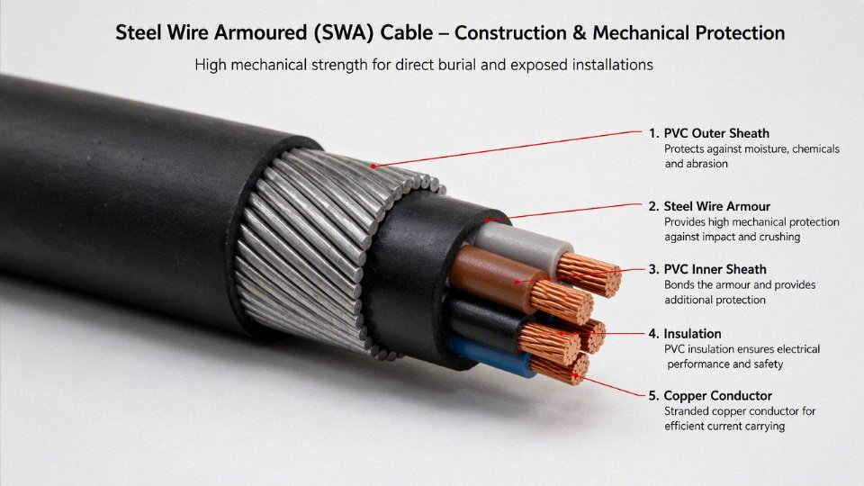
The engineering mechanism is simple enough: galvanized steel wires sit over the bedding and under the outer sheath, spreading local force around the cable circumference instead of letting one sharp point drive straight into the insulation system. That buys margin in places where the cable route is not clean, controlled, and gentle. In practice, those are exactly the places most factory and site cables end up.
Impact and crushing
SWA is useful where a cable may be hit, pressed, or loaded after installation. Typical plant-floor risks include:
- Dropped spanners, scaffold clamps, grinder bodies, or coupling halves
- Stones and brick fragments in trench backfill
- Foot traffic over temporary exposed runs
- Forklift pallet contact near wall-mounted routes
- Compression in congested trays where other services are added later
- Local pressure points where a cable crosses steelwork, concrete edges, or tray lips
The armour does not stop all deformation. What it does is reduce the chance that a single blow cuts the sheath, bedding, and insulation in one event. A round stone in backfill may only dent the outer sheath; a sharp piece of scrap steel under load is a different problem. This is why I still want sand blinding, screened backfill, cable tiles, or ducts on buried routes where the civil crew has a habit of “making the trench disappear” with whatever spoil is next to the excavator.
There is a trade-off. Armour increases cable diameter, weight, bending stiffness, gland size, and pulling effort. On long tray runs, that can mean more tray loading, larger rollers, and two extra people on the pull. The preferred choice can flip where the route is fully enclosed in a clean metallic conduit or panel trunking and the main constraint is termination space, heat dissipation, or pulling tension rather than external abuse.
Abrasion and scraping
SWA is more tolerant than unarmoured power cable when the route involves rough handling, duct entries, ladder tray transitions, and industrial corridors with metal brackets everywhere. The outer sheath still takes the first wear, but the armour layer gives a second line of defense before damage reaches the bedding and cores.
Common abrasion points include:
- Duct mouths without bellmouths or proper sleeves
- Tray edges cut on site and left with burrs
- Cable cleats overtightened by impact drivers
- Pulls around concrete corners or through wall sleeves
- Routes shared with compressed air pipe, hydraulic hose, or instrument trays
- Vibration zones near pumps, crushers, conveyors, and fan skids
The mechanism here is not magic hardness. It is layered damage tolerance. A scrape that would remove enough sheath from an unarmoured cable to expose insulation may only expose or polish part of the armour on an SWA cable. That still needs inspection and repair judgement, because exposed steel can corrode, and a compromised sheath may allow moisture into the cable construction.
Rodent and pest attack
Steel wire armour is a much stronger physical barrier than polymer sheath alone. In substations, farm buildings, outdoor kiosks, warehouses, tunnels, and food-related facilities, that matters because rodents often attack cable sheaths at quiet edges, warm areas, or along wall-floor junctions.
Steel wire armour makes a cable completely rodent-proof.False
The armour is a strong deterrent and mechanical barrier, but severe animal activity, damaged sheaths, exposed terminations, glands, joints, and non-armoured tails can still create failure points. Pest control and route protection remain part of the design.
The weak spots are often not the middle of the cable. They are:
- Gland entries with damaged shrouds
- Exposed single-core tails inside equipment
- Joints sitting in damp pits
- Cable bends where the sheath was nicked during pulling
- Places where baiting and housekeeping are ignored because “the cable is armoured”
No standard cable should be treated as immune in a severe pest environment. If the site has recurring rodent damage, the cable specification is only one control. You still need sealed penetrations, clean cable trenches, pest management, and inspection access.
Burial-related hazards
Direct burial is one of the main reasons buyers ask for SWA, but armour does not replace civil work. It reduces the probability of damage from ordinary soil pressure, minor settlement, stones, and reasonable backfill variation. It does not make careless burial acceptable.
A buried cable route should still address:
- Minimum cover, commonly somewhere around 450 to 1000 mm depending on local code, vehicle loading, and mechanical protection
- Sand or fine bedding where native soil contains sharp stones or construction debris
- Cable warning tape above the cable, placed at a depth where excavators see it before they reach the service
- Protective tiles, slabs, or ducts where future digging is likely
- Route markers, drawings, and as-built records that maintenance staff can actually find
- Separation from hot pipes, steam condensate lines, and other services that change cable temperature
- Drainage, groundwater, chemical contamination, and soil corrosivity where relevant
Soil movement is a slow failure mechanism. Settlement or cyclic wet-dry ground can impose bending and point loads over years, especially at building entries, trench crossings, and duct exits. The armour helps the cable tolerate those movements, but poor bedding can still create a hard pressure point that eventually damages the sheath or distorts the cable.
Excavation risk is different. Armour may survive a light shovel strike or reduce damage from a glancing scrape. It is not designed to defeat a backhoe tooth. If the site expects future excavation, physical route protection and permit-to-dig discipline matter more than simply choosing a heavier cable.
Fault containment and protective earthing
In some designs, the steel wire armour may form part of the circuit protective conductor or earthing system. That is a design decision, not an assumption. It depends on applicable standards, armour cross-sectional area, earth fault loop impedance, prospective fault current, disconnection time, gland bonding, termination quality, and continuity testing.
A properly bonded armour can provide a low-impedance path for fault current back to the source, allowing protective devices to operate. The weak link is often workmanship:
- Paint or powder coating left under gland earth tags
- Loose banjo washers or missing serrated washers
- Glands not matched to cable size and armour type
- Corroded outdoor terminations without suitable shrouds or sealing
- No continuity test after pulling, glanding, and dressing the cable
- Parallel earth conductors installed but not clearly identified or tested
For medium-voltage armoured cables, fault duty and sheath bonding arrangements become more project-specific. Do not generalize from a low-voltage 0.6/1 kV SWA practice into a higher-voltage system. The calculations and accessories have to match the cable construction and network protection philosophy.
Pulling and installation handling
SWA feels tough, so crews sometimes treat it like a tow rope. That is a mistake. Armour improves installation robustness, but rated tensile load still depends on the conductor material, cable construction, pulling method, grip type, bend radius, lubricant, route geometry, and manufacturer guidance.
Normal good practice still applies:
- Use rollers, corner rollers, and bellmouths instead of dragging over raw edges
- Keep bending radius within the specified limit, often around 12 to 20 times overall cable diameter depending on cable type and standard
- Pull from the conductors or approved pulling head where required, not casually from the sheath
- Control sidewall pressure on bends
- Avoid twisting the cable off the drum
- Inspect the sheath after pulling, before backfilling or closing trays
The boundary is clear: armour helps with accidental knocks and rough route conditions, but it should not be treated as a structural suspension member or winch element unless the cable design and installation method explicitly allow it.
What armour does not solve
Armour is not waterproofing. Water resistance depends on the full cable construction and installation system: outer sheath compound, bedding, water-blocking tapes, metallic barriers where specified, joint design, gland sealing, duct drainage, and workmanship. A damaged sheath on an armoured cable can still admit moisture, and water can travel along interfaces if the design is not water-blocked.
Armour is also not a substitute for circuit design. The engineer still has to calculate or verify:
- Current-carrying capacity under the actual installation method
- Voltage drop at the design load
- Short-circuit withstand of conductors and screens or armour where applicable
- Thermal effects from grouping, ducts, soil thermal resistivity, and ambient temperature
- Earthing and bonding continuity
- Protective device disconnection time
- Compatibility with glands, lugs, panels, and termination space
That is the commercial trap with SWA: buying the armoured version can make the cable look “safer” on a quotation, while the wrong size, wrong insulation temperature rating, poor gland package, or bad burial detail still leaves the owner with nuisance trips, hot cables, water ingress, or expensive rework. Armour is a mechanical risk control. It has to sit inside a complete electrical and installation design.
Construction, ratings, and standards
SWA cable should be specified from the inside out: conductor material and shape, insulation system, screens where the voltage class requires them, bedding, armour, and sheath compound. The name “SWA” only tells you there is steel wire armour; it does not fully define voltage rating, fire behavior, conductor temperature, moisture performance, or approval route.
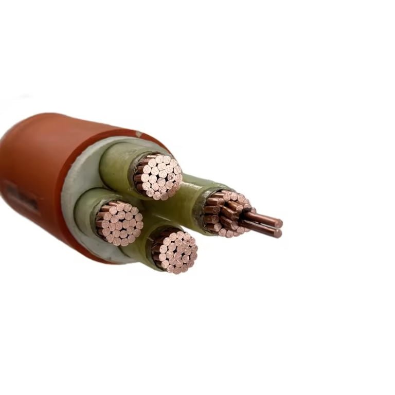
A typical low-voltage steel wire armoured cable is built up in this order:
- Conductor: copper or aluminium, sized for current capacity, voltage drop, fault level, and termination practicality.
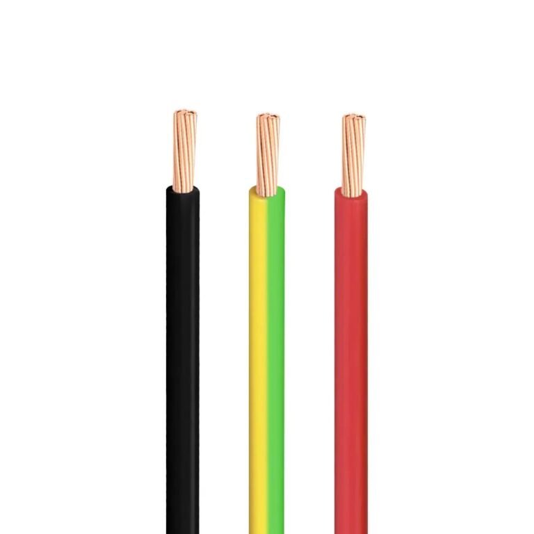
- Insulation: commonly PVC, XLPE, or EPR, depending on thermal rating and specification.
- Bedding or inner sheath: separates the insulated cores from the armour and gives a round, stable base for wire application.
- Galvanized steel wire armour: provides mechanical protection and, where permitted by the design and regulations, may contribute to protective earthing continuity.
- Outer sheath: protects the cable from moisture, abrasion, sunlight, chemicals, fire conditions, or soil environment, depending on compound.
Medium-voltage armoured cable is more layered. It normally includes a conductor screen, insulation screen, metallic screen or tape system depending on design, semi-conductive layers, and tighter dimensional and electrical controls. Those screens are not decorative. They control the electric field, reduce stress concentrations, and make partial discharge behavior predictable. If someone treats a medium-voltage armoured cable as “just a thicker low-voltage SWA,” that is where procurement mistakes become expensive.
Conductor choice is partly electrical and partly mechanical. Copper gives lower resistance for the same cross-section and is easier to terminate in many plants, especially where maintenance teams are used to copper lugs and glands. Aluminium is lighter and often more economical on long feeder runs, but it needs correct lug selection, oxide control, torque discipline, and allowance for larger conductor size. In practice, I worry less about aluminium itself and more about mixed hardware, untrained termination crews, and someone reusing a compression die because “it looks close enough.”
Conductor construction varies by size and standard:
- Solid conductors are usually limited to smaller sizes and fixed installations.
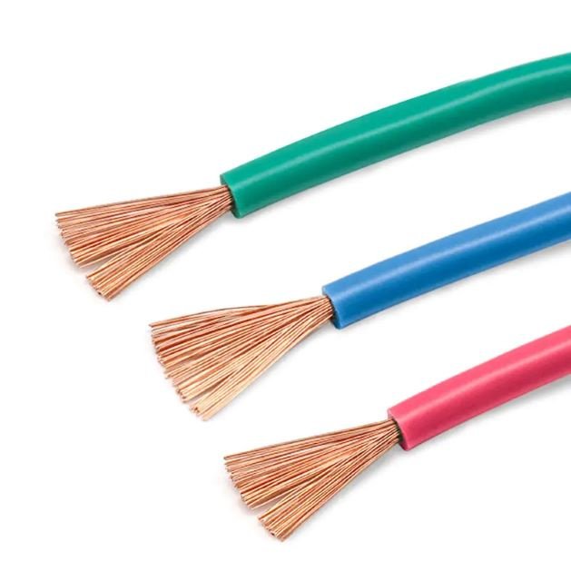
- Stranded conductors improve handling and termination flexibility.
- Compacted stranded conductors reduce overall diameter and can improve gland fit and drum efficiency.
- Circular conductors are common across many sizes and designs.
- Sector-shaped conductors are often used in multicore power cables to reduce overall diameter and improve cable geometry.
Insulation selection changes both performance and purchasing cost. PVC insulation is common in many 0.6/1 kV general-purpose SWA cables and is familiar to installers. XLPE and EPR are used where higher conductor temperature rating, better dielectric behavior, or project specification demands it. As a typical reference, PVC-insulated designs are often associated with 70 °C conductor operation, while XLPE or EPR designs are often associated with 90 °C, subject to the governing standard and compound formulation. The trade-off is not just cable price. A higher thermal rating may reduce conductor size in some conditions, but only if installation grouping, ambient temperature, soil thermal resistivity, and termination ratings also support the calculation.
A 90 °C insulated cable does not automatically allow the whole circuit to operate at 90 °C.True
The allowable operating temperature is limited by the cable standard, insulation compound, accessories, terminals, installation conditions, derating factors, and local code requirements.
Outer sheath material is another area where generic buying causes trouble. PVC is the usual general-duty choice for many industrial and building feeders. PE gives better moisture and abrasion resistance in many buried or exposed applications, but standard PE is not normally chosen for low-smoke building escape routes. LSZH compounds are selected where reduced smoke and halogen emissions matter, such as tunnels, public buildings, transit systems, and enclosed infrastructure. Special sheath compounds may be specified for:
- Oil or hydrocarbon exposure in workshops, refineries, ports, and generator areas.
- UV exposure on tray runs, rooftop routes, and solar-related auxiliary systems.
- Termite or rodent risk in certain buried routes, subject to local practice.
- Cold-weather flexibility where installation or service temperatures are low.
- Chemical exposure near process plants, dosing rooms, or wastewater facilities.
Core configuration must match the earthing system and load profile, not just the equipment nameplate. SWA cable may be single-core, two-core, three-core, four-core, five-core, or multi-core for control and auxiliary circuits. Three-core designs suit many three-phase loads where separate earthing is handled by armour or an external protective conductor, if allowed. Four-core and five-core cables are used where neutral and protective conductor arrangements require them. Nonlinear loads, variable-speed drives, unbalanced single-phase loads, and harmonic currents can change neutral sizing decisions; that needs an electrical design check, not a catalogue guess.
One critical trap is single-core AC cable. Steel wire armour around a single-core AC power cable can suffer magnetic losses and heating because the armour sits in an alternating magnetic field. For single-core AC circuits, aluminium wire armour or another non-magnetic armour system is commonly specified. Trefoil formation, bonding method, screen bonding, circulating currents, and fault current duty all have to be checked together. This is one of those details that looks minor in procurement and then shows up as hot cable armour, derating pain, or failed inspections on site.
For voltage class, many low-voltage SWA building and industrial feeders are rated 0.6/1 kV. Medium-voltage armoured power cables commonly cover classes such as 3.6/6 kV through 18/30 kV, with higher classes specified by project. As voltage rises, screening, semi-conductive layers, partial discharge requirements, voltage withstand testing, and accessory compatibility become much more demanding. Minimum bending radius is also part of the selection conversation; values around 12 to 20 times overall cable diameter are common in many installations, but the actual limit must come from the cable data sheet, standard, and installation method.
Relevant standards often include IEC 60502 for extruded power cables, plus market-specific standards such as BS 5467 for PVC sheathed armoured low-voltage cables, BS 6724 for LSZH low-voltage armoured cables, BS 6622 for medium-voltage PVC sheathed armoured cables, and BS 7835 for medium-voltage LSZH armoured cables. Projects may also require national utility standards, fire authority requirements, railway specifications, marine rules, or owner engineering standards. Always verify the current edition, declared construction, voltage designation, and local acceptance route before placing an international order.
Fire performance labels need careful reading:
- Flame retardant means the cable is designed to resist flame spread under defined test conditions.
- Fire resistant usually means the cable is intended to keep functioning for a specified time under fire test conditions.
- Low smoke addresses smoke emission.
- Zero halogen addresses halogen acid gas emission.
- Circuit integrity relates to continued operation of essential circuits during fire, often with specific cable, support, and installation requirements.
These terms are not interchangeable. A cable can be flame retardant without being fire resistant, and LSZH does not automatically mean circuit integrity.
For international procurement, ask for more than a price and lead time. Factory quality documentation should include routine test records, type test references, inspection reports, drum schedules, conductor resistance results, voltage withstand test results, sheath checks, dimensional records, and traceability documents linking cable drums to production batches. For large projects, drum length planning matters too; a beautiful cable specification still causes field joints if the drum schedule does not match pulling routes, tray access, and crane or forklift limits at site.
Places SWA should be avoided
Standard SWA is a fixed-installation power cable, not a universal answer for every harsh location. Avoid it, or redesign the cable system, where movement, immersion, corrosion, magnetic heating, fire performance, hazardous-area certification, EMC control, or bending space becomes the controlling risk rather than ordinary impact protection.
Movement, vibration, and trailing service
Repeated flexing is one of the fastest ways to make the wrong SWA selection fail. Steel wire armour is strong in the installed position, but it is not built to behave like a flexible carrier cable.
Do not treat standard SWA as the default for:
- Cranes and hoists
- Festoon systems
- Drag chains
- Portable tools
- Trailing leads
- Moving machine axes
- Temporary site equipment that gets dragged, twisted, or recoiled
- Pumps or motors that vibrate continuously without proper cable support
The failure mechanism is simple enough: bending cycles work the bedding, armour layer, insulation, and conductor strands at different radii. Over time, the armour can loosen, the sheath can crack near glands, and the conductor can fatigue where it enters a vibrating terminal box. I have seen good cable blamed for “bad quality” when the real issue was a motor junction box shaking on a soft base with no cleat, no loop control, and a rigid gland taking all the movement.
For moving equipment, look at flexible rubber cable, reeling cable, drag-chain cable, or a manufacturer-approved dynamic cable design. If SWA must feed the fixed side of a moving machine, terminate it on a supported junction box and transition to the correct flexible tail.
Wet, submerged, and chemically aggressive locations
A damp trench is not the same as permanent submersion. Standard SWA may survive normal outdoor exposure when correctly specified and terminated, but deep water, flooded ducts, and submerged pump installations can demand radial and longitudinal water blocking that ordinary construction may not provide.
Risk locations include:
- Submerged borehole and well pumps
- Flood-prone underground ducts
- Quaysides, tunnels, and wet service galleries
- Subsea or river-crossing systems
- Wastewater plants with hydrogen sulfide exposure
- Coastal installations with salt spray
- Fertilizer stores, chemical plants, acid soils, and contaminated ground
Water does not need a dramatic breach to cause trouble. It can track along the conductor interstices, under bedding, or through poorly sealed glands and joints. Once moisture reaches armour, screens, or conductor interfaces, the plant may see rising insulation resistance alarms, corrosion products at terminations, nuisance trips, or a cable that tests acceptably when dry and fails after a wet season.
Corrosion is just as application-specific. Galvanized steel armour has useful mechanical strength, but salt, acids, alkalis, hydrocarbons, and contaminated soils can attack metallic armour or sheath compounds unless the project specifies the right sheath material, oversheath protection, corrosion-resistant armour, ducting, sealing, or cathodic considerations where relevant. Soil resistivity, pH, chloride content, drainage, and backfill quality matter more than catalog wording.
Standard SWA cable is automatically suitable for permanent underwater service.False
Permanent submersion may require water-blocked construction, special sheath materials, pressure-rated design, and tested joints or terminations. Suitability has to be confirmed against the cable design, installation depth, water chemistry, and project standard.
Single-core AC circuits and magnetic heating
Single-core AC power circuits need special care if armour is magnetic. Standard steel wire armour around a single phase can act like an unwanted magnetic path, creating circulating losses and heating that are not present in the same way on multicore cables where the phase currents are grouped together.
For single-core AC feeders, check:
- Whether the armour is non-magnetic, such as aluminum wire armour where permitted
- Trefoil versus flat formation
- Phase spacing and cleat material
- Bonding and earthing arrangement
- Current rating after installation grouping and thermal conditions
- Manufacturer confirmation for the exact voltage, conductor size, and installation method
Do not substitute site habit for calculation on large single-core AC runs; magnetic armour losses can turn a mechanically protected cable into a thermal problem. The trade-off is that steel armour gives robust mechanical protection and familiar gland practice, while non-magnetic or specially designed alternatives may cost more and require different accessories. The preferred choice flips as soon as load current, circuit length, or grouping makes induced heating a credible design constraint.
Fire, hazardous areas, and EMC-sensitive systems
Ordinary PVC-sheathed SWA is often acceptable for general industrial power distribution, but fire-critical circuits are a different design problem. Escape lighting, fire pumps, smoke control, alarms, emergency shutdown systems, and life-safety circuits may need low-smoke zero-halogen performance, circuit integrity under fire, fire-resistant supports, certified glands, and tested installation systems. A fire-rated cable connected through the wrong gland or clipped with plastic ties in the wrong place can fail the intent of the specification.
Hazardous areas are another common trap. In oil, gas, chemical, grain, and dust explosion zones, the cable alone does not make the installation compliant. The complete system may need certified glands, barrier seals, correct ingress protection, sheath compatibility with hydrocarbons, verified armour earthing, bonding continuity, and installation to the applicable hazardous-area standard. Procurement should avoid buying “armoured cable for hazardous area” as a loose description; the zone, gas or dust group, temperature class, gland type, and equipment certification all need to match.
EMC-sensitive circuits also deserve caution. SWA can provide some metallic screening effect, especially at power-frequency interference levels, but it should not be assumed to replace a designed EMC screen. Variable-speed drive motor leads, instrumentation loops, encoder cables, weighing systems, data links, and control circuits may require copper tape screens, braids, symmetrical cores, low-capacitance designs, or segregation from power cables.
Tight bends, dense containment, and better alternatives
Large SWA sizes are stiff, heavy, and unforgiving in tight electrical rooms. Minimum bending radius is often in the range of 12 to 20 times the overall cable diameter, depending on construction and standard, but the actual value must come from the cable datasheet or project specification. Forcing a large SWA around an undersized bend can deform insulation, open the bedding, disturb armour lay, or leave the termination under permanent side load.
Watch for these warning signs during layout review:
- Cable ladder turns drawn tighter than the cable can physically accept
- Glands landing too close to enclosure sidewalls
- Heavy cables entering small panels without cleats or support
- Mixed small control cables and large SWA packed into the same congested tray
- Site teams planning to “make it fit” with extra pulling force
Sometimes the safer and cheaper answer is not bigger SWA. Inside clean electrical rooms, risers, enclosed cable trenches, or dense containment, an unarmoured cable in a protected routing system may be easier to install, easier to terminate, and less likely to damage equipment terminals. SWA earns its keep where mechanical exposure is genuine; where containment already provides the protection, the extra armour can become weight, bend radius, gland cost, and installation labor without much benefit.
Installation details that decide reliability
A correctly specified SWA cable can still fail early if the route, pull, bend, burial, glands, bonding, joints, and tests are treated as site details rather than engineering controls. Most avoidable SWA problems I have seen start at the installation interfaces: trench damage, tight bends, poor glands, wet joints, or unverified armour bonding, not in the untouched middle of the cable drum.
Route planning before final cable lengths are ordered
Route planning should be completed before procurement freezes the cable schedule, because small civil or tray changes can alter drum lengths, joint positions, pulling direction, and gland quantities. A buyer who orders “estimated plus five percent” without checking bend space, trench offsets, and termination access often pays later through extra joints, rework, or awkward pulling setups.
Before issuing the final take-off, check at least these items:
- Trench depth and cover: Direct-burial cover is commonly in the 450 to 1000 mm range, depending on local code, traffic loading, voltage class, and mechanical protection. A road crossing, forklift yard, or future pipe rack zone should not be treated like a soft landscaped area.
- Duct size and fill: Ducts need enough internal diameter for the cable outside diameter, pulling head, lubricant film, and reasonable pulling friction. Long duct runs with several bends are where “it fits on paper” becomes a burnt Saturday for the installation crew.
- Tray and ladder loading: Heavy multi-core SWA can overload light-duty tray quickly. Check tray span, bracket capacity, vertical riser support, and whether future circuits are expected.
- Separation from heat sources: Steam lines, hot process ducts, roof sun exposure, and grouped power circuits all affect current-carrying capacity. Thermal derating is not a paperwork exercise; it decides whether the conductor runs near its insulation temperature limit for years.
- Crossings and segregation: Plan crossings with other power circuits, instrumentation, communications, gas lines, water lines, and drainage before excavation starts. Keep signal cables away from power cable routes unless the design permits the proximity and shielding arrangement.
- Bending space: Confirm bend radius at switchboards, transformer plinths, pits, cable basements, and tray drops. The minimum radius is useless if the wall or gland plate gives the installer only half that space.
- Pulling direction and access: Pull downhill where possible, avoid pulling through the worst bends first, and leave room for drums, jacks, rollers, winches, and pulling socks.
- Joint access: Joints should be placed where they can be made cleanly, inspected, and repaired. Burying a joint under a future concrete slab is a gift to the next maintenance shutdown.
- Future maintenance: Route markers, spare duct capacity, and accessible termination points cost little compared with tracing an undocumented buried feeder after a site expansion.
Pulling control during installation
Pulling control is the practical difference between installing an armoured cable and abusing it into position. The manufacturer’s limits for pulling tension, sidewall pressure, minimum installation temperature, and approved pulling method should govern the job, especially on long underground ducts and vertical risers.
The mechanism is simple enough: pulling tension stretches the cable axially, while bends convert that tension into sidewall pressure against rollers, ducts, or tray edges. If sidewall pressure is too high, the outer sheath can scuff, the armour can be displaced, bedding can be compressed, and insulation geometry can be affected. On medium-voltage cables, that damage may not show up until a withstand test or, worse, after thermal cycling in service.
Control the pull with field discipline:
- Use pulling eyes, stockings, or grips suitable for the cable construction and pulling force.
- Keep roller spacing close enough to prevent dragging, especially near drum stands, bends, and tray transitions.
- Use corner rollers or quadrant blocks rather than letting the cable ride over angle iron or concrete edges.
- Keep winch speed steady and moderate; snatch loading is harder on the cable than a controlled pull.
- Use compatible pulling lubricant in ducts, not grease or whatever is left in the maintenance locker.
- Check cable temperature. PVC and sheath compounds are less forgiving when cold, and installation temperature limits must come from the cable supplier or applicable standard.
- Stop if the cable sheath is shaving, twisting, bird-caging near the pulling grip, or pulling load rises sharply without an obvious reason.
The trade-off is that careful pulling takes more setup time: more rollers, more people watching bends, slower winch speed, maybe a second pull point. That cost is usually lower than replacing a damaged feeder after it has already been buried, glanded, tested, and tied into production equipment.
Bending radius, support, and mechanical handling
Minimum bending radius is not a suggestion for neatness; it protects the cable’s internal geometry. Common allowances are often around 12 to 20 times the overall cable diameter, but the correct value depends on cable construction, voltage class, installation condition, and the manufacturer’s data sheet.
Tight bends can:
- Deform stranded conductors and change how they sit inside the insulation.
- Crack or craze insulation, especially on cold installation days.
- Open the bedding layer under the armour.
- Disturb the lay of the steel wires, creating local pressure points.
- Split, whiten, or stress the outer sheath.
- Increase termination stress where the cable enters a gland plate at an angle.
Tray and ladder work brings its own reliability issues. SWA is rugged, but it is also heavy. Support it at suitable intervals, use saddles or cleats where needed, and protect it from sharp tray edges, cut ladder rungs, and burrs around floor penetrations. Vertical runs need proper cleating so the cable weight is not hanging on the top gland. In grouped tray installations, calculate derating rather than guessing; packed power cables lose heat slowly, and XLPE rated at 90 °C still needs an installation that allows heat to leave the conductor.
Burial practice that survives excavation and weather
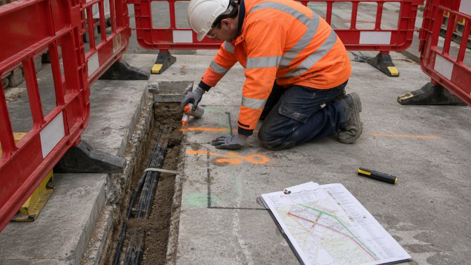
A buried SWA route should be built like a maintainable utility, not just covered before rain arrives. Good trench practice normally includes a prepared bed, clean surround material, warning and protection layers, and accurate records.
For direct burial, specify and inspect:
- Sand bedding or approved fine bedding material below and around the cable.
- Screened backfill near the cable, free from sharp stones, scrap metal, broken bricks, and construction waste.
- Warning tape at the correct depth above the cable.
- Protective tiles, slabs, or covers where excavation risk, shallow cover, or traffic loading justifies them.
- Route markers at direction changes, road crossings, entries to buildings, and long straight sections.
- Extra mechanical protection at roadways, yard crossings, crane areas, and places where future digging is likely.
- As-built drawings with measured offsets from permanent features, not just a red line sketched over an old layout.
Poor compaction can also hurt reliability. If a trench settles, the cable may be left spanning voids, pulled against duct mouths, or sitting in water pockets. Seasonal water tables matter; a route that looks dry in August may behave differently after winter rain or snowmelt.
Glands, terminations, bonding, and joints
Glands are small compared with the cable invoice, but they decide sealing, strain relief, armour continuity, and enclosure ingress protection. Use correctly sized armoured cable glands matched to the cable diameter and armour type, with the right shrouds, locknuts, earth tags, banjo washers, sealing washers, and IP-rated accessories for the location.
Indoor dry plant rooms, outdoor pump stations, coastal sites, chemical areas, and hazardous locations do not need the same termination hardware. Corrosive atmospheres may require plated brass, stainless steel, or other specified materials. Hazardous areas require glands and sealing arrangements certified for the zone and protection concept; this must be verified against current project standards and supplier documentation.
Armour bonding deserves calculation and testing. Do not assume the steel wire armour is automatically an adequate protective conductor for every circuit. Verify continuity through:
- Gland cones and armour clamps.
- Earth tags or banjo washers.
- Bonding jumpers across painted gland plates or removable covers.
- Main and local earth bars.
- Protective device disconnection requirements.
- Test results after installation, not just visual appearance.
Steel wire armour should not be assumed to be a sufficient protective conductor without verification.True
Armour continuity and fault-current capacity depend on cable construction, gland installation, bonding path, circuit protection, and applicable wiring rules. The installer or designer must confirm this by calculation and site testing.
Jointing quality is just as important. Low-voltage joints need proper armour continuity, mechanical protection, and moisture sealing. Medium-voltage joints add stress control, screen treatment, insulation cleanliness, and stricter workmanship requirements. Use approved joint kits for the voltage class and cable construction, and give jointers enough clean working space; a muddy trench wall and a flapping tarpaulin are poor partners for MV cable preparation.
Testing before energization
Testing should prove that installation has not damaged the cable and that the circuit has been identified, connected, and bonded correctly. The exact test regime depends on voltage class, standard, utility or client specification, and equipment connected to the circuit.
Typical pre-energization checks include:
- Visual inspection of sheath condition, bend radius, cleating, tray support, trench protection, glands, and joint locations.
- Conductor continuity tests.
- Armour continuity and bonding checks.
- Insulation resistance testing with suitable test voltage for the circuit.
- Sheath integrity testing where required by the specification.
- Phase identification and phase rotation checks.
- Polarity checks for low-voltage circuits.
- High-voltage withstand or VLF testing where required for medium-voltage cables and permitted by the applicable cable system guidance.
- Verification that test records match cable tags, route drawings, drum numbers, and termination schedules.
The boundary here is important: a passed test does not excuse poor mechanical installation, and a failed test does not automatically prove bad cable manufacture. In practice, the first places to inspect after a bad result are glands, joints, bend points, pulled sections, sheath nicks, and trench areas where backfill or civil work was rushed. Untouched factory cable lengths do fail, but they are not where I would start looking unless the evidence points there.
Procurement data for correct cable
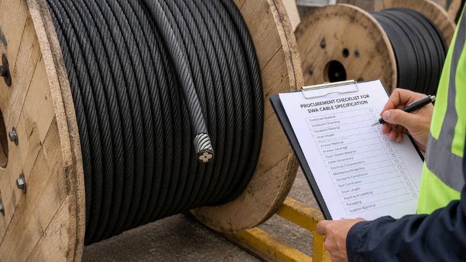
A workable SWA cable enquiry should read like an installation brief, not just a size on a spreadsheet. For quotation, production, testing, and delivery, give the supplier enough data to confirm the electrical design, cable construction, compliance route, packaging, and inspection plan before copper is reserved or extrusion is scheduled.
A purchase order that lists only voltage and conductor size is enough to manufacture correct SWA cable.False
Armour type, insulation, sheath, thermal installation conditions, short-circuit duty, testing standard, packaging, and project documentation can all change the cable design, factory checks, or delivery method.
Electrical duty data
Provide the electrical duty first, because this is where many wrong quotations start. A cable that looks acceptable by ampacity may still fail voltage drop, fault withstand, or protective device coordination once the route length and starting load are known.
Include:
- Rated voltage
- Low-voltage SWA is commonly specified at 0.6/1 kV.
- Medium-voltage armoured power cable often falls in ranges such as 3.6/6 kV to 18/30 kV, with higher classes defined by project specification.
- State phase-to-phase and phase-to-earth voltage where the system is not conventional.
- System type
- AC or DC service.
- Frequency, usually 50 Hz or 60 Hz.
- Single-phase, three-phase three-wire, three-phase four-wire, or DC positive/negative configuration.
- Load and starting data
- Full-load current.
- Continuous, intermittent, cyclic, or emergency duty.
- Motor starting current and starting duration, especially for pumps, compressors, crushers, and long conveyor drives.
- Harmonic content if variable-speed drives, UPS systems, rectifiers, or large nonlinear loads are involved.
- Fault and protection data
- Prospective short-circuit current.
- Required short-circuit duration, often linked to relay clearing time.
- Earthing system: TN-S, TN-C-S, TT, IT, resistance-earthed, solidly earthed, or another project arrangement.
- Protective device type and setting: fuse, MCCB, ACB, relay, recloser, differential protection.
- Whether armour may be used as a protective earth, a supplementary earth, or not relied upon for earthing. This must be checked against local rules and fault loop requirements.
- Voltage drop limit
- Maximum allowable voltage drop during normal running.
- Separate starting voltage drop limit if motors are sensitive or if the utility imposes flicker limits.
The mechanism is straightforward: current sets conductor heating, route length drives voltage drop, and fault level determines whether the conductor, screen, armour, and protective path survive until the protection clears. Oversizing solves some of this, but it raises purchase cost, drum weight, pulling load, gland size, and tray loading. The preferred choice flips when installation labor and outage risk cost more than the extra conductor metal.
Cable size and construction details
State the required construction instead of assuming the supplier will choose the same convention your last project used.
Specify:
- Conductor material: copper or aluminium.
- Cross-sectional area for each conductor.
- Conductor class if flexibility matters, such as stranded compacted conductors versus more flexible classes.
- Number of cores: 2, 3, 4, 5, or single-core arrangement.
- Neutral size: full neutral, reduced neutral, or no neutral.
- Protective conductor requirement: separate core, armour as CPC where allowed, or external earth conductor.
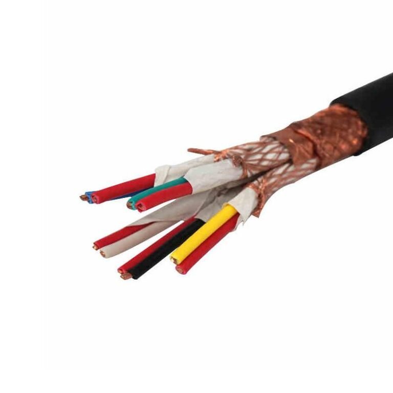
- Screen requirement: no screen, copper tape screen, copper wire screen, metallic screen for MV, or project-specific shielding.
- Armour type:
- Steel wire armour for many multicore fixed installations.
- Steel tape armour where specified by local practice.
- Non-magnetic armour, often aluminium wire, may be required for single-core AC circuits to avoid heating from induced currents.
- Insulation material:
- PVC, commonly associated with 70 °C conductor temperature ratings depending on compound and standard.
- XLPE or EPR, commonly associated with 90 °C ratings, again subject to the actual standard and compound.
- Outer sheath:
- PVC for general duty.
- PE or MDPE where moisture resistance and abrasion matter.
- LSZH or low-smoke halogen-free sheath where smoke and acid gas limits are required.
- Oil-resistant, flame-retardant, UV-resistant, anti-termite, or special compound where the environment demands it.
Do not mix construction terms loosely. “Armoured XLPE cable” is not enough for a factory to lock the bill of materials, especially on export projects where gland compatibility, sheath color, marking language, and standard marking format may be checked at receiving inspection.
Installation and derating conditions
The installation method changes current rating as much as the conductor size does. Heat leaves a cable differently in free air, buried soil, duct bank, tray grouping, or a hot riser next to other feeders.
Send the supplier or design reviewer:
| Installation data | Why it matters |
|---|---|
| Direct burial, duct, tray, ladder, tunnel, conduit, riser, or open air | Determines thermal model, mechanical protection need, and installation accessories |
| Ambient air temperature | Higher ambient reduces allowable current |
| Soil thermal resistivity | Dry sand, wet clay, and backfill have very different heat dissipation |
| Burial depth | Common direct-burial cover may be roughly 450 to 1000 mm, but local code, traffic loading, and protection method decide the actual value |
| Grouping and spacing | Closely grouped circuits derate heavily, especially in ducts |
| Outdoor exposure | Drives UV sheath requirements, water sealing, and drum storage planning |
| Pulling route | Bends, rollers, winch points, and sidewall pressure can decide whether a proposed drum length is installable |
Minimum bending radius is often in the range of 12 to 20 times the overall cable diameter, depending on construction and installation condition, but the current cable datasheet and project standard should control. On site, this is not academic: a cable forced around a tight tray corner may pass continuity testing and still carry damaged insulation or a distorted armour bed into service.
Environmental and service exposure
List the exposure conditions plainly. Procurement teams sometimes hide these in a civil drawing note, and the cable supplier never sees them.
Check for:
- UV exposure on roofs, pipe racks, solar farms, quays, and outdoor substations.
- Standing water, intermittent flooding, wet ducts, or high groundwater.
- Hydrocarbon contact, cutting oil, transformer oil, solvents, acids, alkalis, fertilizer, or wastewater chemicals.
- Rodents, termites, ants, or other biological attack.
- Salt spray in coastal plants, ports, offshore support areas, and desalination sites.
- Low-temperature installation or operation, where sheath cracking risk increases.
- High-temperature zones near boilers, furnaces, dryers, engine rooms, or process pipework.
- Fire performance requirements: flame retardance, fire resistance, circuit integrity, low smoke, halogen-free, or low toxicity.
- Mechanical impact risk from forklifts, dropped tools, scrap handling, rock backfill, or maintenance traffic.
A good supplier can propose compound and armour options, but only if the exposure is known before production. After delivery, changing from standard PVC to LSZH, anti-termite, or oil-resistant sheath is not a paperwork change; it is a different cable.
Applicable standards and approvals
Name the controlling standard and the project specification. If there is a conflict, say which document takes precedence.
Typical references may include:
- IEC cable standards, such as IEC 60502 series for many extruded insulated power cable applications.
- British Standards, such as BS 5467 or BS 6724 where applicable to the required construction.
- European requirements, including CPR-related fire classification where the cable is placed on the EU market and building rules apply.
- National utility specifications.
- Mining, railway, oil and gas, marine, airport, or industrial client specifications.
- Project-specific test clauses, marking rules, color codes, sheath thickness requirements, and inspection hold points.
Do not write only “IEC standard” unless the design is genuinely open. Quote the standard number, edition if specified, voltage class, construction table, and any special test clauses available from the project documents. This avoids the painful late-stage argument where the factory made a compliant cable, but not the one the client specification intended.
Length, drums, and export packaging
Cable length is a manufacturing and logistics decision, not just a delivery note. Long drums reduce jointing, but they increase drum weight, handling difficulty, pulling tension, and container planning.
Confirm:
- Drum length for each size.
- Length tolerance, such as exact cut length or acceptable production tolerance.
- Maximum gross drum weight allowed at site.
- Drum flange diameter and barrel diameter limits.
- Container loading requirement and destination handling limits.
- Pulling direction and whether the inner or outer cable end must be accessible.
- Drum marking: project name, cable tag, size, voltage, length, net/gross weight, rotation arrow, purchase order, and destination.
- Cable end sealing: heat-shrink caps, pulling eyes, moisture protection, and extra sealing for MV cable where required.
- Storage conditions before installation, especially outdoor storage duration, stacking limits, and protection from standing water.
For international bulk orders, I prefer a drum schedule reviewed by engineering, logistics, and site construction together. A “perfect” 900 m drum is not perfect if the site crane limit is lower than the drum weight or if the cable has to pass through a basement access hatch.
Documentation and inspection package
Agree the document package before the purchase order is released.
Common requirements include:
- Technical datasheet.
- Cable construction drawing.
- Routine test report.
- Type test certificate, where applicable and available for the design family.
- Material declaration.
- Quality certificate or certificate of conformity.
- Inspection and test plan.
- Packing list.
- Certificate of origin, if needed for customs or project finance.
- Drum schedule and shipping marks.
- Installation guidance or handling instructions where required.
Inspection requirements should be just as clear:
- Third-party inspection agency, if any.
- Witness testing requirements.
- Sample approval before mass production.
- Production hold points.
- Pre-shipment inspection.
- Photo documentation of cable marking, drum marking, end sealing, packing, and container loading.
Witness testing sounds simple until the inspector arrives after the test has already been completed. Put hold points and notice periods in writing, including who releases production, who accepts test reports, and who can approve deviations.
Commercial and project coordination requirements
For global projects, the correct cable is not only a product code; it is a coordinated supply package involving engineering review, manufacturing capacity, testing consistency, export logistics, and post-delivery technical support. This is where supplier capability matters, especially when one purchase order covers many cable sizes, mixed voltage classes, and staged site deliveries.
Clarify:
- Required delivery schedule and latest acceptable shipment date.
- Partial shipment plan by cable tag, work area, or installation sequence.
- Incoterms and named place.
- Spare length philosophy: percentage spare, spare drums, or replacement strategy by critical feeder.
- Warranty expectations and defect handling process.
- After-sales technical support requirements.
- Technical clarification workflow: who answers design questions, who approves deviations, and how revisions are controlled.
For a manufacturer such as Shandong Jinda Special Cable Group, with multiple production bases, large manufacturing space, export experience across many countries, and an integrated system covering R&D, production, sales, technical support, and after-sales service, the buyer should use that capability by submitting a complete enquiry package early. The cleaner the procurement data, the less risk there is of receiving a cable that is electrically adequate but wrong for the installation, inspection regime, or delivery sequence.
This checklist stops being enough when the route is safety-critical, fire-rated, classified hazardous, railway/mining governed, subsea, nuclear, or controlled by a utility standard with mandatory design approval. In those cases, the cable schedule should go through formal engineering review before quotation is frozen, not after the first drum is already on the water.
Frequently asked questions
Can SWA cable be buried directly in the ground?
Yes, provided the cable construction, voltage rating, sheath material, burial depth, and local installation code all permit direct burial. In practice, I would still use sand bedding or screened backfill where the trench has stones, demolition waste, sharp aggregate, or compacted hardcore; armour is not a magic sleeve against point loading.
Use extra protection when the route has foreseeable disturbance:
- Ducts under roads, gateways, concrete slabs, rail crossings, or areas likely to be excavated again.
- Sand bedding and selected backfill where native soil can cut or deform the outer sheath.
- Cable tiles, marker boards, or mechanical covers where digging risk is high.
- Warning tape above the cable route so the excavator operator gets a second chance before finding the cable with a bucket tooth.
Common burial cover is often somewhere around 450 to 1000 mm, but that number depends on local code, traffic loading, soil condition, and mechanical protection.
Is SWA cable waterproof?
Standard SWA is weather-resistant, not automatically waterproof in the sense of long-term submerged or water-pressure service. The weak points are usually joints, glands, sheath damage, and water migration along conductor interstices after a nicked sheath or poor termination.
For wet ground, pits, tunnels, ports, wastewater plants, or flood-prone sites, specify the detail rather than just saying “waterproof”:
- Water-blocked conductor or core construction where longitudinal water migration is a concern.
- Suitable outer sheath, such as PE, HDPE, MDPE, or special compounds where PVC is not enough.
- Correct resin, heat-shrink, cold-shrink, or mechanical joints rated for the environment.
- Outdoor glands with proper seals, shrouds where appropriate, and corrosion-resistant hardware.
- Inspection access, because buried joints are where maintenance teams usually lose the argument.
Can steel wire armour be used as the earth conductor?
Sometimes, but only after calculation and verification. The armour must have adequate cross-sectional equivalent, fault current withstand, earth fault loop impedance, and reliable continuity through glands, joints, banjos, earth tags, or bonding conductors.
Do not assume “armoured” means “acceptable CPC.” The design should check:
- Prospective earth fault current and disconnection time.
- Armour resistance and reactance for the installed length.
- Adiabatic thermal withstand during fault conditions.
- Continuity through every termination and joint.
- Test results after installation, not just catalogue data.
Many engineers still add a separate protective conductor on critical circuits because it simplifies verification and reduces dependence on termination quality.
What is the difference between SWA cable and unarmoured power cable?
SWA costs more, weighs more, bends less easily, and takes longer to gland and terminate. In return, it gives much better mechanical protection for fixed installations exposed to impact, compression, rodent risk, site traffic, and rough handling during installation.
Unarmoured cable is usually better in clean cable trays, panels, machines, and protected indoor routes where flexibility, pulling ease, and termination speed matter more than abuse resistance. SWA earns its keep where replacement would mean digging, shutdown, or arguing with civil contractors about who damaged the feeder.
Can SWA cable be used outdoors?
Yes, if the sheath, glands, supports, and termination boxes are suitable for sunlight, rain, temperature cycling, and local pollution. Standard PVC sheaths are common, but UV exposure, cold bending, oil, chemicals, or coastal air may push the specification toward UV-stabilized PVC, PE, LSZH, or other project-specific compounds.
Watch outdoor supports as much as the cable itself. A cable tied hard to hot steelwork, sagging between trays, or rubbing on a bracket edge can fail earlier than the same cable laid neatly in a trench.
Why is standard steel wire armour not normally used around single-core AC power cables?
Single-core AC cables create an alternating magnetic field around each conductor. If that field links with magnetic steel armour, it can induce circulating currents and magnetic losses, causing unwanted heating and energy loss.
For single-core AC power circuits, non-magnetic armour such as aluminium wire armour is commonly considered, or the cable system is designed using unarmoured single cores with suitable containment and earthing. The correct answer depends on current, spacing, installation formation, fault level, and the applicable cable standard.
What cable gland type is required for SWA cable?
Use an armoured cable gland that matches the cable diameter, armour size, sheath material, ingress protection requirement, and installation environment. Indoor dry locations may use a simpler armoured gland, while outdoor, wet, dusty, corrosive, or hazardous areas normally need sealed glands with the correct IP and certification.
Gland sizing matters because the armour wires must be gripped evenly. A loose gland gives poor bonding and water entry; an over-tightened one can cut the sheath, distort the armour, or crack a small enclosure wall. Bonding accessories are not decorative parts — the earth path often depends on them.
How long does SWA cable last in service?
A correctly selected and installed SWA cable can last for decades; 25 to 40 years is not unusual in stable fixed installations. Life is shortened by overload, high ambient temperature, poor heat dissipation, water ingress, sheath cuts, chemical attack, UV degradation, repeated movement, bad glands, and overloaded joints.
Thermal ageing is the quiet killer. PVC insulation is commonly rated around 70 °C conductor temperature, while XLPE or EPR is commonly around 90 °C, subject to the standard and compound. Running near those limits all year is a different duty from an occasional peak.
Can SWA cable be used for solar, wind, battery storage, or generator projects?
Yes, SWA is often suitable for fixed AC power circuits in renewable and backup power projects, especially for buried runs, inverter outputs, auxiliary supplies, transformer connections, and generator feeders. DC solar string cable is a different product category and should not be replaced casually with ordinary SWA unless the voltage, polarity, UV, temperature, and standard requirements are explicitly satisfied.
For battery energy storage and generators, pay close attention to fault current, short-circuit duration, earthing method, fire performance, and cable routing near fuel, ventilation openings, or container edges.
What information should be sent for an accurate SWA cable quotation?
Send the manufacturer enough data to build the cable, not just guess the nearest catalogue line:
- Voltage rating, such as 0.6/1 kV or medium-voltage class.
- Number of cores and conductor size.
- Conductor material, usually copper or aluminium.
- Insulation type, such as PVC, XLPE, or EPR.
- Armour requirement and whether single-core AC service is involved.
- Outer sheath material, colour, UV, flame, oil, chemical, or LSZH requirements.
- Installation method: buried, duct, tray, tunnel, indoor, outdoor, marine, industrial, or hazardous area.
- Approximate route length, drum length preference, and delivery schedule.
- Applicable standard, project specification, test requirements, and destination country.
- Any special packing, marking, documentation, or third-party inspection requirement.
Verify the cable duty before ordering
Choose steel wire armoured cable when a fixed power circuit needs a tough mechanical barrier against burial loads, impact, abrasion, rodents, outdoor exposure, or industrial routing hazards. Do not treat “SWA” as a complete specification; it is only one part of the cable construction, and the duty has to be checked before a buyer compares prices.

Before purchase, lock down the engineering data that decides whether the cable will run cool, trip correctly, survive the route, and pass inspection:
- Voltage class: common low-voltage SWA is often 0.6/1 kV, while medium-voltage armoured power cables may be specified from 3.6/6 kV up to 18/30 kV or higher by project requirement.
- Load current and derating: conductor size depends on load, grouping, ambient temperature, soil thermal resistivity, tray spacing, duct fill, and whether the cable is in air, duct, trench, or direct burial.
- Short-circuit duty: the conductor and armour/earth path must withstand fault current for the protection clearing time. A cable that is acceptable for steady load may still be undersized for fault energy.
- Voltage drop: long site feeders, pump circuits, lighting runs, and remote buildings can fail on voltage drop before they fail on ampacity.
- Installation method: direct burial, duct, ladder tray, wall fixing, riser, and exposed yard routing all change mechanical risk and thermal performance.
- Temperature rating: PVC insulation is commonly rated around 70 °C, while XLPE or EPR designs are often 90 °C, subject to the actual standard and compound.
- Sheath environment: oils, sunlight, chemicals, standing water, termite risk, and cold-weather handling can push the project toward a different outer sheath or barrier design.
- Fire performance: tunnels, substations, public buildings, hospitals, high-rise plant rooms, and escape routes may require LSZH, flame-retardant, or fire-resistant cable designs.
- Earthing design: confirm whether the armour is part of the protective earth path, whether a separate CPC is required, and how glands, banjos, earth tags, and terminations will be tested.
- Local standard and inspection requirement: IEC, BS, national utility standards, project specifications, and third-party test documentation must be agreed before manufacturing.
Change the specification when the circuit or environment stops matching standard multicore SWA assumptions. Single-core AC circuits may need non-magnetic armour such as aluminium wire armour to avoid circulating losses and heating. Wet routes, flood-prone trenches, and long underground pulls may justify water-blocked construction rather than relying on a standard sheath alone. Fire-critical areas may need LSZH or fire-resistant cable. Moving equipment should not be fed with ordinary SWA just because it looks strong; use a flexible cable designed for repeated bending, torsion, and reel or festoon duty.
Price-only buying is where many cable problems start. Two offers can both say “SWA cable” while differing in conductor material, insulation compound, armour type, sheath grade, test scope, packing, certification, and drum length. A slightly cheaper drum that forces extra joints, fails a documentation check, or arrives with the wrong sheath for the route is not cheaper once installation labor and outage risk are counted.
Project buyers can send Shandong Jinda Special Cable Group Co., Ltd. the load schedule, route conditions, installation method, applicable standard, required lengths, drum limits, and documentation requirements for technical review, manufacturing confirmation, and a project quotation. For bulk SWA cable orders, verify the duty, confirm the standard, and request a cable construction that matches the actual installation environment before placing the purchase order.