A buried SWA cable that is too shallow is easy to strike with a fence post, drainage bucket, or later civil works; one that is buried blindly deep can create avoidable excavation cost, awkward jointing, and thermal assumptions nobody checked. The operational result is usually nuisance trips, damaged sheath, failed inspection, or an outage in the worst possible weather. The practical answer is not “dig deeper”; it is to match burial depth, bedding, warning tape, route records, and mechanical protection to the actual ground risk.
Most low-voltage SWA cables are buried roughly 450 mm to 1000 mm deep, with the final depth set by local regulations, traffic loading, soil conditions, and mechanical protection. Domestic paths may sit near the lower end; roads, yards, and disturbed ground usually need deeper burial or ducted protection.
The messy part is that burial depth is only one layer of the installation decision. A cable laid at a sensible depth in screened bedding, with selected backfill and warning tape 150 mm to 300 mm above it, is a different risk from the same cable thrown into rubble at the same measured depth. That is where good site practice, project specification, and procurement discipline start to matter.
Common burial depth ranges
For low-voltage SWA cable, a practical buried-depth framework normally starts around 450 mm in low-disturbance private ground and moves toward 1000 mm or more where traffic, excavation, agriculture, or public utility coordination is expected. Treat these figures as working ranges for early design and estimating only; the project specification, local wiring rules, utility owner requirements, and any permit conditions take priority every time.
A useful way to think about depth is not “how deep can we afford to dig?” but “what future activity is most likely to reach this cable?” The armour helps the cable survive mechanical abuse, but it is not a licence to bury it casually. A pickaxe, post auger, drainage trencher, or resurfacing planer can still create a dangerous situation if the route is shallow, unmarked, or poorly recorded.
| Site condition | Common practical depth range | Why this depth is often selected |
|---|---|---|
| Domestic gardens and low-disturbance landscaping | About 450 mm, subject to local rules | Moderate digging risk, manageable route control, lower traffic load |
| Residential driveways, footpaths, light commercial areas | Around 600 mm | Light vehicles, paving repairs, posts, drains, future utility work |
| Road crossings, industrial yards, logistics areas, hardstanding | Roughly 750 mm to 1000 mm | Heavy vehicles, reinstatement work, forklifts, excavators, civil maintenance |
| Agricultural land and open ground | Often 900 mm to 1200 mm | Ploughing, subsoiling, drainage, irrigation, fencing, seasonal ground work |
| Public utility corridors and multi-service routes | Project-specific | Separation from other services and safe access for future maintenance |
| High-voltage, critical, or special-risk circuits | Project-specific, often with ducts or concrete protection | Network rules, thermal design, route security, client standards |
A low-voltage SWA cable is commonly buried between about 450 mm and 1000 mm, depending on route risk, traffic load, soil conditions, and local regulations.True
This is a typical industry planning range, not a universal legal requirement. The installed depth must be checked against the current project specification, applicable local code, utility requirements, and site risk assessment.
Domestic gardens and low-disturbance landscaped areas
About 450 mm is commonly used in gardens and controlled landscaped areas because the likely future disturbance is usually hand digging, planting, edging, or shallow irrigation work rather than heavy excavation. That depth gives some practical separation from normal gardening activity while keeping trenching cost and reinstatement under control.
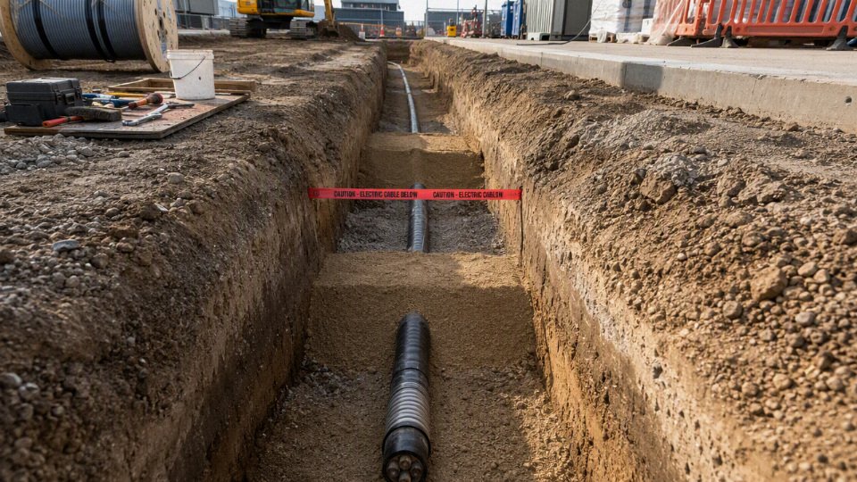
This is the kind of route where the installation quality matters as much as the number on the tape measure. A typical build-up would include screened bedding, the SWA cable or duct, selected backfill, warning tape roughly 150 mm to 300 mm above the cable, and permanent route records. If the route is straight, recorded on an as-built drawing, and avoids obvious future planting beds, 450 mm can be a sensible design starting point.
The boundary is local practice and exposure. In some jurisdictions or client specifications, a shallower private-garden run may be rejected unless it is in suitable ducting, under slabs, covered with additional mechanical protection, or installed by an approved method. I have seen small private jobs where the trench depth looked acceptable on paper, but the cable crossed exactly where a future gate post was likely to be drilled. That is poor routing, not just a depth issue.
Residential driveways, footpaths, and light commercial areas
Around 600 mm is often selected where people drive, park, resurface, install fences, modify drains, or bring in small plant later. The extra cover gives a more forgiving installation when the surface is no longer just soil and shrubs but block paving, concrete edges, gullies, kerbs, and occasional maintenance work.
The mechanism is simple: surface use changes the kind of damage the cable may face. A garden fork tends to be shallow and visible. A fence post auger, mini-excavator bucket, or saw-cut-and-breakout repair can reach deeper, and the operator may be working from a vague sketch rather than the original cable route drawing. Driveways also settle, crack, and get resurfaced. A contractor taking out 150 mm of old base and installing a new drain channel can get close to services that were installed too shallow.
There is a cost trade-off here. Moving from 450 mm to 600 mm adds excavation time, spoil handling, and reinstatement effort, particularly in compacted sub-base or narrow access. For a short domestic supply that may be a small cost. For a long perimeter lighting run around a commercial site, it becomes material. The preferred choice flips toward deeper installation when the owner cannot tightly control future works or when the area has a history of changes: new gates, EV chargers, CCTV poles, drainage repairs, or telecoms upgrades.
Road crossings, industrial yards, logistics sites, and hardstanding
For road crossings, loading yards, forklift routes, and hardstanding, 750 mm to 1000 mm is often specified because the risk is no longer just accidental hand digging. These areas see heavy loads, concrete cutting, pavement reconstruction, dock-leveller work, drainage trenching, bollard installation, and civil excavation with machines that can damage a service before anyone has time to react.
In an industrial yard, I would usually be more interested in the whole protection system than in depth alone. Duct selection, bedding, marker tape, route markers, draw pits, spare ducts, minimum bend radius, and thermal environment all affect whether the installation remains serviceable. A cable buried deep in crushed rubble with no reliable route record is not a good installation. A ducted route with proper bedding, clear marker tape, accurate records, and accessible pits is usually easier to own for the next 20 years.
Hardstanding also brings a thermal question that is easy to overlook. Cable current rating depends partly on how heat leaves the conductor through insulation, bedding, soil, duct wall, and surrounding ground. If a designer assumes one soil thermal resistivity but the installation ends up in dry sand, congested ducts, or under heat-retaining pavement, the safe current-carrying capacity may not match the catalogue assumption. Deeper burial can place the cable in more stable ground temperature, but it can also make heat dissipation calculations less straightforward if the route is ducted, grouped, or passing through poor backfill.
Agricultural land and open ground
Agricultural routes often need greater depth, commonly moving toward 900 mm to 1200 mm depending on farming practice, because the future hazard is not occasional gardening but deliberate ground penetration. Ploughing, subsoiling, mole drainage, land drainage repairs, irrigation pipework, trenching, fence posts, and hedge work can all reach cable depth if the route is not designed around the way the land is actually used.
The right question for the farmer or land manager is not just “how deep do you plough?” Ask about:
- Maximum ploughing and subsoiling depth, including rented contractors’ equipment
- Existing and planned field drainage runs
- Irrigation mains, hydrants, and seasonal pipe movement
- Fence, gate, and stock-water installation plans
- Whether the field may change crop type or cultivation method
- Access routes for tractors, harvesters, and ditch maintenance plant
The design may also need marker posts, easement drawings, GPS route records, and a clear restriction on deep cultivation over the cable corridor. Depth alone does not protect a cable from a contractor who does not know it exists.
Public utility corridors and multi-service routes
In public corridors, burial depth is coordinated, not guessed. The cable has to sit in a route that respects water, gas, telecoms, drainage, district heating, street lighting, and other electrical services while still allowing each asset to be found, maintained, and repaired safely.
This is where generic depth tables become dangerous if used without coordination. A water main may need frost cover. Drainage needs fall. Gas and telecoms may already occupy the most convenient alignment. Existing drawings may be inaccurate by enough to matter; older sites often have abandoned ducts and unrecorded repairs. Trial holes, cable avoidance tools, ground-penetrating radar where appropriate, and utility owner consultation are part of the job, not paperwork theatre.
Separation can be horizontal, vertical, or both, depending on the service and the governing rules. The final SWA depth may be driven by crossing details, minimum clearances, access chambers, or the need to avoid putting one maintainable service directly under another. A neatly buried cable that prevents safe repair of a gas pipe later is still a bad design.
High-voltage, critical supply, or special-risk circuits
For high-voltage, critical supply, or special-risk circuits, burial depth is often determined by owner standards, network operator rules, duct bank design, concrete protection, thermal modelling, route security, and outage consequence rather than by a simple SWA convention. The higher the consequence of failure, the less acceptable it is to rely on “normal depth” as the main control.
Examples include:
- Main incomers to factories or data halls
- Fire pump, life-safety, or emergency power circuits
- Network distribution feeders
- Export cables from generators or battery systems
- Routes crossing public roads, rail interfaces, ports, or secure sites
- Circuits installed in grouped duct banks where thermal derating is significant
Here the trade-off can cut both ways. A deeper route may reduce accidental strike risk and improve security, but it can also increase excavation cost, extend outage repair time, require larger pits, complicate pulling tensions, and make fault location and jointing more difficult. If the cable is in ducts surrounded by concrete, the mechanical protection improves, but the thermal design and installation pulling plan need proper checking.
Deeper is not automatically better. Once cover is enough for the credible damage sources, the next gains often come from better routing, duct specification, warning systems, accurate records, and controlled future work permits. The depth number should be treated as one layer in a protection strategy, not the whole strategy.
Rules and standards
Buried SWA cable rules should be treated as a compliance framework, not as a single number copied from another project. In many jurisdictions, the controlling principle is that the cable must be deep enough, marked well enough, and mechanically protected enough to survive reasonably foreseeable ground activity at that location.
That phrase “reasonably foreseeable” matters on site. It includes the obvious work, such as later excavation with a mini-digger, but also the ordinary messy jobs that happen after handover:
- fence post installation along a boundary;
- landscaping, tree planting, and irrigation trenching;
- drain repairs and shallow duct additions;
- resurfacing or saw-cutting in yards;
- forklift impact damage at inspection pits or kerb edges;
- road planing, verge works, and utility crossings;
- temporary site cabins, scaffold bases, and ground anchors.
A cable under a private flower bed and a cable crossing an industrial loading yard are not exposed to the same risk, even if both are low-voltage SWA. The standard may use similar words for both, but the engineering answer will not be the same.
There is one universal legal burial depth for all SWA cable installations.False
Burial depth is set by the applicable national or local rules, route risk, mechanical protection, land use, and project specification. Some codes give prescriptive cover values; others require suitable protection against foreseeable damage rather than one fixed number.
Which rules normally control an SWA burial design?
The applicable rule set is usually layered. The mistake I see in procurement packages is that somebody writes “install to standard” without saying which standard, which country, which authority, or which site condition. That leaves the installer, cable supplier, and inspector arguing after the trench is already open.
Typical control documents include:
- National wiring regulations: These define electrical safety expectations, wiring methods, protection against mechanical damage, earthing and bonding, inspection, testing, and identification. Some are based on IEC practice, while others use their own prescriptive tables and terminology.
- Local electrical codes: City, state, provincial, or municipal rules may amend the national position. Do not assume a project in one region of a country is accepted the same way in another.
- Utility requirements: If the cable interfaces with a utility supply, substation, metering point, or service corridor, the utility may impose trench profiles, separation distances, marker systems, duct colors, or inspection hold points.
- Building control and permitting rules: Commercial buildings, public facilities, and residential developments may need drawings and inspection evidence before trenches are closed.
- Highway or road authority specifications: Road crossings and public footpaths are rarely just an electrical issue. Cover depth, reinstatement, duct class, traffic management, and compaction testing may all be controlled by the highway authority.
- Mining, oil and gas, petrochemical, or hazardous-area rules: These sites often add requirements for cable type, sheath material, impact protection, chemical resistance, fire performance, segregation, and traceability.
- Client engineering standards: Large industrial buyers, utilities, airports, rail operators, data centers, and energy companies often have internal standards that exceed legal minimums.
A job can satisfy the legal minimum and still be rejected commercially if it does not meet the buyer’s project specification. That is not bureaucracy; it is how asset owners control maintainability, future excavation risk, insurance exposure, and spare-part consistency across a plant.

Fixed-depth rules versus risk-based rules
Some jurisdictions use prescriptive burial cover tables for certain wiring methods and locations. Others use performance wording: protect against mechanical damage, install at a suitable depth, provide warning and route identification, and select a cable system appropriate for the environment. Both approaches can be valid, but they behave differently during design review.
Where a code gives a table, the designer still has to check the assumptions behind it:
- Is the route under soil, concrete, a road, a paved yard, or public land?
- Is the cable direct-buried, in duct, in a concrete trough, or under slabs?
- Is the circuit low voltage, control, instrumentation, or higher voltage distribution?
- Is the location subject to vehicle loading, future excavation, chemical exposure, or flooding?
- Are separation distances required from gas, water, telecoms, drainage, or other power circuits?
Where the code does not give one fixed SWA depth, the design basis becomes more important, not less. The selected depth and protection method should be written down, not left as a verbal site decision. A reasonable note might say that the cable is installed in screened bedding, at a stated cover depth, with tiles or duct where crossing trafficked areas, warning tape 150 mm to 300 mm above the cable, and route coordinates captured before backfill. That type of record gives the inspector and future maintenance team something to verify.
The trade-off is straightforward. Deeper burial gives better protection against casual excavation and surface disturbance, but it increases trenching cost, spoil handling, dewatering risk, bend management at risers, repair time, and the chance of clashing with drainage or other services. Shallower burial can be acceptable where rules allow it and robust mechanical protection is used, but it demands better documentation and stricter control of future ground works. The preferred choice flips when civil constraints, water table, rock, contaminated soil, or existing utilities make depth less reliable than engineered protection.
Compliance, good practice, and buyer specifications are not the same thing
Regulatory compliance is the minimum legal gate. Engineering good practice is what keeps the installation maintainable and safe after several years of plant changes. Client specifications are the commercial contract requirements, and they can be tougher than either.
For example, a local code may permit a certain buried wiring method, but a food factory may still require ducted routes for washdown areas and easier replacement. A port operator may insist on heavier mechanical protection in container-handling zones. A data center buyer may require specific sheath performance, fire documentation, drum traceability, and as-built survey records before accepting delivery. None of that is unusual.
Professional projects usually expect a document set that includes:
- Cable route drawings showing origin, destination, route, joint positions if any, and crossing details.
- Trench cross-section details covering cover depth, bedding material, cable spacing, ducts, tiles, slabs, warning tape, and backfill.
- Installation method statements explaining excavation, cable pulling, bend radius control, drum handling, bedding, backfilling, and reinstatement.
- Inspection and test plans with hold points before backfill, insulation resistance testing, continuity checks, sheath inspection, and earthing or armour bonding verification as applicable.
- As-built records showing final route changes, depth evidence, coordinates, and photographs before the trench is closed.
- Cable documentation such as test certificates, drum numbers, voltage rating, conductor size, armour type, sheath material, fire performance where applicable, and compliance with the project specification.
Photographs before backfilling are cheap insurance. I prefer them with a tape measure visible, not just a close-up of a cable in a trench that could be anywhere. On larger sites, geotagged photos and marked-up drawings save a lot of argument when somebody excavates near the route five years later.
When approval or specialist design input is needed
A qualified electrical designer should be involved whenever the installation affects protection coordination, voltage drop, fault level, earthing, armour bonding, or hazardous-area classification. A civil engineer should be involved where the trench passes through roads, structural slabs, retaining areas, high-load yards, made ground, poor drainage, or heavily compacted industrial surfaces.
Local authority, utility, or client approval is commonly needed for:
- road crossings and public footpaths;
- public land, easements, or shared service corridors;
- export projects where the buyer, installer, and end user work under different national codes;
- hazardous areas, fuel storage, mining, chemical plants, and marine terminals;
- high-load industrial routes with cranes, reach stackers, heavy forklifts, or repeated HGV traffic;
- installations near existing buried services where separation and crossing rules apply.
For international procurement, the cable buyer should state the destination country, applicable standard, voltage class, conductor material, conductor size, armour specification, sheath type, fire or CPR requirement where relevant, installation environment, drum length, and any project-specific documentation requirement. A manufacturer can supply the correct SWA cable only when those conditions are defined. The burial depth itself is normally finalized by the project designer or local installer against the governing code and site risk, while the cable specification must be robust enough for that approved installation method.
Trench and bedding design
A correct burial depth only protects an SWA cable if the trench build-up spreads load, keeps sharp material off the sheath, and gives future excavators a warning before they reach the cable. I would rather see a cable 50 mm shallower in a clean, well-bedded trench than deeper in rubble with a hard stone sitting under the sheath. Depth is one control; bedding, backfill, marking, separation, and bend control are the rest of the system.
A typical trench is not just a slot in the ground. On a decent job, the installation build-up normally follows this sequence:
- Excavated trench cut to the required width and route profile, with loose collapse material removed.
- Stable trench base trimmed so the cable or duct is not resting across ridges, bricks, rebar offcuts, or frozen lumps.
- Fine sand or screened soil bedding placed and levelled below the cable zone.
- Cable or duct placement with correct spacing, bend radius, pulling method, and identification.
- Side support packed around the cable or duct so it is not left bridging voids.
- Initial selected backfill above the cable, using the same clean material class as the bedding unless the project specification says otherwise.
- Warning tape or marker system installed above the cable, commonly around 150 mm to 300 mm above it rather than touching it.
- General backfill compacted in layers suitable for the reinstated surface.
- Reinstated surface matched to the site use: landscape, concrete slab, roadway, footpath, or plant yard.
- Permanent route marking and records through marker posts, drawings, GIS records, as-built coordinates, or site maintenance documentation.
Bedding quality matters more than it looks
Bedding is there to remove point loads and protect the outer sheath during installation and over years of ground movement. In practice, that means using sand or screened excavated soil that is free from sharp stones, broken concrete, tile, brick, metal scrap, welding rods, glass, clinker, slag, chemically aggressive fill, and construction waste. I have seen cable trenches treated like a convenient place to lose demolition rubble; it saves minutes during backfill and can cost days when an insulation fault appears after the yard has been paved.
The mechanism is simple. A hard object under the cable concentrates load into a small contact patch. When the trench is compacted, or when a forklift route settles after rain, that point load can bruise the sheath, deform the bedding, or press the cable against the armour profile. The damage may not fail the cable on the first insulation resistance test. It may show up later after moisture tracks along a damaged sheath, after thermal cycling opens a small cut, or after repeated vibration near a plant entrance.
Bedding thickness is usually specified by the project, utility, or local practice rather than guessed on site. Where the specification is silent, the useful question is not “how much sand did we buy?” but:
- Is there continuous soft support below the cable?
- Is there enough selected material above and around the cable to prevent contact with general backfill?
- Can the installer place and compact the material without moving, twisting, or damaging the cable?
- Does the soil drain or hold water against the cable for long periods?
- Is the bedding compatible with the sheath material and the site chemistry?
Seasonal conditions matter. Clay that looks manageable in August may become sticky, lumpy, and impossible to screen properly in winter. Dry sand can run away from the sides of the cable if the trench is too narrow or if operatives drag the cable across it during placement. None of this is glamorous engineering, but it is where many buried cable defects start.
A cable buried at the specified nominal depth can still fail early if the trench bottom is uneven, the backfill contains sharp aggregate, or the cable is bent below its minimum radius.True
Burial depth reduces exposure to excavation and surface loading, but sheath damage, localized crushing, and bending strain are controlled by trench preparation, bedding quality, cable handling, and installation geometry.
Direct burial or duct installation?
Direct burial is often the most thermally efficient and economical method when the route is stable, the cable is unlikely to need replacement, and the trench can be properly prepared. Duct installation gives better mechanical segregation and can make future replacement or spare capacity easier, but it changes the installation assumptions. Pulling tension, bend friction, duct fill ratio, water accumulation, heat dissipation, and derating all need to be checked rather than treated as minor details.
| Decision factor | Direct buried SWA | SWA in duct |
|---|---|---|
| Heat dissipation | Usually better contact with surrounding soil if bedding is suitable | Often less favorable, especially with air gaps, grouped ducts, or water-filled duct sections depending on design assumptions |
| Mechanical protection | Relies on armour, bedding, selected backfill, depth, and marking | Duct adds a physical barrier, useful under roads, slabs, and future excavation zones |
| Replacement | Difficult; usually requires excavation | Easier in principle, if duct route, draw pits, bends, and fill ratio were designed correctly |
| Installation risk | Sheath damage from stones or poor handling is the common concern | Pulling damage, over-tension, sidewall pressure, and jammed ducts become more important |
| Cost | Often lower material cost and simpler trench | Higher duct, pit, labor, and planning cost, but may reduce future disruption |
The trade-off flips in busy industrial yards. If the cable feeds equipment that may be upgraded, relocated, or replaced, ducts and draw pits can be worth the extra civil cost. If the route is long, rural, thermally constrained, and unlikely to change, direct burial may give better current-carrying performance and lower installed cost. The boundary is ampacity and pulling design: once the duct arrangement changes the thermal model or makes pulling tension excessive, the convenience argument is no longer enough.
Warning tape, markers, and route visibility
Warning tape should sit above the cable zone, not directly on the sheath. If it touches the cable, an excavator bucket may hit both at almost the same moment; with separation, the tape gives a worker a chance to stop before reaching the cable. Common practice places warning tape roughly 150 mm to 300 mm above the cable, but the project specification or local utility rule should govern the final position.
Use stronger route marking where the surface gives no clue that a cable exists. Typical options include:
- Detectable warning tape with metallic tracer.
- Surface marker posts along landscaped or unpaved routes.
- Cable tiles or protection boards in higher-risk zones.
- Route tags at building entries, chambers, and equipment bases.
- As-built drawings showing offsets from fixed structures, not just a hand-drawn line across a yard.
A maintenance team cannot avoid what it cannot find. Painted marks disappear, grass grows, and the one person who knew the route retires. Permanent records are part of the protection system.
Separation from other services
Electrical cables need suitable horizontal and vertical clearance from gas, water, drainage, telecommunications, other power circuits, and heat sources. The exact spacing is normally set by local rules, utility requirements, client standards, or the project designer. Guessing separation on site is poor practice, especially where a trench becomes crowded near building entries.
The practical issues are different for each service:
- Gas lines: avoid shared damage risk and maintain utility-required clearances.
- Water and drainage: protect against washout, leakage, contamination during repair, and trench collapse.
- Telecommunications: reduce mechanical conflict and allow future maintenance access.
- Other power circuits: manage grouping, derating, fault energy, and identification.
- Heat sources such as steam, condensate, or process pipework: prevent soil temperature rise from reducing current rating or ageing the sheath.
- Crossings: use controlled vertical separation, protective sleeves or tiles where specified, and clear records so the crossing is not rediscovered with a breaker attachment.
Bends, joints, and pulling points
Respect the manufacturer’s minimum bending radius during pulling and after installation. SWA cable is tough, but it is not a tow rope. Tight bends can deform insulation, disturb bedding contact, increase pulling force, and make future fault location harder. The minimum radius depends on cable construction, conductor size, armour, insulation, and whether the cable is being pulled under tension, so it must be verified from the relevant cable data sheet or project specification.
Good practice around bends and joints includes:
- Keep bends broad and smooth, especially at duct entries and chamber walls.
- Avoid burying joints where a continuous cable run is practical.
- Use approved joint kits matched to voltage, conductor material, insulation, armour, sheath, and environment.
- Place unavoidable joints where they can be found, protected, and excavated without shutting down half the yard.
- Size draw pits and access chambers so pulling equipment, rollers, glands, and future repair work can actually fit.
- Check drum length during procurement so the planned route does not force an unnecessary buried joint.
A cable route should be designed for the crew that will install it and the maintenance team that may have to repair it at 2 a.m. in rain. If the trench bottom is uneven, the cable is forced around a tight corner, or the backfill crew tips sharp aggregate straight onto the run, the nominal burial depth has already stopped doing its job.
Site risk factors
Use this checklist during the route survey before freezing the burial depth, duct requirement, warning tape position, and drawing package. The engineering question is not only “how deep?” but “what could realistically damage this cable over the next 20 years, and where is that risk concentrated?”
1. Surface activity above the route
Surface use is the first screening factor because it tells you who or what will disturb the ground after commissioning. A cable under a quiet landscaped verge has a very different risk profile from the same cable crossing an industrial yard where someone may later install a weighbridge, barrier post, drainage channel, or temporary scaffold footing.
Check each route section separately:
- Gardens and landscaped areas
Usually low traffic, but high future digging risk. Tree planting, irrigation lines, edging, and fence posts are common causes of shallow strike damage. Do not treat a garden as automatically “safe” just because vehicles are absent. - Footpaths and pedestrian zones
Mechanical loading is moderate, but service upgrades are common. Lighting columns, signage, CCTV poles, bollards, and paving repairs often arrive later, sometimes with poor drawing control. Driveways and small parking areas
Cars and light vans add cyclic loading, especially over compacted edges and turning points. If the cable is direct buried, bedding and selected backfill matter; if in duct, check duct crush resistance and bend radius, not just depth.Public roads and road crossings
Roads bring repeated wheel loads, resurfacing work, kerb reconstruction, drainage maintenance, and utility congestion. The cable may need deeper cover, stronger mechanical protection, duct banks, marker systems, or a specified crossing detail from the authority having jurisdiction.Rail-adjacent land
Do not assume the risk is only train vibration. Access roads, ballast works, signalling routes, earthing systems, fencing, and restricted excavation procedures can drive the installation design. Stray current and bonding requirements may also need specialist review depending on the rail system.Industrial yards and container terminals
These are high-abuse environments. Forklifts, reach stackers, trailer landing legs, container corner loads, yard repairs, and oil-contaminated ground all change the protection requirement. In my experience, the drawing may show “yard slab,” but the plant floor reality is patched concrete, sunken trench covers, and a maintenance crew with a breaker.Construction compounds
Treat as temporary but severe. Telehandlers, mobile cranes, piling rigs, tracked plant, temporary cabins, and changing haul roads create moving risk. A shallow “temporary” cable often survives the first week and fails when the site layout changes.Agricultural fields
Ploughing depth, subsoiling, drainage mole ploughs, fencing, irrigation, and seasonal heavy machinery must be checked. Farm machinery is not light-duty just because it is off-road; axle loads and soil rutting can be harsh.
2. Future excavation probability
Future excavation is often the deciding factor between simple burial and extra protection. The damage mechanism is direct and unforgiving: a spade, auger, post driver, mini-excavator bucket, or saw cut reaches the cable envelope before the operator sees warning tape or understands the route.
Assess the likelihood of later work from:
- landscaping changes and tree planting;
- fence posts, gates, barriers, bollards, and security fencing;
- drainage installation, soakaways, culverts, and trench drains;
- road repairs, kerb realignment, duct installation, and resurfacing;
- utility upgrades for water, gas, telecoms, lighting, EV charging, or process services;
- building extensions, slab thickening, canopy columns, and small foundations;
- sign foundations, lighting columns, CCTV poles, and access control pedestals;
- routine maintenance trenches around pumps, kiosks, tanks, and plant rooms.
Where future excavation is likely, burial depth alone is a weak control; route marking, accurate records, detectable tape or marker systems, ducts, slabs, tiles, or local barriers may do more to prevent a cable strike. The trade-off is cost and installation time. Heavy protection slows the civils crew and complicates heat dissipation or future cable pulling, but a single strike on a live supply can cost far more than the saved trench detail.
3. Ground conditions
Ground condition changes the way load and moisture reach the cable. Rocky soil creates point contact; made ground may hide brick, rebar, ash, clinker, glass, or old concrete; clay can shrink and swell; sand can migrate; and a high water table can turn a neat trench into a drain line.
Review these conditions before approving the trench detail:
| Ground condition | Main risk to SWA installation | Practical response |
|---|---|---|
| Rocky soil or sharp aggregate | Point loading and sheath damage during compaction or settlement | Screened bedding, selected surround, careful compaction control |
| Made ground or demolition fill | Unknown sharp objects, chemical contamination, variable bearing | Trial holes, contamination check, stronger segregation from native fill |
| Corrosive fill or chemically aggressive soil | Long-term sheath or armour attack depending on material exposure | Verify sheath material suitability and use ducts or protective systems where needed |
| Shrink-swell clay | Movement around joints, bends, entries, and ducts | Avoid tight restraint; maintain proper bedding and bend allowance |
| Loose sand or migrating fines | Loss of support, voids, duct movement | Geotextile or controlled backfill where specified by civils design |
| High water table | Water ingress into ducts, difficult compaction, washout of fines | Drainage plan, sealed entries, appropriate duct falls and inspection points |
| Frost-prone ground | Heave and seasonal movement near shallow sections | Keep vulnerable transitions protected and below local frost-sensitive zone where required |
| Settlement areas | Cable strain, duct ovality, joint stress | Allow movement; avoid placing joints in unstable zones |
| Washout or erosion zones | Progressive loss of cover | Reroute, armor the surface, or use engineered protection rather than relying on initial cover |
This conclusion stops holding where a geotechnical report, contamination survey, or authority specification dictates a particular installation detail. In those cases, the cable design has to follow the civil risk, not the other way round.
4. Traffic and loading
Traffic loading is not just the gross vehicle weight; it is how the load is applied, repeated, and transferred through the ground. A slow forklift with hard tyres turning in the same place every shift can be harder on shallow services than occasional road traffic, especially near slab edges, trench reinstatement, or poorly compacted backfill.
Evaluate:
- Cars and light vans: usually manageable with correct cover and reinstatement, but turning areas and driveway thresholds deserve attention.
- Heavy goods vehicles: repeated axle loads, braking, and rutting increase risk, particularly in soft ground or patched yards.
- Forklifts and reach trucks: hard tyres, tight turning, and impact loads make local protection important near loading bays.
- Mobile cranes and outrigger pads: static point loads can be severe; outrigger positions should not sit over unverified shallow cable routes.
- Farm machinery: seasonal wet ground plus heavy axles can deform cable trenches.
- Tracked equipment: distributes load differently from tyres, but can still crush weak ducts or disturb shallow reinstatement.
- Temporary construction plant: the worst issue is unpredictability; a route that is safe on the permanent layout may be exposed during construction staging.
The usual trade-off is between deeper burial and engineered protection. More depth can reduce direct excavation exposure and distribute load better, but it raises excavation cost, complicates cable pulling, increases repair time, and may interfere with other utilities. Protective slabs or ducts localize the cost but must be compatible with heat dissipation, pulling tension, drainage, and future access.
5. Environmental exposure
Environmental exposure affects the cable system slowly, so it is easy to underprice during procurement. Waterlogging, hydrocarbons, chemicals, saline soil, ultraviolet exposure at risers, rodent activity, termites in relevant regions, and temperature extremes should all be checked against the cable construction and accessory selection.
Key exposure checks include:
- Waterlogging: look at duct entries, low points, joint bays, and building penetrations. A duct that fills with water is normal in many sites; assuming it stays dry is poor engineering.
- Hydrocarbons and chemicals: fuel yards, workshops, refineries, chemical stores, and waste areas may require sheath compatibility review.
- Saline soil or coastal sites: corrosion risk can affect metallic components and terminations; verify material compatibility rather than relying on generic SWA wording.
- UV at risers: buried cable often becomes exposed at walls, poles, kiosks, and trays. The exposed section needs suitable sheath performance or additional guarding.
- Rodents and termites: armour helps with mechanical abuse, but pest risk at entries and ducts still needs sealing and inspection access.
- Temperature extremes: hot ground, solar-heated risers, cold bending during installation, and thermal cycling at terminations can all affect installation practice and service life.
The most vulnerable part of a buried SWA route is often the short transition zone, not the long straight run in open ground.True
Straight runs are usually installed at consistent depth with bedding and warning tape. Transitions near walls, kiosks, plinths, poles, ducts, and terminations often become shallower, tighter, more exposed to UV, and more likely to be disturbed by later maintenance or civils work.
6. Route vulnerability at transitions
Pay special attention to the places where the route changes condition. These are the sections I would walk twice before signing off a drawing:
- shallow entries into buildings and plant rooms;
- bends at concrete plinths, transformer bases, kiosks, and distribution boards;
- pole bases and lighting column foundations;
- transitions from duct to direct burial;
- road crossings and kerb lines;
- areas close to surface drainage, gullies, trench drains, and culverts;
- joint locations, draw pits, and inspection chambers;
- routes squeezed between foundations, services, and retaining walls.
A good route design protects these weak spots with a combination of depth, guarding, ducting, bend control, sealing, clear marking, and accurate as-built records. If the long run is installed perfectly but the last two metres into the switchboard are shallow, unguarded, and undocumented, that is where the failure will usually wait.
Cable rating and heat
Burial depth is not only a mechanical protection decision; it changes the thermal environment the cable has to live in. A cable that is safely protected from a digger bucket can still run too hot if the soil, duct arrangement, grouping, and assumed rating method do not match the electrical design calculation.
Current-carrying capacity depends on how easily heat leaves the conductor. The conductor generates heat under load, the insulation and sheath pass that heat outward, and the surrounding soil or duct system has to carry it away. If any part of that path has high thermal resistance, the conductor temperature rises. That is where a neat burial detail on a drawing can turn into nuisance tripping, early insulation ageing, or a cable that cannot legally carry the load it was bought for.
Soil thermal resistance is often the hidden variable
Moist, uniform, well-compacted soil normally conducts heat better than loose, dry, stony, or highly organic ground. The trouble is that design assumptions are often made in an office, while the trench is built through whatever the site gives you: clay in one section, made ground near the yard, dry sand along a boundary wall, crushed demolition fill beside an old slab.
The mechanism is simple enough. Heat moves from the cable surface into the surrounding material. If the material has poor thermal conductivity, the heat plume around the cable becomes warmer and the cable loses its margin. Dry backfill is a common offender because air-filled voids conduct heat poorly. Over-compaction can also be a problem if it damages ducts or bedding, but under-compaction leaves voids and creates an uneven thermal path.
Typical rating tables are based on stated reference conditions, not magic. Those conditions may include assumptions about ambient ground temperature, soil thermal resistivity, installation arrangement, and spacing. If the actual site is hotter, drier, more crowded, or installed in ducts instead of direct ground, correction factors or a project-specific calculation are needed.
A deeper SWA cable is always electrically better because the ground temperature is more stable.False
Deeper soil may have a steadier temperature, but heat escape also depends on soil thermal resistivity, cable spacing, duct design, backfill, load profile, and the rating method used. Deeper burial can improve temperature stability in some cases while still reducing effective heat dissipation in others.
Burial depth changes the heat path
A shallow cable sees more seasonal temperature swing and more risk from surface activity. A deeper cable is often less affected by daily sun heating or frost, and that can help in some climates. The trade-off is that heat has a longer and sometimes less favorable path to dissipate, especially where the trench is deep, narrow, dry, or filled with poor material.
This matters most on heavily loaded feeders, long runs, and circuits that sit near full load for hours rather than minutes. A small lighting submain with plenty of spare capacity may not care much. A production feeder running compressors, ovens, chillers, or motor control centers can care a lot. In practice, I get nervous when a cable size has been selected from a convenient table before the trench section, duct layout, and grouping have been frozen.
If the installation depth, duct type, soil condition, or grouping differs from the rating basis, the current capacity must be checked again rather than treated as the same cable in a different hole.

Grouping effects in trenches and duct banks
Multiple circuits in one trench are not thermally independent. Each loaded cable warms the surrounding soil, and nearby cables then reject heat into soil that is already warmer. This is why spacing and grouping factors matter.
Common arrangements that need derating review include:
- Several SWA cables laid side by side in one trench
Heat plumes overlap. The center cable in a group can run hotter than the outer cables. Stacked ducts or multiway duct banks
Inner ducts may have poorer heat rejection. If spare ducts later get filled, the original thermal design may no longer be true.Parallel runs for high-current circuits
Load sharing, spacing, phase arrangement, and magnetic effects all need attention. Trefoil or flat formation is not just a drawing preference.Crossings near steam lines, district heating, process pipework, or hot slabs
The soil temperature may be elevated locally. A short hot section can become the limiting part of the route.Mixed-duty trenches
A lightly loaded control cable beside a loaded power feeder is normally not the issue; several large feeders operating together are.
The plant-floor consequence is awkward. The trench is cheap compared with the cable, but once concrete is poured or a yard is reinstated, changing spacing is painful. Procurement should not buy drums based only on conductor size and voltage rating if the installation grouping is still being negotiated by civil, electrical, and operations teams.
Direct burial versus ducts from a thermal point of view
Direct burial usually gives the cable sheath closer contact with bedding and selected backfill, which can provide a good heat path if the material is suitable and compacted correctly. Ducts add mechanical protection, route definition, and the chance of replacement, but they also introduce interfaces: cable to air or water inside the duct, duct wall to soil, and sometimes several ducts packed together.
| Installation method | Thermal advantage | Thermal concern | Practical procurement impact |
|---|---|---|---|
| Direct burial in selected bedding | Better contact with surrounding material when installed well | Vulnerable to poor backfill, stones, water movement, and future excavation damage if protection is weak | Cable sheath toughness and bedding specification matter |
| Single cable in duct | Easier replacement and added mechanical separation | Air gaps can reduce heat transfer; duct material and diameter affect heat path | Rating must match ducted installation, not assumed direct burial |
| Duct bank with multiple circuits | Organized route and future capacity | Mutual heating can be severe, especially in tight banks | Derating may force larger conductors or more ducts |
| Concrete-encased ducts | Strong mechanical protection | Concrete and duct geometry may change thermal behavior; drying around the bank can increase resistance | Requires project calculation, not rule-of-thumb sizing |
Water inside ducts is not automatically good or bad. Standing water can improve heat transfer compared with air in some situations, but it can also signal poor drainage, sheath exposure, jointing risk, or freeze concerns depending on climate and route. Do not design by hoping the duct will be wet.
Depth, conductor sizing, and voltage drop
Thermal derating often lands as a conductor-size problem. If the calculated current-carrying capacity falls below the design load, the options are limited:
- Increase conductor cross-sectional area
This lowers conductor resistance, reduces heat generation for the same load, and often improves voltage drop. It raises cable cost, drum weight, gland size, bending radius, and pulling effort. Improve the installation environment
Better bedding, wider spacing, fewer circuits per trench, thermally suitable backfill, or separate routes can recover rating. Civil work may cost less than upsizing several long feeders, but only if caught early.Change the installation method
Moving from a crowded duct bank to separated ducts or direct burial may improve rating, but it may reduce replaceability or mechanical protection.Revisit load diversity and duty cycle
This is legitimate only when the operating profile is documented. A motor feeder with intermittent duty is different from a 24-hour process line, but wishful diversity is a poor design basis.
Voltage drop should be checked at the same time. A cable may pass thermal rating but fail voltage drop on a long run, especially with motor starting, remote buildings, pumps, or equipment sensitive to undervoltage. Fault loop impedance and protective device operation also depend on conductor size and route length. Upsizing for heat may solve these issues; sometimes it only partially helps, so the protection study still has to be checked.
Sheath and insulation choices affect service life
SWA is a construction family, not one material recipe. Insulation and sheath selection should match electrical temperature limits, site exposure, fire performance requirements, and the route environment.
Key material considerations include:
- PVC
Common and economical for many low-voltage installations. Temperature limits, flexibility in cold weather, oil exposure, and fire performance requirements must be checked against the project specification. XLPE
Often selected where higher conductor operating temperature or improved electrical performance is required, subject to the applicable cable standard and design rating. It does not remove the need for thermal derating.LSZH compounds
Used where low smoke and halogen-free fire performance is specified, such as tunnels, public buildings, transport facilities, or enclosed plant areas. Mechanical toughness, UV exposure, and installation temperature still need verification.MDPE and other robust oversheaths
Useful where moisture resistance, abrasion resistance, or external durability is a priority. Fire behavior and indoor suitability may be different from LSZH or PVC options.Armour type and corrosion environment
Steel wire armour provides mechanical protection and can form part of the protective earthing arrangement where correctly designed, but wet or chemically aggressive soil may require extra sheath attention, corrosion assessment, or a different route protection strategy.
The dangerous mistake is choosing a deeper trench for mechanical safety while keeping a cable size selected from free-air or standard direct-burial assumptions that no longer describe the installation. That conclusion stops holding only when the project calculation has already included the actual depth, soil data, duct arrangement, grouping, ambient conditions, load profile, and applicable correction factors. For long feeders, grouped circuits, high duty loads, or exported projects where local rules differ, that check belongs in the design package before drums are released for manufacture.
Installation quality checks
Pre-installation checks
Before the first bucket goes in, the supervisor should prove that the cable, route, trench design, and accessories match the approved installation package. A surprising amount of burial-depth trouble starts with the wrong drum at the workface, a duct substituted “just for this run,” or a trench measured against an old drawing that civil works have already changed.
Check and sign off these items before laying cable:
- Cable type and identification
- Confirm voltage rating, conductor size, core count, armour type, sheath material, and any fire-performance requirement against the project specification.
- Match the drum number, batch number, and length to the delivery note and factory test documents.
- Inspect the drum for flange damage, crushed turns, exposed armour, sheath cuts, or water ingress before paying off.
- Certificates and procurement documents
- Keep factory test reports, compliance declarations, and delivery documents with the site quality file.
- For international projects, do not assume a certificate label alone proves suitability. Match the actual standard, rating, and test scope to the contract documents.
- Route drawings and permits
- Confirm the approved route, crossing details, entry points, joint bay positions, and exclusion zones.
- Mark existing services using survey data and site detection, not only old drawings. In older plants, undocumented drains, lighting feeds, and instrument air lines appear often enough to be treated as normal risk.
- Trench and installation materials
- Measure trench depth and width before bedding, but record that this is not the final cover depth.
- Confirm bedding material is screened and free from sharp stone, scrap metal, broken concrete, and rebar offcuts.
- Check duct class, diameter, bend sections, couplers, draw rope, and sealing method where ducts are used.
- Verify joint kit compatibility with the cable construction, conductor material, armour, sheath, and service voltage.
- Confirm pulling equipment is suitable: rollers, drum jacks, swivels, stockings, winch tension control, lubricant if approved, and calibrated tension indication where required.
During installation
The inspector needs to verify actual cable position while the trench is still open. Once the route is backfilled and paved, a depth argument becomes expensive, slow, and usually uncomfortable for everyone involved.
Key checks during laying are:
- Actual depth at representative points
- Measure from finished surface level where known, not just from temporary ground level.
- Record depths at changes in direction, road crossings, building entries, joint bays, high-risk zones, and regular intervals along straight runs.
- Where final grading is not complete, record the reference level used and link it to the civil drawing.
- Photographic evidence
- Take trench photographs showing the tape measure or staff, cable or duct position, bedding, route context, and nearby landmarks.
- Include identifiable references such as grid lines, chamber numbers, column lines, road chainage, or building names.
- Avoid close-up photos with no scale; they look useful on the day and useless six months later.
- Bedding and mechanical protection
- Confirm the cable or duct sits on prepared bedding, not on lumps of compacted clay or stones.
- Check side and top coverage before general backfill starts.
- If tiles, slabs, ducts, or concrete protection are specified, verify position and continuity before burial.
- Cable handling
- Maintain the manufacturer’s minimum bending radius, especially at chamber entries and building penetrations where crews tend to “persuade” the cable by hand.
- Control pulling tension. Excessive tension can stretch conductors, deform insulation, damage armour bedding, or mark the sheath without obvious electrical failure on the first insulation test.
- Inspect for sheath scuffs, cuts, flattening, bird-caging of armour, and damage from roller edges or trench corners.
- Separation from other services
- Confirm specified spacing from power circuits, communications cables, gas lines, water pipes, drains, steam lines, and earthing conductors.
- At crossings, record vertical separation and any protective barrier used.
- Do not let convenience win at congested entries; poor separation is where future maintenance crews create the next fault.
The depth that matters is the final effective cover above the installed cable or duct, not the excavated trench depth before bedding and cable placement. Bedding thickness, cable diameter, duct outside diameter, protective tiles, and later surface grading can easily remove enough cover to make an apparently compliant trench non-compliant after completion.
Warning and marking checks
Warning and route marking are cheap compared with excavation damage. They are also the first things skipped when a crew is rushing to reopen a road, which is why they need the same inspection discipline as the cable itself.
Verify the following before final reinstatement:
- Warning tape installed continuously above the cable or duct, typically around 150 mm to 300 mm above the cable where the project specification allows that range.
- Detectable marker tape or marker balls installed where required, especially on non-metallic ducts, landscaped routes, and long cross-country sections.
- Route marker posts placed at direction changes, road crossings, field boundaries, and other specified intervals.
- Chamber labels fitted and durable enough for the environment; handwritten marker pen inside a wet chamber is not a label.
- Building entry labels showing circuit identification, source, destination, voltage, and warning information required by the site standard.
- As-built coordinates captured before the trench disappears. GPS may be enough for some external routes; plant sites often need survey coordinates tied to the site grid.
Backfilling checks
Backfilling is not just a civil clean-up task. The material placed around the cable determines whether the sheath sees a smooth support condition or a long-term point load from sharp fill pressed down by compaction and traffic.
Inspect backfilling in stages:
- Initial surround
- Use selected material around and above the cable or duct as specified.
- Remove sharp debris, concrete chunks, welding rods, tie wire, broken tiles, and scrap from the trench.
- Keep the cable position stable; dumping a loader bucket from one side can shove ducts sideways and reduce separation.
- Layering and compaction
- Compact in suitable layers rather than filling the trench in one heavy lift.
- Match compaction effort to the cable protection system. Aggressive mechanical compaction directly over shallow cover can damage ducts or move cables.
- In wet clay or loose sand, expect more movement and settlement; inspect again before final surfacing if the trench has stood open through rain.
- Surface reinstatement
- Reinstate roads, yards, paving, concrete slabs, landscaped areas, or fire routes to the required civil standard.
- Confirm final surface level has not reduced the intended cover. Milling asphalt, changing kerbs, or trimming ground after cable installation can quietly reduce burial depth.
There is a trade-off here: deeper burial and heavier reinstatement give better protection against future digging and vehicle load, but they increase excavation cost, heat dissipation concerns, repair time, and the chance of clashes with other buried services. The preferred choice flips where the route is congested or thermally constrained; then duct banks, slabs, route diversion, or controlled access may be better than simply going deeper.
Electrical testing and commissioning checks
Electrical tests do not prove burial depth, but they catch damage caused during installation and confirm the circuit is fit to energize. Test requirements vary by voltage, system earthing, local rules, and project specification, so the commissioning plan should be approved before installation starts, not negotiated beside an open switchboard.
Typical checks include:
- Continuity of conductors, including confirmation of phase identification and core numbering.
- Insulation resistance testing using the correct test voltage for the cable and connected equipment status.
- Armour continuity and bonding verification, including glands, earth tags, banjos, bonding jumpers, and terminations.
- Polarity checks where applicable.
- Earth fault loop impedance or equivalent protective-device verification where required by the installation standard.
- Sheath inspection at accessible points, including glands, chambers, risers, and building entries.
- High-voltage withstand, VLF, sheath integrity, or other project-specific commissioning tests where specified for the cable class and system duty.
Do not connect sensitive equipment during insulation testing unless the procedure specifically allows it. I have seen drives, meters, and surge devices left connected because “the cable is new,” and that is a poor way to turn a cable test into an electronics repair job.
Quality record package
The record package is what makes the burial depth defensible after backfilling. It should be organized well enough that a maintenance engineer, insurer, consultant, or future contractor can understand what was installed without hunting through phone photos and half-signed delivery notes.
Include:
- Approved inspection and test plans.
- Pre-installation check sheets.
- Trench depth records and final cover measurements.
- Photographs before cable laying, after cable laying, after warning tape, and before final backfill.
- Cable drum numbers, batch records, factory test reports, and delivery documents.
- Duct, joint kit, gland, marker tape, and accessory records where relevant.
- Pulling records, including route section, direction, lubricant use if permitted, and recorded pulling tension where monitored.
- Electrical test results and calibrated instrument details.
- Installation deviations, non-conformance reports, and approved concessions.
- Final as-built drawings with route coordinates, depths, chambers, joints, crossings, and building entries.
A common failure mode is measuring the trench when excavation is complete, recording that number as the burial depth, and then losing effective cover after bedding, cable diameter, duct diameter, protective layers, and finished grading are added. The only reliable defense is staged inspection: measure before laying, verify after laying, confirm warning placement, and record final surface reference before the trench is handed back.
Cable specification choices
A buried SWA purchase specification should be written from the trench outward: electrical duty first, then soil, route risk, fire rules, pulling method, documentation, and logistics. If the buyer only specifies voltage, conductor size, and “SWA,” the supplier may quote a compliant-looking cable that is awkward to terminate, unsuitable for the environment, or impossible to install in the planned drum lengths.

Start with voltage and system duty
Voltage rating is not just a catalogue line; it decides insulation construction, test requirements, accessories, jointing skill, and who is allowed to approve the installation. A low-voltage buried feeder to a small workshop is a different purchase from a solar farm collector circuit, a motor supply crossing a yard, or a higher-voltage engineered network with utility interface requirements.
Define the duty clearly:
- Low-voltage distribution feeders for buildings, substations, outdoor panels, pumps, compressors, lighting boards, or yard services.
- Control and instrumentation circuits, where core count, screening, identification, and segregation matter more than ampacity.
- Auxiliary power for gates, cameras, weighbridges, conveyors, valve stations, and small remote loads.
- Renewable energy and battery projects, where DC or AC system type, earthing design, UV exposure before burial, and long route lengths can drive the specification.
- Industrial equipment feeds, especially motors, where starting current, variable-speed drive harmonics, gland plate material, and armour earthing need checking.
- Temporary works, where cable may be moved, exposed, or installed shallow under additional mechanical protection.
- Higher-voltage systems, which should be treated as engineered packages rather than a simple “SWA by the meter” purchase.
The boundary is straightforward: once the cable is part of a utility-controlled or medium-voltage network, generic buried SWA buying rules are no longer enough. The purchaser needs the project standard, approved accessories, test regime, installation contractor competence, and owner acceptance criteria in writing before ordering.
Select conductors for the route, not just the load calculation
Copper gives higher conductivity per cross-sectional area, easier compact terminations, and familiar site practice. Aluminium usually reduces weight and material cost, which can matter on long feeders, large drums, and export projects, but it needs more discipline at joints and terminations: correct lugs, oxide control, torque settings, compatible bimetallic interfaces where required, and maintenance people who will not “make it fit” with the wrong crimp die.
| Choice | Practical advantage | Watch on site |
|---|---|---|
| Copper conductor | Smaller size for a given current, robust termination practice, widely accepted by contractors | Higher material cost, heavier than it looks on big drums |
| Aluminium conductor | Lower weight, often attractive for long feeders and bulk procurement | Larger conductor size, termination quality is less forgiving, availability varies by size and market |
| Stranded class and shape | Affects flexibility, pulling effort, gland entry, and termination choice | Confirm against project specification and accessory supplier data |
For long buried feeders, voltage drop and pulling load often become just as commercial as the cable price. A cheaper conductor that forces larger trench accessories, bigger glands, special lugs, or more joints may not save money after installation labor and downtime risk are counted.
Match core configuration to earthing and control design
Core count should come from the circuit design, not from whatever size the wholesaler has on the floor. The buyer needs to confirm:
- Single-core or multicore construction.
- Number of phases and whether a neutral is required.
- Separate protective conductor or use of armour as part of the protective arrangement, subject to the designer’s earthing calculation and local rules.
- Control cores, pilot cores, spare cores, or interlock cores.
- Identification method: colours, numbers, printed cores, or project-specific marking.
- Need for screens or segregation for sensitive control, instrumentation, or VFD-related circuits.
Single-core AC circuits deserve special attention. Standard steel wire armour around a single AC conductor can suffer from induced losses and heating depending on arrangement, bonding, and current. For these circuits, the armour material and installation layout must be confirmed by the electrical designer and cable manufacturer, not assumed from a multicore SWA habit.
Specify insulation, sheath, and protective layers for the buried environment
Insulation sets electrical and thermal performance; sheath material deals with the outside world. The mechanism is simple enough: soil moisture, compaction, chemical exposure, stones, and pulling abrasion all act on the sheath first; temperature and load act through the insulation system over years. Once the outer sheath is cut or chemically attacked, moisture migration and corrosion risk start long before the circuit actually fails.
Common choices include:
- XLPE insulation for higher temperature capability and common low-voltage power distribution use, subject to the specified standard and rating.
- PVC insulation or sheath where acceptable for the project environment and fire requirements.
- LSZH compounds where fire smoke and halogen emissions are controlled, especially in buildings, tunnels, stations, and some industrial sites.
- MDPE or other robust outer sheath compounds where abrasion, moisture resistance, or tougher buried service is needed, if supported by the project standard and supplier design.
- Project-specific compounds for hydrocarbons, chemicals, termite risk, cold climates, or special fire performance.
There is a trade-off here. LSZH can be the right answer inside public or occupied infrastructure, but it is not automatically the toughest buried outer sheath. A hard-wearing oversheath may be better in aggressive ground, while a building entry may require a different fire classification. Transitions between buried route and building interior should be specified instead of left to the installer’s judgment on a wet Friday afternoon.
Confirm armour, bedding compatibility, and corrosion risk
For multicore low-voltage SWA, steel wire armour is commonly selected for mechanical protection and, where designed and permitted, may contribute to the protective earth path. The purchase specification should still state the armour type, bedding, separator layers if required, outer sheath colour, and corrosion protection expectations.
Check these points before release to production:
- Armour material and construction suitable for multicore or single-core AC use.
- Bedding material compatible with insulation, armour, and sheath.
- Outer sheath suitable for direct burial, duct installation, or both.
- Sheath colour required by project practice, voltage class, or owner standard.
- Resistance to corrosion where soils are wet, saline, acidic, contaminated, or subject to stray currents.
- Compatibility with glands, cleats, joints, ducts, and pulling equipment already selected for the project.
Depth helps against excavator strikes and surface loading, but it does not fix the wrong sheath or corrosion exposure. In coastal yards, process plants, or reclaimed ground, I would rather see a modestly conservative cable construction and good route records than a bargain sheath buried beautifully.
Require compliance evidence and usable project documents
Ask for the manufacturing standard and project compliance documents in the quotation stage, not after the drums arrive. Depending on the market and project, this may include:
- Applicable cable manufacturing standard stated by the buyer or designer.
- Routine test reports for supplied cable.
- Type test evidence where the project specification calls for it.
- CPR classification where the cable is placed on relevant European construction markets and the application requires it.
- Factory inspection or third-party inspection if specified by the owner.
- Drum schedules, cable datasheets, construction drawings, and marking details.
- Certificates matching drum numbers, batch numbers, and ordered lengths.
A buried SWA cable order should include cable construction, test documentation, drum details, and installation data, not only price per meter.True
For procurement and site acceptance, the installed cable must match the electrical design, environmental exposure, applicable project standard, and route documentation. Price per meter alone does not verify those requirements.
Build logistics into the specification
Cable that is electrically correct can still be commercially wrong if the drum plan is poor. Specify:
- Required drum lengths and permitted length tolerance.
- Maximum drum diameter and weight for site handling equipment.
- Drum strength and export packaging suitable for sea freight, long storage, or rough internal transport.
- Delivery sequence by route section or installation priority.
- End sealing and weather protection for storage.
- Minimum bending radius from the cable supplier.
- Pulling tension, sidewall pressure guidance, and recommended pulling method where available.
- Clear marking on drums, packing lists, and export documents.
For bulk procurement, supplier evaluation should include capacity, quality management, engineering support, export experience, and after-sales responsiveness as well as unit price. Jinda’s scale—five production bases, integrated R&D, production, sales, technical support, and after-sales service, with international supply experience across more than 50 countries—is the kind of background buyers should verify when the project depends on repeated deliveries, consistent documentation, and support for technical clarifications during installation.
Frequently asked questions
Is there one legal burial depth for every SWA cable?
No. SWA cable burial depth is set by the local electrical rules, utility requirements, route risk, installation method, and the project specification. A garden supply, an industrial yard feeder, and a road crossing should not be treated as the same job just because the cable construction is similar.
There is no single universal legal burial depth that applies to every SWA cable installation in every country and site condition.True
Burial depth is normally determined by national or local wiring rules, authority requirements, route risk, mechanical protection, installation method, and the approved project design.
For buyers, the safest wording in a purchase or installation package is not “bury at standard depth.” It should state the applicable code or project standard, the minimum cover, any duct or slab requirement, warning tape position, and the inspection record required before backfill.
Can SWA cable be buried directly in the ground?
Yes, many SWA cables are used for direct burial, provided the cable is correctly specified for that duty and installed properly. The steel wire armour gives mechanical protection, but the cable still needs a suitable sheath, screened bedding, selected backfill, depth control, warning tape, and post-installation electrical testing.
In practice, direct burial is usually acceptable only when the route is well understood and the trench is built as a protective system, not just a hole in the ground. Sharp stone, demolition rubble, poor compaction, waterlogged clay, or careless backfill can damage the outer sheath and start a failure that may not show up until months later.
Does armour mean no duct is needed?
No. Armour and ducts solve different problems. Armour helps the cable resist impact, crush, and penetration; a duct provides a controlled route, extra separation from soil, some replacement access, and added protection at high-risk points.
Ducts are commonly specified for:
- Road, driveway, and yard crossings
- Areas likely to be excavated again
- Entries into buildings, pits, kiosks, and equipment plinths
- Client standards requiring draw-in routes
- Routes near other buried services
- Locations where future replacement would otherwise mean breaking concrete or asphalt
The trade-off is cost and installation discipline. A duct is useful only if it is sized properly, laid with workable bends, sealed where needed, and recorded accurately. I have seen “spare duct” that was technically present but impossible to use because someone installed two tight bends and filled the ends with slurry.
How deep should SWA cable be under a driveway?
A common design direction is around 600 mm or more below finished surface, but the final depth depends on vehicle loading, ground conditions, local rules, and whether the cable is in duct or has other mechanical protection. A domestic driveway used by cars is a different risk from a service entrance used by delivery trucks or forklifts.
If the driveway may later be resurfaced, excavated for drainage, or crossed by heavier vehicles than originally planned, the route deserves a more conservative design. Depth is only one part of it; the duct class, bedding, warning tape, and as-built record matter just as much.
How deep should SWA cable be under a road?
For road crossings, typical design direction is often in the 750 mm to 1000 mm range or deeper, usually with ducts or added mechanical protection and approval from the relevant authority or asset owner. Public roads, factory access roads, and internal logistics routes all carry different obligations.
Where a road crossing is involved, do not rely on a generic cable catalogue note. Confirm:
- Required minimum cover
- Duct material and diameter
- Road-opening or permit requirements
- Separation from water, gas, telecom, drainage, and other power services
- Method of crossing, such as open trench or directional drilling
- Inspection hold points before reinstatement
Should warning tape be installed above SWA cable?
Yes, warning tape is good practice and is often required by project specifications or local rules. It is normally installed above the cable with enough vertical separation to warn an excavator before reaching the cable, commonly about 150 mm to 300 mm above the cable depending on the trench design.
The tape should not be laid directly on top of the cable. If it sits against the sheath, the person digging gets no useful warning. For multi-service trenches, use service identification that will still make sense to a maintenance crew ten years later, not just to the installer on the day.
Can SWA cable share a trench with other services?
Yes, but only when separation, crossing details, identification, and local utility rules are planned before the trench is opened. Shared trenches can save civil cost, but they also create avoidable problems if power, water, gas, telecom, and controls are simply placed wherever they fit.
The design should define:
- Horizontal and vertical separation between services
- Crossing angles and protection at crossings
- Which service sits higher or lower in the trench
- Warning tape or marker tiles for each service type
- Access for future repair without damaging adjacent services
- Whether thermal grouping affects cable current rating
- Any utility or authority restrictions on shared routes
A neat shared trench on a drawing can become messy quickly in wet soil with three subcontractors waiting for access. Assigning ownership of the trench layout before work starts prevents a lot of site arguments.
What happens if the cable is buried too shallow?
A shallow cable is more likely to be struck by spades, trenchers, fence posts, ground anchors, resurfacing works, or routine landscaping. It may also fail inspection, breach the project specification, create legal exposure after an incident, and force expensive rework after the surface has been reinstated.
The commercial damage can be worse than the cable cost. A short shallow section under concrete may require saw-cutting, traffic control, shutdown planning, new joints, retesting, and updated records. On an operating plant, that can turn a small installation saving into a production interruption.
Can deeper burial reduce the cable current rating?
Yes, deeper burial can affect current-carrying capacity if the thermal assumptions change. Cable rating depends on soil thermal resistivity, ambient ground temperature, installation depth, grouping, ducting, load profile, and backfill quality, not just conductor size.
The mechanism is simple: heat generated in the conductor must travel through insulation, sheath, bedding, soil, or duct air space before it dissipates. If the surrounding material does not remove heat efficiently, the conductor runs hotter for the same load. That can reduce allowable current or shorten insulation life.
Designers should verify rating using the applicable calculation method or project standard, especially for heavily loaded feeders, grouped circuits, duct banks, poor soils, or long continuous loads.
What information should be provided when requesting a cable quotation?
Provide enough information for the supplier to quote the cable you actually need, not just a rough substitute. At minimum, send:
- Voltage rating
- Conductor size
- Core count
- Copper or aluminium conductor requirement
- Insulation type, if specified
- Outer sheath material and colour, if specified
- Armour type
- Required cable standard or project specification
- CPR or fire performance requirement, where applicable
- Installation method: direct buried, ducted, tray, air, or mixed route
- Route environment: soil, water exposure, traffic loading, chemicals, sunlight, termites or rodents if relevant
- Approximate total length and preferred drum lengths
- Destination country and any import or certification requirements
- Required test certificates and documentation package
If the burial route is already known, include the planned depth range, duct details, and any special crossings. That helps the cable manufacturer or technical seller check whether the sheath, armour, rating, drum plan, and compliance documents match the job rather than only matching the bill of quantities.
Verify your burial specification
Before ordering cable or releasing a trench detail for construction, lock down three linked decisions: the required burial depth, the mechanical protection system, and the cable construction. A burial depth that looks acceptable on a drawing can still fail commercially if the cable is underrated thermally, poorly documented for the destination country, or impossible to maintain once the site is paved.
Use the project baseline as the starting file, not as an afterthought. For export projects and multi-site rollouts, I like to see these items frozen before procurement asks for a firm quotation:
- Destination country and applicable electrical code
Do not assume a common depth from one market is acceptable in another. Confirm the local code, utility requirements, inspection practice, and any client standard that overrides generic guidance. Route classification
Separate landscaped areas, pedestrian zones, driveways, commercial hardstanding, public roads, industrial yards, agricultural land, and special-risk corridors. One cable schedule may need more than one burial detail.Load requirement and duty cycle
Record continuous current, peak load, starting current if motors are involved, expected diversity, future spare capacity, and whether the circuit is likely to run near full load for long periods.Earthing arrangement and fault duties
Confirm whether the armour is part of the protective conductor path, whether a separate CPC is used, and what prospective fault current and disconnection time the design assumes.Expected service life
A temporary construction supply and a 30-year industrial feeder should not be treated the same way, even if both happen to use SWA cable.
A defensible burial depth comes from matching route risk to the practical depth range and then adding protection where depth alone is not enough. Lower-risk landscaped areas may sit toward the shallow end of typical low-voltage SWA practice, often around the 450 mm region where local rules allow it. Driveways and commercial sites usually justify deeper cover and better marker discipline. Roads, industrial yards, forklift zones, crane access routes, and farm traffic can push the design toward the upper part of the typical 450 mm to 1000 mm range, or require ducts, slabs, tiles, or other project-specified protection.
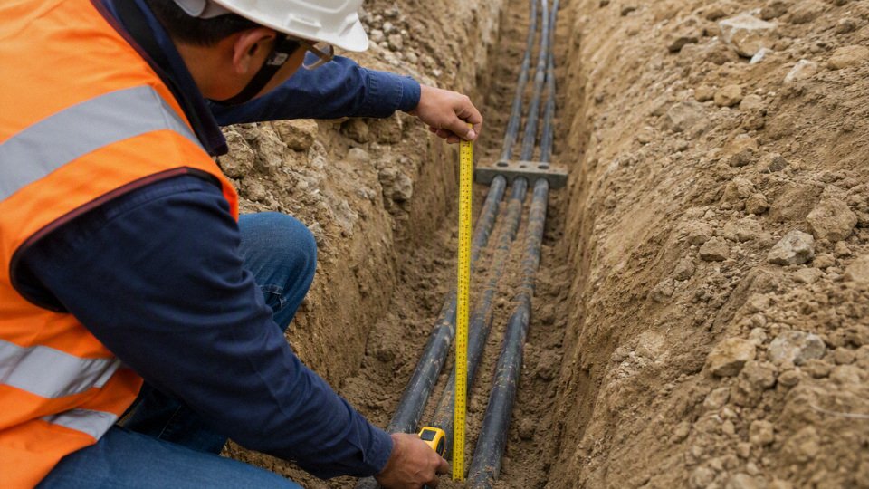
The trade-off is practical: deeper burial improves protection against casual excavation and surface activity, but it can increase trench cost, repair time, and thermal resistance around the cable. That trade-off flips when the route has heavy traffic, unstable reinstatement, aggressive digging risk, or a client standard that sets a minimum depth. In those cases, mechanical security and compliance usually matter more than easy access.
Check that the protection system is complete, not just deep enough:
- trench depth measured from finished ground level, not temporary formation level;
- screened bedding under and around the cable or duct;
- duct selection where cables pass under roads, slabs, crossings, or areas likely to be excavated;
- selected backfill without rubble, scrap rebar, bricks, or sharp stone;
- warning tape roughly 150 mm to 300 mm above the cable, subject to local practice;
- route markers, marker posts, or surface identification where the site needs them;
- permanent route drawings with offsets from fixed features;
- separation from water, gas, telecoms, process pipework, and other power circuits;
- extra protection at risers, wall entries, pits, chambers, and service crossings.
The electrical check must be done at the chosen installation depth and environment. Current rating depends on conductor size, insulation temperature limit, soil thermal resistivity, burial depth, ambient ground temperature, grouping with other circuits, and whether the cable is direct buried or installed in duct. If the design assumes cool, moist soil but the actual route runs through dry made ground beside a hot process area, the installed rating can be meaningfully lower than the spreadsheet suggests.
Translate the approved installation decision into the purchasing specification. At minimum, the RFQ or purchase order should state:
| Procurement item | What to confirm before release |
|---|---|
| Conductor | Copper or aluminium, cross-section, class, and project preference |
| Core count | Single-core or multi-core, neutral requirement, spare cores if specified |
| Voltage rating | System voltage and required cable voltage designation |
| Insulation and sheath | Material, temperature rating, UV or chemical exposure where relevant |
| Armour | Steel wire armour type and whether it is used for earthing continuity |
| Compliance | Project standard, destination documentation, CPR or fire performance where applicable |
| Evidence pack | Routine test reports, certificates, datasheets, drum list, and traceability requirements |
| Logistics | Drum length, drum size, packing method, marking, shipping sequence, and delivery schedule |
Do not let procurement reduce the cable to “SWA, correct size, cheapest compliant offer” until the buried environment has been reviewed. The wrong sheath, incomplete documents, unsuitable drum lengths, or missing test certificates can delay installation just as effectively as a trench problem.
For export or bulk projects, involve supplier engineering support early. Share the destination country, route drawings, trench detail, soil assumptions, expected operating load, grouping arrangement, earthing design, documentation requirements, and any client specification. Shandong Jinda Special Cable Group can review those inputs against its cable manufacturing and technical support scope, then propose a cable construction and documentation package aligned with the actual buried installation.
Before approving the trench or ordering SWA cable, request a technical review of the burial environment, cable rating, and project documentation package. Send the route classification, soil and traffic conditions, required service life, voltage and load data, earthing arrangement, applicable standard, preferred drum lengths, delivery schedule, and any site photos or drawings so the installed cable is safe, compliant, and maintainable.