A power cable that is fine on a drawing can have a rough life once it leaves the panel room: dragged across tray edges, buried in wet ground, clipped to steelwork, or squeezed near pumps and conveyors. One damaged feeder can mean nuisance trips, failed insulation tests, emergency cable pulls, and lost production hours that cost far more than the cable itself. That is why steel wire armoured cable is specified where electrical performance has to survive mechanical abuse, site movement, and long service intervals.
Steel wire armoured cables are used for fixed power distribution in industrial plants, buildings, utilities, and outdoor or underground installations where the cable needs mechanical protection as well as electrical insulation. Typical uses include low-voltage feeders, submains, pump supplies, lighting circuits, and armoured medium-voltage project cables where specified by design standards.
The useful question is not simply “can SWA carry power?”—almost any correctly sized power cable can do that. The better question is where the armour earns its weight, cost, bending penalty, and termination effort, and where another cable construction would be easier to install and maintain.

Typical SWA cable applications
Steel wire armoured cable is mainly used where power circuits need mechanical protection as well as normal electrical insulation: buried routes, outdoor feeders, plant-floor distribution, utility sites, and long fixed runs between equipment. The armour is not a magic shield; it reduces damage from impact, crushing, rodents, and rough handling, but the final suitability still depends on sheath material, gland selection, earthing practice, corrosion exposure, bending radius, and the project standard.
Underground power distribution
SWA is a common choice for underground low-voltage distribution and many medium-voltage feeder routes because it tolerates the abuse that buried cables see before they ever carry load. Direct burial, duct banks, yard crossings, service entrances, and sub-main feeders between buildings all put the cable near excavators, compacted backfill, settlement, water pockets, and the occasional maintenance crew with a shovel and poor drawings.
Typical underground uses include:
- Direct-buried site feeders from a main switchboard to workshops, pump houses, guard houses, lighting panels, or remote distribution boards.
- Duct bank circuits where the cable may still be pulled, scraped, or exposed during future civil work.
- Service entrance runs from utility metering points, transformers, or ring main units into buildings.
- Yard distribution across factories, logistics sites, ports, mines, and treatment plants.
- Routes with excavation risk, especially where cable markers and as-built drawings are not always respected.
The mechanism is straightforward: the steel wire layer spreads local impact and gives the cable a tougher outer structure before the sheath and insulation are damaged. The trade-off is weight and installation effort. A large multicore SWA feeder can be stubborn in a trench, needs proper rollers on a long pull, and will punish a crew that tries to bend it tighter than the manufacturer’s stated limit, commonly somewhere around 8 to 15 times the overall diameter depending on construction.
Industrial plants
In factories, mines, cement plants, steel plants, chemical facilities, and heavy workshops, SWA is often used for fixed power distribution to motors, pumps, conveyors, crushers, compressors, process skids, substations, control rooms, and distribution boards. These are not gentle environments. Cables pass near forklift routes, steelwork, vibrating machinery, hot surfaces, washdown zones, spilled material, and maintenance platforms where someone eventually drops a spanner.
Common industrial applications include:
- Motor and pump feeders for fixed equipment, especially where the route includes tray, wall, trench, or outdoor sections.
- Conveyor and crusher circuits in aggregate, mining, and cement plants, where impact and dust are normal operating conditions.
- Compressor and process-line supplies where cable routes may run along pipe racks or plant steel.
- Workshop distribution for welding bays, machine tools, hoists, and local panels.
- Substation and control-room feeders from transformers, switchgear, and MCCs to plant loads.
In practice, I would not select SWA only because “the site is industrial.” I would look at the actual route: tray height, forklift exposure, chemical splash, heat, pulling length, glands, and how often maintenance teams modify the area. For a clean indoor panel-to-panel run inside protected trunking, unarmoured cable or busbar may be cheaper and easier. For a crusher house, pump station, or outdoor pipe rack, the extra cost of armour is often small compared with one cable strike and a production stop.
Commercial buildings, campuses, and public facilities
Commercial SWA use is usually less dramatic but still important. Main incoming supplies, sub-main feeders, outdoor lighting circuits, mechanical plant rooms, HVAC equipment, data center auxiliary power, and inter-building distribution often need a fixed cable that can survive installation through risers, trenches, service yards, and roof plant areas.
Typical locations include:
- Shopping centers, hospitals, schools, and campuses with feeders between transformer rooms, switch rooms, and separate buildings.
- Mechanical plant rooms supplying chillers, pumps, air handling units, smoke extract fans, and packaged plant.
- Outdoor lighting and perimeter circuits where cables run to columns, bollards, gates, CCTV poles, and security equipment.
- Data center auxiliary power for pumps, condensers, fuel systems, and external support equipment, subject to the facility’s redundancy and fire strategy.
Fire performance often becomes the deciding detail in these environments. In public buildings, transport facilities, tunnels, and confined escape routes, project specifications may call for low-smoke zero-halogen, flame-retardant, or fire-resistant cable variants alongside mechanical armour. Do not assume a standard PVC sheathed SWA satisfies those requirements; the cable type, test performance, installation method, and local code need to align.
Utilities, infrastructure, and municipal networks
SWA is widely used around transformer connections, distribution substations, water treatment plants, wastewater facilities, pumping stations, tunnels, bridges, rail support systems, airports, ports, and municipal networks. These sites combine long routes, outdoor exposure, public access risk, and maintenance work by multiple contractors.
A few practical examples:
- Transformer-to-switchgear connections where the cable may pass through trenches, ducts, or outdoor terminations.
- Water and wastewater plants with pump feeders, blower circuits, screening equipment, sludge handling, and remote panels.
- Tunnels and bridges where access is limited and cable replacement is expensive.
- Airports, ports, and rail support systems with lighting, signals support, pumps, ventilation, shore services, and maintenance buildings.
- Municipal street and utility networks where buried and exposed sections can alternate along one route.
Here the commercial case is often maintainability. A cable that costs less on the purchase order but requires extra mechanical protection, more joints, or earlier replacement may not be cheaper over the asset life. The flip side is that SWA is slower to terminate and heavier to route, so congested retrofit work may need a careful comparison against protected conduits, tray covers, or alternative cable constructions.
Renewable energy, agriculture, and remote installations
Solar farms, wind balance-of-plant systems, battery energy storage sites, irrigation systems, barns, cold stores, grain handling facilities, and rural workshops all use SWA where distribution leaves the neat switchroom and runs across exposed land or working yards.
Decision-relevant uses include:
- Solar farm AC collection circuits from inverters to combiner panels, transformers, or local distribution equipment.
- Battery energy storage auxiliary power for HVAC, fire systems, lighting, controls, and site services.
- Wind farm balance-of-plant cabling for buildings, pumps, lighting, and auxiliary loads.
- Irrigation pumps and field distribution where cable routes may be buried, damp, remote, or exposed to animals.
- Agricultural buildings and cold stores where rodents, washdown, corrosion, and mechanical knocks are routine.
For renewables and rural sites, UV resistance, water exposure, rodent risk, soil condition, and earthing design matter as much as the armour. Seasonal ground movement and poor drainage can be rough on cable entries; I have seen good cable installations compromised by cheap glands, missing shrouds, and junction boxes mounted where water runs straight down the wall into the entry.
Outdoor, exposed, hazardous, and harsh routes
SWA is often installed on cable trays, ladder racks, walls, perimeter fences, temporary-to-permanent project feeds, and exposed outdoor structures. It suits fixed routes exposed to weather, sunlight, accidental impact, and animal damage, provided the sheath is rated for the exposure and the support system avoids abrasion and over-tight cleats.
Hazardous areas need a stricter view. In petrochemical plants, fuel storage areas, and dusty industrial zones, SWA may be part of the cabling system, but the cable alone does not make the installation suitable for the classified area. Glands, seals, bonding, ingress protection, certification, enclosure entries, inspection regime, and the applicable hazardous-area standard must all match the zone and gas or dust group.
Where SWA is not automatically the right answer
SWA should not be treated as a universal cable for every demanding job. Review alternatives or special constructions in these cases:
- Marine and offshore service, where salt corrosion, fire performance, oil resistance, mud resistance, and marine approvals may govern the design.
- Subsea or continuously submerged routes, which need cables specifically designed for water pressure, longitudinal water blocking, and termination sealing.
- Flexible machinery and moving equipment, because standard SWA is for fixed installation, not continuous flexing.
- High-frequency, VFD, or sensitive instrumentation routes, where screening, EMC performance, conductor symmetry, and earthing become critical.
- Single-core AC circuits, where steel armour can create magnetic heating issues; non-magnetic armour or a different installation arrangement may be required.
- Highly corrosive chemical or coastal exposure, where sheath, armour protection, glands, and tray material need to be selected as a system.
The safe selection boundary is simple: SWA is strongest as a fixed power cable where mechanical abuse is credible and the installation can accommodate its weight, bending radius, terminations, and earthing. Once the route involves continuous movement, special fire performance, classified areas, seawater, high-frequency drives, or single-core AC magnetic effects, the armour choice has to be engineered rather than assumed.
Why armour changes performance
Armour changes cable performance because it adds a load-spreading metallic layer between the electrical core and the jobsite. That improves survivability against impact, crushing, abrasion, and animal attack, but it also changes termination practice, earthing design, bending behavior, pulling load, heat dissipation, and, in some AC cases, magnetic losses.
Mechanical protection is not just “extra thickness”
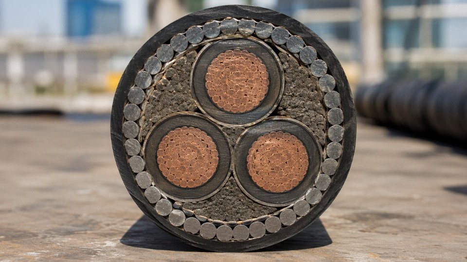
Steel wire armour works because many galvanized steel wires sit around the bedding layer and share mechanical abuse that would otherwise be taken by the sheath, insulation, or conductor screen. A shovel strike, a sharp stone in backfill, or a cable tray clamp tightened by an over-enthusiastic fitter does not become harmless, but the force is spread around the cable circumference instead of being concentrated at one thin point.
In practice, that load distribution matters in four common damage modes:
- Impact: The armour absorbs and redistributes a blow before it reaches the insulation system. This is one reason SWA is preferred where cables run near maintenance traffic, stores areas, pumps, conveyors, or outdoor plant.
- Crush: The steel wire layer increases resistance to local compression from backfill, concrete edges, sleepers, or cable cleats. It does not make the cable suitable for unlimited burial pressure; trench design and bedding still matter.
- Abrasion during installation: Pulling through ducts, dragging across rough ground, or laying into a trench can scrape an outer sheath. With SWA, the armour gives a second layer of mechanical tolerance if the sheath is bruised, although sheath damage should still be repaired or the section replaced.
- Long-service nuisance damage: Vibration, thermal movement, rubbing on tray edges, and occasional knocks from tools are less likely to progress into insulation damage when the cable has a properly manufactured armour layer.
The mechanism is simple enough, but the procurement implication is often missed: the armour protects the cable best when the rest of the installation is not lazy. Sand bedding, proper duct entries, cable rollers, sensible tray support spacing, and radius control still pay for themselves. I have seen armoured cable survive ugly handling, but I have also seen it ruined by a kink at a manhole entry because the crew treated “armoured” as “unbreakable.”
Installation survivability improves, but pulling discipline still matters
SWA cable is much more forgiving during installation than an equivalent unarmoured power cable. It tolerates rougher routes through ducts, trench transitions, exposed tray runs, plant rooms, and areas where vehicles or maintenance staff may contact the cable after energization.
That does not remove the usual installation limits. A heavier armoured cable can create higher pulling tension, larger sidewall pressure at bends, and more difficulty at glands and panels. Typical minimum bending radius is often in the range of 8 to 15 times the overall cable diameter, depending on construction, conductor type, armour, sheath material, and the manufacturer’s data sheet. For a large multicore cable, that radius can quickly become a real layout constraint inside a kiosk or motor control center.
Useful checks before installation include:
- Pulling route geometry: Count bends, duct offsets, manhole entries, and tight tray drops. A route that looks acceptable on a drawing may be miserable with a stiff armoured cable.
- Pulling method: Confirm whether the cable will be pulled by conductor, stocking grip, pulling eye, or drum payout with rollers. The allowable method is manufacturer-specific.
- Drum handling: SWA drums are heavy. Forklift fork length, drum jacks, brake control, and floor condition affect cable damage more than most buyers expect.
- Termination space: Armour glands, banjos, earth tags, shrouds, heat-shrink boots, and bending clearance need room. A cramped gland plate is a common source of poor workmanship.
- Backfill quality: Armour helps against stones, but it is not a license to dump sharp rubble onto the cable. The outer sheath is still the environmental barrier.
A thicker or heavier armoured cable is not automatically the better engineering choice if it forces excessive pulling tension, bending stress, poor termination fit, heat buildup, or unnecessary installation cost. The preferred design flips when the mechanical risk is modest but the route is tight, the run is heavily grouped, or the panel space cannot accept the larger gland arrangement.
Rodent and animal resistance has limits
Steel wire armour can significantly reduce damage from rodents, burrowing animals, and site wildlife because teeth or claws meet a hard metallic layer instead of only polymer sheath. That is especially valuable in substations, farm installations, water treatment works, rail-side cabinets, warehouses, and outdoor utility routes where rats, mice, or burrowing animals are not theoretical.
It is still not absolute protection. In severe infestation zones, cable route management is part of the engineering package:
- seal building entries and duct mouths;
- avoid food waste and nesting material near cable routes;
- use proper trench depth and bedding;
- keep cable runs off floors where practical;
- inspect sheath damage before water ingress starts;
- consider additional ducting, covers, or barriers in known attack areas.
Armour reduces probability; it does not eliminate exposure. If rodents are already chewing plastic conduit, air hoses, and control wiring, an SWA route should be treated as one layer of defense, not the full pest control plan.
Earthing and fault current behavior must be designed, not assumed
The steel wire armour may be connected to earth through proper cable glands, earth tags, banjos, bonding conductors, and gland plates. Whether that armour can serve as the circuit protective conductor is a separate engineering question, not a visual inspection decision.
The armour path has resistance and impedance. During a fault, current must be high enough to operate the protective device within the required disconnection time, and the armour must withstand the thermal and electromechanical stress until that happens. If the armour path is undersized, poorly bonded, corroded, or interrupted by bad gland practice, two bad outcomes are possible: the armour overheats during the fault, or the protection does not trip reliably.
The decision depends on:
- prospective fault current at the installation point;
- protective device type and trip curve;
- required disconnection time under the applicable wiring rules;
- armour material, cross-sectional area, and resistance;
- cable length and conductor size;
- gland type, bonding hardware, and enclosure continuity;
- parallel earth paths, if any;
- inspection and test results after installation.
The steel wire armour in an SWA cable automatically makes the cable fire-resistant and suitable as the protective earth.False
Armour provides mechanical protection. Fire performance depends on the cable compounds and tested design, while use of armour as a protective conductor depends on verified fault-current, impedance, bonding, and regulatory requirements.
In a procurement specification, the safe wording is not “SWA shall be earthed, therefore CPC is covered.” A better requirement is to state whether a separate protective conductor is required, whether the armour is to be bonded at one or both ends, what standard or project rule applies, and what test records must be provided at commissioning.
Thermal performance changes with construction and installation
Armour improves physical strength, but it can also increase outside diameter and change the cable’s thermal behavior. Current-carrying capacity is set by how well heat leaves the conductor, insulation, bedding, armour, sheath, and surrounding environment. The armour layer may provide some metallic heat spreading, but the larger construction, bedding materials, sheath, grouping, and installation method can reduce the final ampacity compared with a simpler cable in free air.
The thermal path changes again by installation condition:
| Installation condition | What armour changes | Practical buying or design issue |
|---|---|---|
| Buried direct in soil | Larger diameter and sheath exposure interact with soil thermal resistivity | Soil condition, burial depth, spacing, and seasonal drying can dominate the rating |
| In duct | Duct air space and poor heat transfer may limit current more than cable construction | Avoid using free-air ratings for ducted runs |
| On tray in groups | Larger cable diameter can worsen grouping and spacing constraints | More tray width or derating may be needed |
| In plant rooms | Ambient temperature, ventilation, and cable bunching affect insulation life | Check against 70 degrees Celsius PVC or 90 degrees Celsius XLPE conductor temperature limits as applicable |
| Near heat sources | Armour does not protect insulation from sustained thermal aging | Route away from steam lines, furnaces, hot roofs, and solar-loaded surfaces |
For XLPE insulated designs, short-circuit conductor temperature limits are often specified up to 250 degrees Celsius for a defined fault duration, but that does not mean the cable can run hot continuously. Continuous rating, emergency loading, and short-circuit withstand are different checks. Mixing them up is how plants end up with brittle sheaths, cooked terminations, and nuisance trips after the first hot season.
The boundary here is important: there is no honest universal percentage derating for “SWA versus non-armoured.” The estimate needs conductor size, insulation, sheath material, installation method, soil or ambient conditions, grouping, spacing, and the rating standard used for the project.
Single-core AC cables need special attention to magnetic effects
Steel wire armour is usually a poor choice around single-core AC power cables unless the design has been specifically engineered for it. A single AC conductor produces a changing magnetic field; ferromagnetic steel armour around that one phase can develop induced currents, magnetic hysteresis losses, heating, and voltage effects that are not present in the same way in balanced multicore construction.
That is why aluminum wire armour or other non-magnetic armour is commonly specified for single-core AC applications. In three-phase multicore cable, the phase currents are physically close and tend to cancel much of the external magnetic field. With single-core runs, the field geometry is different, especially if phases are separated or installed in a poor formation.
The practical checks are straightforward:
- confirm whether the cable is multicore or single-core;
- confirm AC or DC service;
- check armour material in the data sheet, not just the word “armoured”;
- keep single-core phase spacing and formation consistent with the design;
- avoid closed ferromagnetic loops around individual phases;
- verify gland plates, cleats, and surrounding steelwork requirements.
This is one of those details that can look academic until a site finds hot armour, warm gland plates, or unexplained losses on a high-current feeder.
Corrosion protection depends on the sheath system
Galvanized steel wires are not intended to sit directly in wet soil, chemicals, or standing water for years. The bedding and outer sheath protect the armour from the environment. Once the sheath is cut, split, poorly sealed, or chemically attacked, water can reach the armour and corrosion becomes a long-term reliability issue.
Common corrosion triggers include:
- damaged sheath from pulling over sharp edges;
- poorly sealed outdoor glands;
- water-filled ducts with no drainage;
- aggressive soil chemistry;
- hydrocarbons, solvents, or process chemicals incompatible with the sheath;
- UV exposure on sheath materials not suitable for long outdoor service;
- capillary water movement into terminations.
A galvanized layer buys time, not immunity. For wet, coastal, chemical, or buried projects, the sheath compound, gland sealing, route drainage, and inspection access deserve as much attention as the armour itself.
Armour is not the same as fire performance
Armour gives mechanical protection. It does not automatically provide flame retardance, low smoke performance, halogen-free behavior, or circuit integrity during fire. Those properties come from the insulation, bedding, sheath compounds, mica or fire barrier tapes where used, and the tested cable design.
The distinction matters in tunnels, public buildings, data centers, hospitals, underground stations, emergency systems, and enclosed escape routes. A mechanically tough PVC sheathed SWA cable may be entirely wrong where low smoke zero halogen performance is required. Likewise, a fire-resistant circuit cable must be selected and installed as a tested system, including supports and accessories where the applicable standard requires it.
For a serious specification, call out the required behavior clearly:
- flame retardant;
- low smoke;
- low halogen or zero halogen;
- fire-resistant circuit integrity;
- oil, UV, water, or chemical resistance;
- installation standard and test standard required by the project.
Armour changes how well a cable survives the plant floor. The rest of the cable design determines how it behaves electrically, thermally, chemically, and in fire, so the correct SWA selection has to be made from the route conditions and protection study, not from armour thickness alone.
Construction and material choices
SWA cable suitability is decided less by the word “armoured” and more by the full construction stack: conductor metal, insulation, bedding, armour, sheath compound, markings, and test regime. Two cables with the same voltage rating and conductor size can behave very differently in a wet duct bank, a refinery tray, or a long export drum simply because those material choices were not specified tightly enough.
Conductors
The conductor decision usually starts with copper versus aluminum. Copper gives higher conductivity in a smaller cross-section, better termination familiarity, and generally stronger short-circuit performance for the same physical size. Aluminum reduces cable weight and material cost, which matters on long feeders, elevated trays, and export projects where freight is not a rounding error.
The trade-off shows up at the termination and maintenance end. Aluminum needs correctly rated lugs, oxide control, proper jointing practice, and torque discipline; a lazy termination on aluminum can become a hot joint months after commissioning. Copper is more forgiving, but the installed cost can be painful on large low-voltage feeders.
Common conductor choices include:
- Stranded circular conductors for flexibility and easier handling in smaller and medium sizes.
- Shaped or sector conductors in multi-core power cables to reduce overall diameter and improve compactness.
- Class 2 compacted stranded conductors for many fixed power installations, subject to the governing standard and purchaser specification.
- Flexible conductor classes only where the cable design, glands, and application actually support movement; SWA is not normally bought as a high-flex trailing cable.
Cross-sectional area must be selected from load current, voltage drop, fault level, installation method, soil or ambient temperature, grouping, and allowable conductor temperature. Typical conductor operating limits are often 70°C for PVC-insulated designs and 90°C for XLPE-insulated designs, but the usable ampacity still depends on how the cable is installed and derated.
Insulation, bedding, armour, and sheath
The insulation system sets the electrical and thermal envelope. PVC remains common for standard low-voltage distribution, especially where cost and general-purpose installation are the main drivers. XLPE is often preferred where higher operating temperature, improved dielectric performance, and better short-circuit withstand are needed; XLPE short-circuit limits are commonly specified up to 250°C for defined fault durations, but the exact value belongs in the applicable cable standard and manufacturer data sheet.
Project-specific insulation may be justified for high ambient temperature, aggressive environments, or special fire-performance requirements. The boundary is simple: do not pay for exotic insulation unless the site condition, code requirement, or lifecycle risk actually demands it.
| Layer or feature | Practical function | Selection issues that affect service life |
|---|---|---|
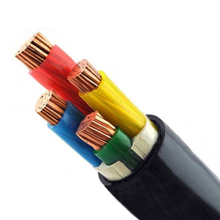
| Bedding layer | Cushions the insulated cores and creates a reasonably circular base for the armour | Poor bedding consistency can let armour wires bite into the cable structure during bending, pulling, or thermal cycling |
| Galvanized steel wire armour | Provides mechanical protection and, where designed and permitted, may contribute to earth continuity | Wire size, lay, coverage, corrosion protection, and gland compatibility matter; armour is not a substitute for correct circuit protection design |
| Steel tape armour | Used in some regional cable designs and installation traditions | Offers a different protection profile from wire armour and must match local standards, bending expectations, and installation method |
| Aluminum or non-magnetic armour | Used for single-core AC circuits to avoid excessive circulating losses and heating from magnetic steel armour | Needs careful earthing, bonding, and installation review; this is not a place for “same as multi-core” purchasing habits |
| Outer sheath | Protects against moisture, sunlight, abrasion, chemicals, flame spread, and biological attack depending on compound | PVC, PE, LSZH, oil-resistant, UV-resistant, termite-resistant, anti-rodent, flame-retardant, and chemical-resistant compounds serve different risks |
Outer sheath selection is where buyers often under-specify. A black PVC sheath may be perfectly acceptable in many fixed industrial applications, but exposed solar farms, coastal yards, oily workshops, buried routes, and tunnel installations can require a different compound or verified additives. PE may improve moisture resistance and toughness in some buried applications, while LSZH is commonly considered for indoor public or enclosed spaces where smoke density and acid gas emissions are restricted by project rules.
Optional performance features should be specified by function, not by buzzword. Water-blocked or longitudinally water-resistant construction can limit moisture migration after sheath damage. Fire-resistant cable construction is different from flame-retardant sheathing; one is about circuit integrity under fire conditions, the other is about limiting flame spread. Enhanced UV resistance, low smoke density, low acid gas emission, and special sheath colors for project identification all need a stated standard, test method, or buyer requirement.
Identification, handling, and installation compatibility
Core identification seems mundane until commissioning crews are working in a wet trench at dusk. Phase colors, neutral and protective conductor identification, printed legends, voltage designation, manufacturer name, standard reference, batch traceability, and meter marking all reduce installation errors and make later maintenance less painful.
Dimensional data should be checked before purchase, not after drums arrive. The cable’s overall diameter drives gland size, cleat spacing, tray fill, duct occupancy, bending room, and pulling arrangement. Typical minimum bending radius is often around 8 to 15 times the overall cable diameter, depending on construction, conductor type, armour, and sheath material, but the final value must come from the manufacturer’s data.
For procurement and site planning, ask for:
- Overall diameter and tolerance.
- Approximate weight per meter.
- Minimum bending radius during installation and after installation, if differentiated.
- Maximum pulling tension and whether pulling eyes are required.
- Drum length, drum dimensions, and gross drum weight.
- Storage requirements, including UV exposure, end sealing, standing water, and minimum handling temperature.
- Compatibility with specified glands, cleats, trays, ducts, and earthing or bonding hardware.
A cable that is electrically correct but too stiff, too heavy, or mismatched to the gland package is still a procurement failure. I have seen crews lose more time fighting bend radius and gland entry alignment than they ever saved by buying the cheapest compliant-looking cable.
Manufacturing quality controls and supply consistency
Quality control on SWA cable is not one final high-voltage test at the end of the line. It is a sequence of checks that catch different failure modes: conductor resistance testing confirms metal size and conductivity; insulation thickness checks protect electrical margin; spark testing and voltage testing screen for insulation defects; armour inspection verifies wire application, lay, and coverage; sheath integrity and dimensional verification confirm the finished cable can be installed and sealed as specified.
For international projects, the commercial risk is consistency across drums, batches, and delivery phases. That is where an integrated manufacturer matters. Jinda’s R&D, production, sales, technical support, and after-sales structure, backed by five production bases, 470,000 m² of manufacturing space, and supply experience across more than 50 countries, is relevant when buyers need repeated SWA cable builds rather than one isolated shipment. Large-volume procurement is not only about price per meter; it is about stable construction, traceable batches, coordinated documentation, and technical support when project standards, sheath requirements, or packing constraints change before delivery.
Selection criteria for projects
Start with the load schedule, not the cable catalogue. A technically correct SWA cable is selected by matching electrical duty, route conditions, protection settings, termination hardware, documentation requirements, and replacement risk; if one of those is guessed, the cheap cable usually becomes expensive during installation or commissioning.

Electrical load and protection coordination
The first calculation is not only full-load current. For a useful specification, give the cable supplier or design engineer:
- Continuous current demand and expected diversity factor
- Duty cycle, especially for cyclic machines, pumps, crushers, cranes, compressors, and HVAC plant
- Motor starting current and starting duration
- Permitted voltage drop at running load and during start
- Harmonic content from VFDs, UPS systems, rectifiers, LED drivers, or data-centre loads
- Power factor, including correction equipment if fitted
- Spare capacity or future expansion allowance
- Protective device type, rating, trip curve, breaking capacity, and earth-fault arrangement
The mechanism is simple but often missed: current heats the conductor, harmonics add heating in conductors and metallic parts, voltage drop affects equipment torque or control stability, and the protective device must disconnect faults before the conductor insulation or armour bonding path is overstressed. Do not size SWA cable from ampacity alone; voltage drop and short-circuit withstand can become the controlling criteria on long runs or high-fault-level feeders.
There is a commercial trade-off here. Oversizing copper or aluminium increases purchase cost and pulling effort, but may reduce lifetime energy loss and avoid a second cable run later. The preferred choice flips when the route is short, accessible, and lightly loaded; then future allowance may matter less than installation speed and standard stock availability.
SWA cable selection should consider voltage drop, short-circuit withstand, installation conditions, and protective-device coordination, not only current rating.True
This follows standard electrical design practice. The controlling constraint changes with route length, ambient conditions, grouping, fault level, and load profile.
Voltage rating, system type, and core configuration
For low-voltage power distribution, SWA cables are commonly specified at 0.6/1 kV. Medium-voltage armoured designs are commonly specified up to 33 kV, but the exact construction, testing, screen arrangement, and accessories must follow the project standard and local utility requirements.
Define the system clearly before asking for a quotation:
| Decision point | What to confirm | Why it affects the cable |
|---|---|---|
| AC or DC | Polarity, insulation stress, earthing philosophy | DC systems may need different design checks and termination practice |
| Single-phase or three-phase | Number of live conductors and neutral requirement | Prevents underspecified cores or unnecessary spare cores |
| Neutral sizing | Full, reduced, or oversized neutral | Non-linear loads can make neutral current higher than expected |
| Protective earth | Armour used as CPC, separate earth conductor, or both | Depends on fault current, bonding, regulations, and gland continuity |
| Balanced or unbalanced load | Phase loading and neutral current | Drives core count and conductor sizing |
Two-core SWA is common for single-phase circuits where a separate protective conductor strategy is defined. Three-core is used for many three-phase loads without neutral. Four-core covers three-phase plus neutral, while five-core can include a dedicated protective conductor where project rules or fault-loop calculations require it. Multi-core armoured control cables need a different conversation: voltage, signal type, screening, EMC exposure, and core identification matter as much as mechanical protection.
Conductor sizing and installation conditions
Ampacity depends heavily on where the cable actually sits after the civil contractor is finished. A cable in open air on ladder behaves differently from one buried in warm, dry soil beside three other loaded circuits.
Check these installation variables before freezing the size:
- Direct burial, duct, tray, ladder, indoor riser, or clipped surface installation
- Ambient air temperature or ground temperature
- Soil thermal resistivity, especially in dry sand, backfilled trenches, or seasonal drought areas
- Grouping with other loaded cables
- Burial depth and duct fill
- Sheath exposure to water, sunlight, oil, fuel, solvents, cementitious materials, or process chemicals
- Mechanical impact zones, vehicle crossings, workshop edges, rodent presence, and flood risk
Soil thermal resistivity is a quiet budget killer. If the design assumes moist native soil but the installer uses dry backfill or routes through a hot service corridor, conductor temperature rises and the allowable current falls. PVC insulated designs are typically based around 70 degrees Celsius conductor operation, while XLPE designs are typically rated around 90 degrees Celsius, subject to the manufacturer data and installation standard. XLPE also commonly has higher short-circuit temperature limits, often up to 250 degrees Celsius for a specified fault duration, but that must be checked against the actual cable datasheet and protection clearing time.
Economic conductor sizing deserves attention on feeders that run many hours per year. A larger conductor costs more on day one, yet lower I²R losses may repay that cost where energy prices are high or the plant runs continuously. That conclusion stops holding for standby circuits, short intermittent loads, or projects where the route may be dismantled before the payback period.
Fire, smoke, and environmental performance
Fire performance is not one product label. Specify the required behavior by location and regulation:
- Flame-retardant sheath for reduced flame spread in general building or industrial routes
- LSZH materials where low smoke and reduced acid gas are required, such as public buildings, tunnels, transport hubs, underground areas, and confined escape routes
- Fire-resistant cable where circuit integrity during fire is required for emergency systems, alarms, smoke extraction, or life-safety equipment
- UV-resistant outer sheath for outdoor exposure
- Chemical- or oil-resistant sheath where the cable passes through workshops, petrochemical areas, wastewater facilities, or battery rooms
The trade-off is handling and environment. Some LSZH compounds are less forgiving than standard PVC during cold pulls or rough installation, so bending radius, pulling tension, and site temperature need checking against the manufacturer’s data. Typical minimum bending radius for SWA is often in the range of 8 to 15 times the overall cable diameter, depending on construction, conductor type, armour, and sheath, but the project should use the current cable datasheet rather than a rule of thumb.
Standards, approvals, terminations, and supply
Standards alignment is where procurement mistakes show up late. Confirm whether the project requires IEC, British, European, national utility, client-specific, or market-specific approval, and make sure the quotation covers product design, routine testing, type-test evidence where required, cable marking, drum labels, and documentation language in English.
Termination hardware must be selected with the same discipline as the cable:
- Correct gland type for indoor, outdoor, hazardous, wet, or corrosive locations
- Brass, nickel-plated brass, stainless steel, or other gland material to suit the enclosure and atmosphere
- Armour clamp range matched to the actual armour diameter
- Shrouds, sealing washers, earth tags, locknuts, and bonding jumpers where required
- Enclosure IP rating maintained after glanding
- Compatibility with sheath material and cable overall diameter
I have seen good cable blamed for bad glands more than once. A loose armour clamp, missing serrated washer, or painted gland plate can turn a neat installation into an earth-continuity problem.
For international procurement, include production lead time, drum size limits, cut-length tolerance, export packing, container loading plan, sequential metre marking, English cable marking, inspection hold points, routine test reports, and after-sales technical support expectations. Lifecycle cost should then be judged against installation labour, route protection, outage cost, maintenance access, replacement difficulty, and failure consequence. In a buried feeder under a paved yard, reliability and documentation are worth more than a small saving on the purchase order.
Installation and termination essentials
SWA cable only delivers its mechanical and electrical value if the installation preserves the armour, sheath, insulation geometry, and earth path from drum to termination. Most SWA failures I have seen after commissioning were not caused by bad cable design; they came from crushed bends, wet cable ends, poor glands, undocumented burial routes, or a pull that was “made to fit” with too much force.
Route planning before the drum is opened
Walk the route before issuing the pull permit. Drawings are useful, but site conditions change: a tray fills up, a pump base shifts, a civil contractor adds a drain, or a duct that looked free on paper has three old cables and a mud plug inside.
Check at least the following:
- Trench depth against local code, project specification, road crossing requirements, and future excavation risk.
- Duct capacity, internal condition, bend count, draw-pit spacing, and whether the selected cable outside diameter is still realistic.
- Tray and ladder loading, including existing cables, future allowance, support span, and corrosion condition.
- Bend locations at elbows, pit entries, risers, transformer plinths, MCC bases, and gland plates.
- Separation from steam lines, hot process pipework, furnace areas, roof solar gain, and other heat sources that reduce ampacity.
- Segregation from instrumentation, control, communication, and data circuits where EMC or project rules require it.
- Crossing points with other services, preferably at right angles and with physical protection where needed.
- Access for inspection, gland maintenance, testing, and eventual replacement.
Heat and grouping are easy to underestimate. Armour improves impact resistance, but it does not magically remove heat; in some installations it adds thermal resistance and makes derating more important.
Handling, pulling, and bending control
Keep drums upright, store them on firm ground, and reject or quarantine drums with broken flanges, crushed lagging, exposed cable, or missing end caps. Cable ends should stay sealed until termination because moisture tracking into the conductor or bedding can turn into low insulation resistance later, especially after a few heating cycles.
For pulling work:
- Roll the drum in the marked direction and never let loops fall off the flange.
- Use cable rollers, corner rollers, bell mouths, and clean duct entries.
- Avoid dragging the sheath over rebar, tray edges, concrete, sharp stones, or Unistrut cut ends.
- Use pulling socks, suitable swivels, winches with load indication, and approved lubricants for duct pulls.
- Confirm pulling tension and sidewall pressure limits from the cable supplier or project specification.
- Break long or complex routes into staged pulls rather than relying on a big winch and optimism.
- Keep communication open between drum end, winch end, and intermediate bend points.
Minimum bending radius is not a suggestion. For many SWA constructions it is commonly around 8 to 15 times the overall cable diameter, but the correct value depends on conductor type, armour, sheath, voltage class, and the manufacturer’s datasheet. The worst bends often happen after the pull, when installers force the cable into a gland plate or around an equipment base.
SWA cable can usually be bent as needed as long as the outer sheath does not crack.False
Over-bending can distort insulation, loosen armour wires, or stress conductor strands even when the visible sheath still looks acceptable.
Direct burial, trays, glands, and final checks
For direct burial, prepare the cable bed properly. Use sand or selected fine backfill around the cable, remove sharp stones, maintain specified cover depth, and install warning tape or marker tiles above the cable. Road and vehicle crossings need extra mechanical protection such as ducts, slabs, or project-approved sleeves. Photograph the open trench before backfilling and record offsets from fixed landmarks; buried cable routes become very expensive to “remember” five years later.
For tray and ladder systems:
- Use correctly rated cable cleats or straps, not whatever tie wrap is in the toolbox.
- Set spacing based on cable size, route orientation, short-circuit forces where applicable, and project standard.
- Use corrosion-resistant hardware in wet, coastal, chemical, or washdown areas.
- Install fire barriers or fire-stopping where the route crosses rated walls or floors.
- Leave room for heat dissipation, inspection, and replacement pulls.
Termination quality is where SWA work often separates good contractors from rushed ones. Use the correct armoured cable gland for the cable type, sheath material, armour wire size, ingress protection rating, and hazardous-area classification if applicable. Cut and dress the armour evenly, clamp the wires fully, fit shrouds or seals as specified, and bond the armour where the earthing design requires it. Do not assume armour continuity because the gland “feels tight”; measure it.
Before energization, complete and record:
- Insulation resistance testing with suitable voltage for the cable rating and connected equipment condition.
- Conductor continuity and phase identification.
- Armour bonding and earth continuity checks.
- Sheath inspection, especially at bends, tray exits, and gland entries.
- Voltage withstand or VLF testing where required for medium-voltage circuits and project standards.
- Comparison with factory test records when available.
The installation file should include cable type, voltage class, conductor size, route, drum number, installed length, test results, gland type, termination details, installation date, and buried-route photographs. If those records are missing, the plant may still run, but troubleshooting becomes slower, riskier, and more expensive than it needed to be.
Standards, testing, and documentation
An SWA cable specification is only complete when the product standard, installation rule set, test evidence, and project documents all point to the same intended service. A catalog line saying “SWA cable” is not enough for procurement approval on a plant expansion, tunnel job, utility feeder, or export project, because armour is only one part of compliance.
A cable marked SWA is not automatically suitable for every buried, fire-risk, or public-infrastructure installation.True
Armour describes one construction feature; allowable use depends on the product standard, sheath and insulation compounds, fire performance, earthing method, installation code, and project specification.
Product and installation standards
For many extruded-insulation low-voltage power cables, IEC 60502-1 is a common reference point. It covers rated-voltage classes used widely in industrial and commercial distribution, including many 0.6/1 kV designs. Medium-voltage armoured cable projects usually move into the relevant IEC 60502 medium-voltage parts or national utility specifications; these should not be treated as a simple upsized version of low-voltage cable.
In British and British-influenced project specifications, BS 5467 is often used for XLPE insulated, PVC sheathed armoured power cables, while BS 6724 is commonly specified where low-smoke zero-halogen performance is required. National equivalents may be used in other markets, and large utilities often add their own construction, marking, testing, drum, and inspection requirements.
Installation approval is a separate question. IEC 60364, local wiring rules, utility standards, building codes, fire codes, and project engineering standards determine how the cable may be routed, supported, buried, protected, glanded, earthed, segregated, and derated. This is where many procurement mistakes start: the buyer selects a cable that is electrically adequate, but the installation method later requires a different sheath, fire rating, armour bonding arrangement, or current rating calculation.
Fire performance is not one single test
Fire-related cable language needs careful reading. “Flame retardant,” “low smoke,” “zero halogen,” and “fire resistant” describe different performance requirements, not interchangeable marketing labels.
Common fire-related requirements may include:
- Flame propagation testing, often used to limit how readily cable bunches spread flame along a route.
- Smoke density testing, important in enclosed public areas, tunnels, transit systems, control rooms, and escape routes.
- Acid gas and corrosive gas testing, used where electronic equipment, steelwork, and life safety systems must be protected from aggressive combustion products.
- Halogen content limits, usually tied to LSZH sheath and bedding compounds.
- Circuit-integrity testing, required only when the cable must continue operating during fire for emergency lighting, alarms, smoke extraction, pumps, or life-safety circuits.
The trade-off is practical: LSZH and fire-performance compounds can improve smoke and toxicity behavior, but they may have different abrasion resistance, flexibility, moisture behavior, or cost compared with standard PVC sheaths. In a clean commercial building that trade-off may be obvious; in a wet industrial trench or rough outdoor yard, the sheath compound and installation exposure need a closer check.
Factory tests, type tests, and sample tests
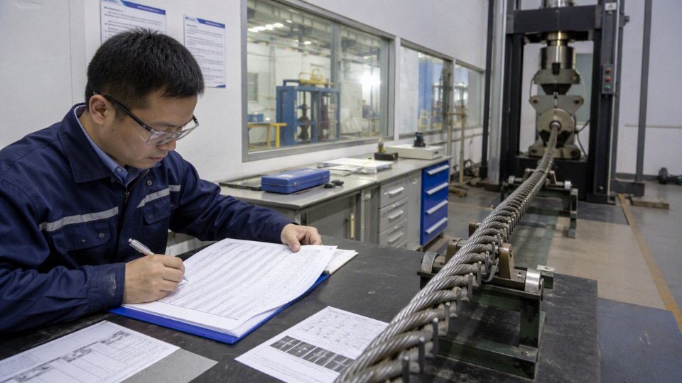
Routine factory tests are the buyer’s first defense against receiving the wrong or poorly made cable. They normally include:
- Conductor resistance checks to confirm conductor size and continuity.
- Insulation resistance measurement.
- High-voltage withstand testing.
- Dimensional checks on insulation, bedding, armour, and sheath.
- Outer sheath integrity checks where specified.
- Marking verification, including voltage grade, core count, size, standard, manufacturer, and meter marking.
- Visual inspection of armour lay, sheath finish, ovality, cuts, dents, and surface defects.
Type and sample tests go deeper. Depending on the standard and purchase specification, they may include mechanical tensile and elongation tests, aging tests, hot set tests for XLPE insulation, impact and crushing tests, flame tests, water resistance checks, and compatibility tests between insulation, bedding, fillers, armour protection, and sheath compounds.
The mechanism behind these tests is simple but important: routine tests catch production errors on actual manufactured lengths, while type tests prove that the design and materials can survive defined thermal, mechanical, electrical, and environmental stresses. A passed type test does not replace routine testing on the shipment, and a passed routine test does not prove the design is suitable for an unverified application.
Procurement documents that prevent disputes
For engineered projects, the purchase file should include more than a purchase order and a datasheet. At minimum, buyers should control:
- Approved cable datasheets.
- Cable schedule showing tag numbers, routes, sizes, voltage class, cores, and lengths.
- Bill of quantities with spare length allowances and drum length requirements.
- Compliance matrix against IEC, BS, national, utility, or project standards.
- Construction drawings or cross-section drawings.
- Installation method statement, especially for burial, tray, duct, tunnel, riser, or hazardous-area routes.
- Inspection and test plan.
- Factory test reports.
- Certificate of conformity.
- Packing list and drum schedule.
- Third-party inspection reports when required by the owner, EPC contractor, utility, or insurer.
Traceability matters after the cable has disappeared into the ground or behind cladding. Batch numbers, drum numbers, production dates, meter marking, laboratory records, and retained samples help resolve later questions about sheath damage, wrong length, installation abuse, thermal overload, or a possible manufacturing issue. Without that trail, every claim becomes an argument between warehouse photos, installer notes, and memory.
A technically strong supplier should be judged on manufacturing control, test capability, export documentation experience, and responsiveness to engineering queries, not only on whether a catalog page lists the required core size. This is especially true for multi-country projects, where the commercial cost of a documentation gap can be worse than a small price difference on the cable itself.
Common mistakes and failure risks
Most SWA cable failures I see are not caused by “bad armoured cable”; they come from treating the armour as a cure-all and skipping the electrical, thermal, and installation checks around it. The armour protects against many mechanical hazards, but it does not automatically solve earthing, heat, chemical exposure, bending damage, or poor termination practice.
Specification errors that create trouble later
- Using steel wire armour on single-core AC circuits without checking magnetic effects.
This is one of the expensive mistakes. On single-core AC cables, ferromagnetic steel armour can be exposed to alternating magnetic flux from the phase conductor. That can drive induced currents, extra losses, and local heating, especially at higher currents or where cables are separated rather than installed in a trefoil or properly grouped arrangement. For single-core AC power, engineers commonly consider non-magnetic armour, such as aluminium wire armour, or a different protection method depending on the standard, fault duty, and installation route. The preferred choice flips when the circuit is DC or when the cable design and installation method have been engineered to avoid the magnetic heating problem. - Assuming the armour is automatically acceptable as the protective conductor.
Steel wire armour may be used as part of the earthing or bonding path in some installations, but only if the design proves it. That means fault-loop impedance checks, continuity verification, correct gland selection, properly fitted earth tags or banjos where required, and compliance with the local wiring rules. A loose gland on an SWA termination can look fine from two metres away and still give you unreliable fault clearing. Selecting only by conductor size.
A cable sized only for nominal load current may still fail the job. Proper selection also needs:- voltage drop over the installed route;
- short-circuit withstand for conductor and armour-related components;
- grouping derating in trays, ducts, trenches, or risers;
- soil thermal resistivity for direct burial;
- ambient temperature inside plant rooms or outdoor enclosures;
- installation method and depth;
- spare capacity for future load growth.
The mechanism is straightforward: higher thermal resistance around the cable slows heat rejection, conductor temperature rises, insulation ages faster, and the “correct” ampacity from a catalogue becomes optimistic.
- Specifying a standard PVC sheath where the environment needs something tougher.
PVC is common and cost-effective, but it is not universal. Project conditions may call for LSZH sheath for enclosed public areas, UV-resistant sheath for exposed outdoor runs, oil-resistant compounds near machinery, chemical-resistant materials for process areas, termite resistance for some buried routes, or enhanced flame performance for tunnels and critical infrastructure. Do not let the cheapest sheath become the weakest part of a very expensive cable route.
Installation mistakes that damage cable before energization
Bending, pulling, or side-loading beyond the cable’s limit.
Typical SWA minimum bending radius is often around 8 to 15 times the overall cable diameter, but the actual value depends on construction, conductor type, armour, sheath material, and the manufacturer’s data. Excessive pulling tension or sidewall pressure at rollers and bends can deform insulation, open small sheath cracks, or disturb armour lay. The nasty part is that the cable may pass a basic continuity check and still have shortened service life.Damaging the outer sheath and leaving the armour exposed.
A nick from a tray edge, a shovel, or a careless knife cut during glanding is not cosmetic on a buried or wet route. Once water, soil chemicals, or salt-laden moisture reaches the steel armour, corrosion can reduce mechanical protection and bonding reliability. On outdoor jobs, I like sheath repairs documented with photos before backfilling or closing the tray cover; it prevents arguments later.Using the wrong glands or fitting good glands badly.
Common faults include:- armour wires not evenly clamped;
- no effective seal on the outer sheath;
- incorrect IP rating for the location;
- incompatible gland material against the enclosure;
- missing shrouds, locknuts, earth tags, or serrated washers where the design requires them;
- no final torque check after dressing the cable.
A well-made SWA termination is both a mechanical grip and an electrical connection. Treating it as just a cable entry is asking for nuisance trips, water ingress, or failed inspection.
Handling, burial, and documentation risks
- Backfilling direct-buried cable with poor material.
Sharp stones, broken concrete, scrap metal, corrosive fill, and construction waste can load the sheath unevenly and damage it over time. Direct burial normally needs suitable bedding, controlled backfill, route marking, warning tape or tiles where specified, and sensible separation from heat sources or other services. Armour helps against impact, but it is not a licence to bury cable in rubble. Failing to inspect drums on delivery and protect cable ends.
Check drum flanges, lagging, cable ends, sheath condition, rotation arrows, labels, and storage position before accepting or moving the drum. Open cable ends should be sealed against moisture, especially before long outdoor storage. Keep routine test reports, type-test references where supplied, packing lists, batch identification, and traceability documents with the project file rather than in someone’s van.Over-specifying SWA where another solution is safer or cheaper.
Armour adds weight, termination labour, bending stiffness, and installation effort. In some plants, unarmoured cable in properly selected conduit or trunking gives easier replacement and cleaner routing. In others, a different cable type is needed for flexibility, fire performance, submersible duty, or variable-frequency-drive behaviour. SWA is a strong default for many fixed power routes, but it is not automatically the most economical or technically safest answer once installation labour, support steelwork, bending space, and termination risk are counted.
Steel wire armour can always be used as the earthing conductor without calculation.False
Armour continuity and fault-current capacity must be verified against the applicable wiring rules, fault-loop impedance requirements, gland arrangement, bonding method, and manufacturer documentation.
Frequently asked questions
What are steel wire armoured cables used for?
SWA cables are used for fixed power distribution where the cable may face impact, crushing, rodent damage, or rough handling. Common uses include industrial plants, utility feeds, outdoor lighting, pumps, commercial buildings, substations, workshops, and buried low-voltage or medium-voltage runs where the specification allows it.
Can SWA cable be buried directly in the ground?
Yes, many SWA cables are suitable for direct burial, but only when the cable construction, sheath material, voltage rating, bedding, route depth, warning tape, and local installation rules are correct. In practice, I still prefer sand bedding or selected backfill where the trench has rubble, broken concrete, or sharp stone.
Is SWA cable waterproof?
No cable should be treated as “waterproof” without qualification. The outer sheath resists moisture, but water can enter through poor glands, sheath damage, cut ends, or long-term immersion. For wet ground, ducts, or flooded pits, specify the right sheath and sealing arrangement, not just “standard SWA.”
Can SWA cable be used outdoors?
Yes. SWA is commonly used outdoors, provided the outer sheath is UV-resistant or otherwise suitable for the exposure. Check the datasheet; a black PVC or PE sheath is often preferred outdoors, while some indoor jacket compounds age badly in sun.
Is SWA cable suitable for indoor installation?
Yes, but the building environment matters. In escape routes, tunnels, public buildings, or enclosed areas with smoke requirements, LSZH sheathed SWA may be specified instead of standard PVC.
Can the steel armour be used as earth?
Sometimes, if the armour has adequate fault-current capacity and the installation standard permits it. Many projects still specify a separate protective conductor or an additional earth core because gland quality, corrosion, and fault level calculations can make armour-only earthing a bad shortcut.
What is the difference between SWA and AWA cable?
SWA uses steel wire armour, usually on multicore cables. AWA uses aluminium wire armour, commonly on single-core AC cables to reduce magnetic heating.
Why is steel armour not normally used for single-core AC cables?
A single-core AC cable creates an alternating magnetic field around the conductor. Steel armour can suffer induced losses and heating, so aluminium armour or non-magnetic arrangements are normally used instead.
Steel wire armour is not normally selected for single-core AC power cables because magnetic losses can cause heating.True
This is an established cable engineering principle, though the exact permissible construction must still be verified against the cable standard, manufacturer design, and project fault and load conditions.
What is the difference between PVC, XLPE, and LSZH SWA cable?
PVC is a common insulation or sheath material for general low-voltage service, often with a 70 degrees Celsius conductor rating when used as insulation. XLPE insulation typically allows 90 degrees Celsius operation and better thermal margin. LSZH is chosen where low smoke and halogen-free fire behavior is required.
How do I choose the correct SWA cable size?
Size it from load current, voltage drop, installation method, ambient temperature, grouping, soil thermal resistivity for buried runs, short-circuit withstand, and protective device coordination. Do not size from amperage tables alone; a long pump feeder may fail on voltage drop before ampacity becomes the limiting factor.
What glands are used with SWA cable?
Use proper armoured cable glands matched to cable diameter, armour size, ingress protection, hazardous-area rating if applicable, and indoor or outdoor duty. Brass CW glands are common outdoors; BW glands are common indoors, but project standards vary.
How long does SWA cable last?
Service life depends on loading, temperature, moisture, UV exposure, chemical exposure, installation damage, and termination quality. A correctly specified and installed fixed SWA cable can serve for decades, but one nicked sheath in wet soil can shorten that dramatically.
Can SWA cable be used for solar projects?
Yes, SWA can be used for AC collection circuits, inverter outputs, auxiliary power, and buried site distribution. For DC strings, solar-specific cable requirements often apply, so do not substitute ordinary SWA without checking voltage, UV, temperature, and DC suitability.
What information should I send to a manufacturer for a quotation?
Send the voltage rating, conductor material, number of cores, required cross-section or load data, insulation and sheath type, armour type, installation method, route length, ambient or soil conditions, applicable standard, certification needs, drum lengths, destination, and any test or document requirements. Clear project drawings prevent a lot of expensive re-quoting.
Verify your cable specification
SWA cable is usually the right purchase when a fixed power circuit needs both electrical capacity and mechanical protection: buried runs, exposed plant distribution, outdoor feeders, utility rooms, and industrial cable routes where an unarmoured cable would be too vulnerable. The correct cable, though, is not selected from the name “SWA” alone; it comes from the full duty, route, termination method, earthing arrangement, compliance requirement, and delivery plan.
Before issuing a purchase order, check the specification against the actual installation rather than copying the last project’s cable schedule. Small assumptions cause expensive site problems: a gland that does not bond correctly, a drum too short for a pull, a sheath compound unsuitable for UV exposure, or a bending radius that looks acceptable on paper but fights the installer at the final tray drop.
Use this verification list before requesting a quote:
- Voltage rating
- Confirm low-voltage requirements such as 0.6/1 kV, or medium-voltage armoured designs where project standards require higher ratings, commonly up to 33 kV depending on design and specification.
- Conductor material and size
- Specify copper or aluminium, conductor cross-section, stranded or shaped conductor where relevant, and the design current basis.
- Core count
- State single-core or multicore, including neutral, protective conductor, control cores, or spare cores if required.
- Insulation system
- Confirm PVC or XLPE, noting that typical conductor operating limits differ, with many PVC designs rated around 70 degrees Celsius and XLPE designs commonly around 90 degrees Celsius, subject to the manufacturer’s datasheet.
- Outer sheath compound
- Define whether the route needs UV resistance, oil resistance, flame-retardant performance, low-smoke halogen-free construction, termite resistance, or chemical exposure resistance.
- Armour type
- Confirm steel wire armour for multicore designs, and verify the correct approach for single-core AC circuits where magnetic effects and heating can become a design issue.
- Fire performance
- State the flame, smoke, halogen, or circuit integrity requirement instead of using loose wording such as “fireproof cable.”
- Installation method
- Identify direct burial, duct, tray, ladder, cleat, tunnel, riser, indoor plant room, outdoor exposure, or submerged-prone trench sections.
- Earthing and bonding design
- Confirm whether the armour is only mechanical protection or also part of the protective earthing path. That single decision changes gland selection, bonding jumpers, fault-loop calculations, inspection points, and the documentation the installer must hand over.
- Standards and testing
- Name the applicable project, national, or international standard, and list required routine tests, type-test references, inspection documents, and certificates.
- Drum length and packing
- Match drum lengths to pulling sections, route access, crane or forklift limits, storage conditions, and export packing requirements.
- Documentation
- Request datasheets, construction drawings where needed, test reports, certificates, packing lists, and traceability documents in the format your project team can actually approve.

The armour-earthing question deserves special attention. If the armour is included in the protective conductor path, the termination is no longer just a mechanical end fitting; the gland, banjo or earth tag, bonding conductor, enclosure continuity, and inspection practice all become part of the safety system. If a separate protective conductor is used and the armour is not credited for fault return, the calculation may be simpler, but the installer still has to bond metalwork correctly where standards and site practice require it. The preferred choice flips with fault level, route length, gland environment, maintenance competence, and the electrical code being applied.
For a technical quotation, prepare the buyer’s package like this:
- Cable schedule with voltage, cores, conductor size, insulation, sheath, armour, and quantity
- Route and installation environment description, including burial depth, ducts, tray, exposure, water risk, oils, chemicals, sunlight, and ambient temperature
- Applicable standard or client specification
- Required fire-performance or smoke-performance classification
- Earthing philosophy and termination arrangement if already designed
- Required drum lengths, packing method, and marking language
- Certification, inspection, and test-document requirements
- Delivery destination, project timeline, and any phased shipment needs
Jinda is positioned for this kind of project work: established in 1987, with five production bases in China, 470,000 m² of manufacturing space, more than 1,000 employees, and an integrated system covering R&D, production, sales, technical support, and after-sales service. For international projects, that matters because cable procurement is not just a unit-price exercise; it is manufacturing consistency, documentation control, export packing, schedule coordination, and support after the drums leave the factory.
Send your project specification or cable schedule to Jinda for technical verification, SWA cable selection support, and a project quotation. If the schedule is still incomplete, send the route description, load data, installation method, standard to be followed, estimated quantities, preferred packing, certification needs, and delivery destination, and Jinda can help align the cable construction with the operating conditions before you commit to bulk supply.