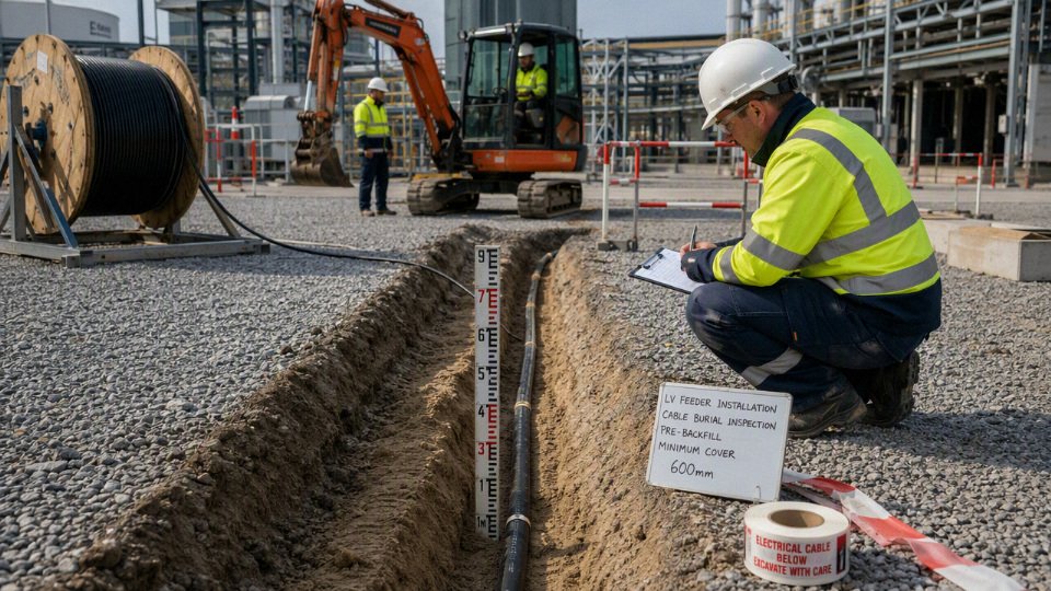
Bury armoured cable too shallow and the first fence post, trenching bucket, or bored drain line can turn a routine yard job into an outage. In a plant, that means locked-out equipment, damaged cable armour, insulation tests, excavation, and production people asking why a “simple” feeder failed. The right burial depth is not just a code number; it is a mix of electrical rules, mechanical protection, route risk, and how the site will be maintained later.
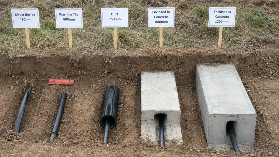
For many low-voltage direct-buried armoured cable runs outside roadways, designers commonly work around 450 to 600 mm of cover, but the legal depth depends on local code, wiring method, circuit rating, surface use, and added protection. Warning tape is typically placed about 150 to 300 mm above the cable or duct.
The awkward part is that “armoured” does not mean “dig-proof.” Steel wire armour helps with mechanical damage and fault return design in the right system, but it does not cancel trench depth, sand bedding, tiles, ducts, route markers, or the need to check the applicable electrical standard before anyone signs off the excavation drawing.
Codes that set depth
Cable burial depth is set by the authority having jurisdiction, the national wiring rules, utility or network-owner requirements, local civil works rules, and the project specification. In practice, the strictest applicable requirement controls, because the installer has to satisfy both legal inspection and the contract documents, not just a rule-of-thumb depth copied from another site.
That distinction matters during procurement. A cable that is perfectly suitable as a product may still be installed wrongly if the trench detail, duct arrangement, warning tape, bedding, route marker, or cover depth does not match the destination country’s rules. For imported armoured cable, buyers should separate two approvals:
- Cable construction approval: conductor, insulation, sheath, armour, voltage rating, fire performance, and certification.
- Installation approval: burial depth, mechanical protection, earthing or bonding method, segregation from other services, route marking, and inspection practice.
United States: NEC Table 300.5 and the AHJ
In the United States, the National Electrical Code does not give one single burial depth for every armoured cable route. NEC Table 300.5 sets required cover based on the wiring method, location, circuit rating, voltage, protection method, and exposure to traffic or buildings.
The word “cover” is worth slowing down on. It usually means the distance from finished grade to the top of the cable, raceway, or enclosure, not the bottom of the trench. If the civil contractor digs 600 mm deep and then places sand bedding, duct, cable, and backfill, the finished cover may be less than expected. I have seen this caught only after the warning tape was already installed and the inspector asked for pothole checks.
Typical NEC Table 300.5 examples run roughly from about 150 to 600 mm of cover depending on conditions, but the exact value must be checked against the current NEC edition and local amendments. The required cover can change with:
- Wiring method: direct-buried cable, rigid metal conduit, intermediate metal conduit, PVC conduit, residential branch-circuit wiring, and other permitted systems are treated differently.
- Location: lawns, landscaped areas, driveways, parking areas, roads, and areas under buildings can have different requirements.
- Circuit voltage and rating: lower-voltage residential circuits with suitable protection may not be treated the same as feeders or higher-energy circuits.
- GFCI protection: in some residential cases, GFCI protection affects the required cover.
- Mechanical protection: a cable in a listed raceway or under a concrete slab is not assessed the same way as a cable placed directly in soil.
- AHJ interpretation: local inspectors may require details that reflect soil conditions, frost depth, future grading, or local utility separation rules.
NEC Table 300.5 gives one universal burial depth for all armoured cable.False
NEC Table 300.5 is arranged by wiring method, circuit conditions, and location. Cover requirements can differ substantially between residential branch circuits, feeders, direct-buried wiring, and raceway systems, and the local authority having jurisdiction may enforce amendments or additional requirements.
For engineers outside the US buying cable for an American project, the practical procurement mistake is ordering cable first and asking trench questions later. The cable type, route, conduit plan, and depth are connected. If the project changes from direct burial to duct because the route crosses a driveway, road, or future equipment pad, pulling tension, bend radius, drum length, duct fill, and termination design may all change.
United Kingdom and BS 7671-based projects
On UK projects, and on many projects influenced by BS 7671, the approach is less about a single universal minimum and more about preventing foreseeable mechanical damage. The installation must be deep enough, protected enough, and marked enough for the conditions likely to occur during the life of the installation.
That is a sensible engineering approach, but it creates procurement ambiguity if the specification is thin. “Install SWA underground” is not a trench design. The route may need suitable bedding, tiles or covers, ducts, warning tape, route markers, or extra protection where it passes under hardstanding, near landscaping, across a yard, or into a building. Common warning tape practice is to place it about 150 to 300 mm above the cable or duct so an excavator or hand-dig crew finds the warning before reaching the live service.
UK distribution network operators, local authorities, rail clients, water companies, and industrial employers may publish their own cable-laying details. These are often more prescriptive than the general wiring rule because they deal with repeat maintenance, public safety, and third-party excavation. A factory extension inside the fence may be inspected as a private electrical installation; a feeder near a public footpath, adopted road, or utility corridor can quickly become a different level of paperwork.
Where BS 7671-style language says “sufficient depth,” the engineering burden shifts onto the designer to show that the route is protected against reasonably expected damage. That may mean accepting a normal building-services trench in a quiet landscaped area, but increasing protection where forklifts, telehandlers, fence-post augers, drainage repairs, or future civils work are likely.
IEC-influenced international projects
IEC standards influence many cable products and installation philosophies, but they do not remove the need to follow the national rules in the country where the cable is installed. On international industrial projects, the actual burial depth is usually defined by a blend of national electrical regulations, utility standards, employer requirements, and the project engineering specification.
This is common on low-voltage, medium-voltage, and plant distribution systems. A low-voltage armoured cable feeding a small pump station may be accepted with ordinary direct burial or ducted burial under the local rule. A medium-voltage feeder to a substation may require a deeper trench, concrete cable tiles, thermal backfill, route markers, spare ducts, separation from instrumentation cables, and controlled crossing details with water, gas, telecoms, or drainage services.
The mechanism is not just bureaucracy. Higher-energy feeders are harder to isolate, more expensive to repair, and more disruptive when damaged. They may also be more sensitive to thermal conditions. Soil thermal resistivity, grouping, duct banks, concrete encasement, and burial depth affect the cable’s ability to shed heat. Putting a cable deeper can reduce accidental strike risk in some locations, but it can also put the cable in warmer or less favorable soil, lengthen repair time, and make fault location and excavation more expensive.
That trade-off is often missed. Deeper is not automatically better. If the site has frequent ground disturbance, deeper cover or concrete protection may be justified. If the site has high load current, grouped circuits, poor soil, or long repair windows, the designer may need ampacity calculations and installation derating before approving a deeper trench.
Other national frameworks and imported cable
Canadian projects may reference the Canadian Electrical Code and provincial enforcement. Australia and New Zealand projects commonly work around AS/NZS wiring rules and local network requirements. Middle Eastern and African projects may use a mix of local law, utility standards, IEC-based specifications, British-influenced practices, American-influenced practices, and employer standards, especially on oil and gas, mining, infrastructure, and large commercial projects.
For technical buyers, the commercial lesson is simple: do not assume that cable accepted in one country is automatically acceptable in another. Confirm the destination requirements before locking the product and installation package. The checks should include:
- Required cable standard and certification.
- Voltage rating and insulation type.
- Armour type and earthing or bonding requirement.
- Fire, smoke, halogen, flame propagation, or CPR-related requirements where applicable.
- Direct burial permission versus mandatory duct installation.
- Minimum cover depth and tolerance after finished grading.
- Bedding material and compaction requirement.
- Separation from power, control, telecoms, gas, water, and drainage.
- Warning tape, cable tiles, marker posts, and as-built survey requirements.
- Special rules for road crossings, rail corridors, classified areas, marine terminals, and public land.
Sites where the specification usually goes beyond normal wiring depth
Utility-owned feeders, public infrastructure, petrochemical plants, mines, airports, ports, and rail projects often impose deeper burial, concrete protection, duct banks, red or yellow marker tape, permanent route markers, and strict as-built documentation. The reason is exposure. These sites see larger excavators, repeated civil works, heavier vehicles, higher fault consequences, and more parties digging near the same corridor.
A normal non-road low-voltage direct-buried armoured cable cover of about 450 to 600 mm may be typical in many locations, subject to code and risk assessment, but that range should not be carried into a refinery road crossing, a mine haul route, an airport apron, or a public utility easement without review. Heavy vehicle loads may require duct encasement or structural protection. Ground movement may require route flexibility or special bedding. Thermal constraints may require wider spacing, selected backfill, larger conductor size, or a different installation method.
A prescriptive code minimum is the starting line, not the whole design. If the route has heavy excavation risk, vehicle loading, unstable ground, high load current, grouped circuits, or poor heat dissipation, the project specification should override a casual minimum-depth habit. If the route is made much deeper without analysis, the plant may buy itself a different problem: harder fault repair, higher outage cost, more difficult future modifications, and possible ampacity penalties that were never included in the cable sizing calculation.
Depth by installation method
The installation method changes both the legal cover requirement and the practical depth you can defend after the cable has been in the ground for ten years. A direct-buried armoured cable, a cable in duct, a concrete-encased duct bank, and a drilled crossing may all carry the same current, but they are exposed to different digging, crushing, water, pulling, and repair risks.
Direct-buried armoured cable
Direct burial is common for low-voltage armoured power circuits where the route is known, future access is unlikely, and the cable construction is rated for contact with soil. In many non-road locations, project practice often lands around 450 to 600 mm of cover for direct-buried low-voltage armoured cable, but that figure only makes sense after checking the local electrical rule, the site risk assessment, and the cable manufacturer’s installation instructions.
Typical candidates include:
- SWA cable, where steel wire armour gives good mechanical protection for multicore low-voltage circuits.
- STA cable, where steel tape armour provides circumferential protection and is often used where the cable design and bending requirements suit it.
- AWA cable, especially for single-core AC circuits where non-magnetic aluminium wire armour avoids excessive armour losses.
- Other armoured and moisture-protected constructions, provided the sheath, bedding, water-blocking, and armour system are specified for direct burial rather than only for tray, duct, or indoor service.
The armour is not a substitute for a proper trench. A direct-buried installation still needs suitable bedding, controlled backfill, route separation, marker tape, and records good enough that someone can find the cable after the foreman who installed it has retired. Sharp stone against the sheath is a slow failure mechanism: traffic vibration, seasonal ground movement, and thermal cycling can make a small pressure point work like a file. Sand or screened bedding is cheap compared with fault location and excavation around a live production area.
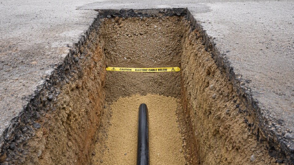
A typical direct-buried build-up would include:
- Excavated trench with stable sides and no standing debris.
- Sand, fine soil, or specified bedding below the cable.
- Cable laid without exceeding minimum bending radius or pulling tension.
- Initial selected backfill around and above the cable.
- Protective board, tile, or slab where required by specification or risk.
- Warning tape commonly placed about 150 to 300 mm above the cable or duct, so an excavator or hand digger finds the warning before reaching the live asset.
- Final backfill, compaction, route markers, and as-built drawings.
Direct burial usually gives the lowest installed material cost, but it gives the poorest future replaceability. That trade-off flips where shutdown cost is high, routes cross operating process areas, or cable replacement would require breaking concrete, stopping traffic, or excavating through other services.
Cable in non-metallic duct
A non-metallic duct does not automatically allow a shallow trench. It adds a replaceable pathway and a useful layer of mechanical protection, but the required cover still depends on the electrical code, soil loading, duct crush rating, traffic exposure, and the likelihood of later excavation.
This is where procurement mistakes start. Someone buys a cable “for duct installation,” the civil crew installs whatever plastic duct is locally available, and the electrical team later discovers the bend radius is too tight or the pulling load is marginal. The duct is part of the cable system, not just a hole in the ground.
For ducted armoured or unarmoured cable routes, check:
- Duct material and stiffness: HDPE, PVC, and other non-metallic ducts vary widely in crush resistance and joint quality.
- Cover depth under load: shallow duct under a driveway or forklift yard can ovalize or crack if it is not selected for the compaction and wheel load.
- Pulling access: long runs need draw pits, manholes, or joint boxes placed by pulling calculation, not by guesswork.
- Bend radius: the duct route must respect the cable’s installed bending radius, including sweeps at entries and exits.
- Water management: buried ducts often collect water. The cable sheath and accessories must tolerate that environment.
- Identification: spare ducts need caps, draw ropes, records, and labeling, otherwise they become expensive mysteries.
The mechanism is straightforward: duct friction increases pulling tension, bends multiply sidewall pressure, and water sitting in the duct changes the long-term sheath and accessory environment. A cable that would sit happily in a well-bedded direct-burial trench may be damaged during installation if pulled through a poor duct route with tight sweeps and no lubricant plan.
Rigid metal conduit and heavy mechanical protection
Some codes permit reduced cover for certain rigid metal conduit or other heavy protective wiring methods, but the reduction is conditional. It may depend on voltage, circuit rating, location, corrosion protection, ground-fault protection, physical damage exposure, and whether the installation is under a building, driveway, landscape area, or public route.
Do not lift a reduced-cover number from one code table and use it on every project. NEC Table 300.5, for example, includes cover values that can range roughly from 150 to 600 mm depending on wiring method, circuit type, protection, and location. That is a code-specific example, not a universal permission slip.
Rigid metal conduit is useful where the route is short, damage exposure is high, and the cost of fittings and corrosion control is justified. Around building entries, generator pads, loading bays, and exposed risers, it can be the right answer. For long buried feeder routes, it becomes expensive, harder to pull, and more sensitive to corrosion, coating damage, threaded joint quality, and bonding details. Anyone who has watched a crew fight a long pull through too many rigid elbows knows the “stronger” method can create its own installation risk.
Concrete-encased duct banks
Concrete-encased duct banks are used where the cable route is strategic enough to deserve civil infrastructure: industrial plants, substations, road crossings, ports, airports, rail facilities, utility corridors, and high-reliability plant feeders. The concrete protects the ducts, maintains alignment, and gives a durable corridor that can carry multiple circuits and spares.
The design is more than “ducts in concrete.” It should define:
| Design item | Why it affects depth and installation quality |
|---|---|
| Duct spacing | Controls pulling clearance, heat dissipation, and constructability during the pour. |
| Thermal environment | Concrete, soil, circuit grouping, and load factor affect cable ampacity; deeper is not always thermally better. |
| Spare ducts | Low-cost during construction, expensive or impossible after the slab, road, or plant area is operating. |
| Pull boxes and manholes | Set maximum pulling lengths and provide access for testing, repairs, and future circuits. |
| Drainage and slope | Reduces standing water problems in ducts and chambers, though many systems must still be treated as wet locations. |
| Reinforcement and civil loading | Needed where traffic, settlement, or poor ground could crack the encasement. |
| Separation from other utilities | Avoids heat interaction, induced effects, maintenance conflicts, and unsafe excavation interfaces. |
The thermal trade-off is often missed. Concrete gives mechanical strength and route discipline, but grouped loaded cables in an encased bank can run hotter than the same circuits separated in soil. If ampacity is tight, the route design may force a larger conductor, fewer loaded circuits per bank, larger spacing, or a different installation method. The preferred answer stops holding when the limiting factor is not mechanical damage but heat rejection.
Protective tiles, slabs, covers, or boards
Protective covers are not there to make a bad trench good; they are there to add a sacrificial impact barrier and a visible warning layer above the cable or duct. They are especially useful where full depth is constrained by bedrock, existing utilities, foundations, drainage structures, contaminated ground caps, or old plant areas where every excavation finds something unexpected.
Common options include concrete tiles, polymer cable covers, warning boards, steel plates in special cases, or site-specified protective slabs. Their value is practical: a shovel, pick, or small excavator bucket hits the cover before it hits the cable. The cover also tells the person digging that the red or yellow tape was not just construction rubbish blown into the trench.
Where depth is reduced because the site physically will not allow the preferred cover, get that decision approved through the project authority and local code process. The detail should show the actual cover depth, protection type, warning layer, cable spacing, and limits of the reduced-depth zone. “We could not dig deeper” is not a technical specification.
Trenchless or directional drilling routes
Directional drilling routes must be engineered from the bore profile, not copied from open-trench depth practice. Minimum cover is only one variable; the more common failure points are bend radius, pulling tension, duct collapse, bore path uncertainty, and damage at entry and exit pits.
A drilled crossing under a road, railway, watercourse, or operating yard usually needs:
- Surveyed existing utilities and agreed clearance envelopes.
- Bore profile showing depth, radius, entry angle, and exit angle.
- Duct material selected for pullback load, soil conditions, and long-term pressure.
- Cable pulling calculation after the duct is installed, not just before.
- Allowance for duct ovality, mud, water, and internal debris.
- Pits large enough to handle cable drums, winches, rollers, and safe bending radius.
- A method to verify duct continuity before the cable is committed.
The temptation is to say, “The bore is deeper, so it must be safer.” Sometimes yes. But a deep bore with aggressive curvature can damage a large armoured cable during pull-in, while a shallower open trench with good protection may be electrically and mechanically cleaner.
Building entries, risers, and crossings
The straight trench is usually not where cables get abused. Damage often happens at transitions: out of the ground into a wall, cabinet, pole, transformer plinth, motor control center, or outdoor equipment skid. These points see settlement, mower strikes, pallet truck contact, forklift nudges, UV exposure, water tracking, and maintenance crews leaning ladders where they should not.
Use extra mechanical protection at:
- Building penetrations and sleeves.
- Vertical risers on poles, walls, and equipment frames.
- Cabinet and kiosk entries.
- Transformer and generator pads.
- Areas exposed to forklifts, trucks, mowers, livestock, or public access.
- Points where underground duct changes to tray, ladder, or gland plate entry.
Road, driveway, and yard crossings deserve the same discipline. Depth and protection often increase because wheel loads, compaction, future resurfacing, drainage work, and maintenance excavation are predictable risks, not surprises. In a plant yard, the “temporary” crane route has a habit of becoming permanent after the first shutdown.
The installation method should be chosen before the cable is ordered. Sheath material, armour type, water blocking, drum length, pulling calculation, gland and termination kit selection, duct size, spare capacity, and even factory test documentation all depend on the route design. If the procurement package only says “armoured cable for underground use,” the buyer may get a cable that is electrically correct but awkward, expensive, or risky to install on the actual route.
Site loading and ground risks
Increase burial depth, or add mechanical protection, where the ground is likely to be cut, crushed, resurfaced, settled, flooded, or chemically aggressive. The mistake is treating depth as the only defence: in many sites, bedding quality, warning tape, duct strength, separation from other services, joint location, and route records do more to prevent failures than another 150 mm of cover.
Deeper burial is not automatically safer for armoured cable.True
Greater cover can reduce accidental shallow strikes, but it can also increase excavation cost, slow fault repair, complicate pulling through ducts, affect current rating through poorer heat dissipation, and make route verification harder if records are weak.
Typical site risks and what they change
| Site condition | Main risk to the cable | Practical design response |
|---|---|---|
| Pedestrian landscaping and gardens | Spades, tree planting, fence posts, irrigation repairs, unrecorded small works | Keep the route visible in records, use warning tape, consider duct or tiles near planting zones |
| Driveways, car parks, and roads | Wheel loads, compaction, resurfacing, kerb work, drainage cuts | Higher cover, stronger duct or concrete protection, careful reinstatement specification |
| Industrial yards and warehouses | Forklifts, mobile cranes, containers, HGVs, repeated ground modification | Treat the route like plant infrastructure, not landscaping; allow for future slab cutting and expansion |
| Agricultural and rural land | Ploughing, mole drainage, fence posts, irrigation, long routes with few landmarks | Depth alone may not be enough; use route markers, GPS records, warning tape, and protection at crossings |
| Rocky or contaminated soil | Sheath abrasion, corrosion, point loading, chemical attack | Select bedding, sheath type, corrosion protection, and route protection before arguing over millimetres |
| Wet or flood-prone ground | Water ingress at damage points, duct flooding, joint deterioration | Use suitable water resistance, place joints out of wet zones where possible, test insulation after installation |
Pedestrian routes are lightly loaded, not low-risk
Garden paths, landscaped areas, and public footways usually see modest mechanical loading compared with roads, so the structural case for very deep burial is weaker. The nuisance is maintenance activity: a fencing contractor with an auger, someone relocating irrigation pipe, a landscaper planting semi-mature trees, or a caretaker digging without drawings. I have seen more near misses from tidy little hand excavations than from dramatic construction work.
For these routes, a practical protection package usually includes:
- Suitable cover in line with local code and project specification.
- Sand or selected bedding to prevent stones bearing into the sheath.
- Warning tape about 150 to 300 mm above the cable or duct, positioned so it is found before the cable.
- Cable tiles, covers, or ducting where planting, fencing, or irrigation work is likely.
- Accurate route records tied to fixed landmarks, not just “runs beside the hedge,” because hedges move or disappear.
The risk flips when the landscaping route becomes a future building route. If the owner may add gates, lighting columns, drainage, or a vehicle crossing later, design it closer to a utility corridor than a flowerbed.
Roads, yards, and warehouses need protection against the work done after installation
Driveways, car parks, estate roads, loading bays, and industrial yards justify higher cover or stronger protection because the cable is exposed to repeated surface loading and later civil works. Wheel loads do not act on the cable as a neat vertical force; they spread through the pavement, sub-base, and backfill. Poor compaction, soft patches, and voids concentrate stress. A shallow duct under a repaired pothole can end up taking abuse it was never intended to carry.
Road and yard routes should be checked against:
- Vehicle type: cars, vans, HGVs, forklifts, reach stackers, mobile cranes, container handlers.
- Pavement build-up: asphalt, concrete slab, block paving, hardcore, temporary road plates.
- Future work: resurfacing, kerb replacement, drainage channels, barrier posts, weighbridge pits.
- Repair access: whether the route can be isolated and excavated without shutting the entrance or loading dock.
- Duct crush rating and installation method, verified against supplier data and local specification.
Industrial warehouses bring another awkward detail: the ground plan keeps changing. A yard that handles pallets today may receive containers next year. A slab that looks permanent may be saw-cut for a new dock leveller, fire main, or automation project. In these environments, the best route is often not the shortest route. It is the route least likely to be attacked by future projects.
Agricultural and rural routes need landmarks and tolerance for rough ground
Rural cable runs often look simple on a drawing and become difficult in the field. There may be ploughing, subsoiling, mole drainage, trenching for field drains, fence posts, stock water pipes, irrigation lines, and livestock infrastructure. Rocks move upward in some soils over time, and long runs across open land may have few permanent reference points.
Deeper burial can help under cultivated ground, but it does not solve route management. Put warning tape in consistently, use marker posts where acceptable, record GPS coordinates, and protect high-risk crossings such as tracks, gateways, ditches, and fence lines. Where agricultural equipment may disturb the ground deeply, the required depth and protection should be agreed with the landowner and checked against local utility practice, not assumed from a domestic garden detail.
Soil, water, and temperature can override the nominal depth
Rocky ground needs selected bedding because armour and outer sheath can be damaged by point contact during backfill compaction. Corrosive or contaminated soil raises different questions: sheath material, armour corrosion protection, chemical compatibility, and whether the cable should be installed in duct or with a protective surround. In aggressive ground, an extra 100 mm of depth does very little if the cable is sitting against sharp rubble or chemically active fill.
Wet ground and high water tables need the same practical discipline. The cable construction must be suitable for the exposure, and any longitudinal water blocking or sheath integrity requirement should be specified before procurement. Ducts in wet ground often become water pipes unless drainage and sealing are designed properly. Joints should be kept out of low points and flood zones where possible; if that is impossible, the jointing system, enclosure rating, installation workmanship, and post-installation insulation testing become critical.
Thermal conditions are the counter-intuitive part. Deeper soil is often cooler and more stable seasonally, which can help in hot climates or sun-baked surfaces. But ampacity depends on the full heat path from conductor to surrounding soil. Dry, high-resistivity soil, tightly grouped circuits, duct banks, concrete encasement, and sustained load can trap heat. A deeper cable may be mechanically safer but electrically less forgiving if the thermal design is poor. This is where load profile, soil thermal resistivity, grouping factors, and installation drawings matter more than a rule-of-thumb depth.
Existing utilities, frost, and settlement set practical limits
Cable routes also need separation from gas, water, telecoms, steam lines, process pipework, and other power circuits. Minimum distances depend on local rules and the utility owner’s requirements, so they must be verified on the actual project. Crossings are usually cleaner at near-right angles, with protective barriers or sleeves where separation cannot be maintained. Steam and hot process lines deserve special attention because they create both thermal derating and sheath ageing concerns.
Freezing, thawing, subsidence, and poor backfill compaction can strain cables, ducts, and joints. Frost heave can move shallow installations; settlement can pull on ducts entering buildings or chambers. A nice straight trench on installation day can become a tensioned system after one winter if the backfill was dumped in wet and never compacted properly.
The practical boundary is this: increasing depth is useful only while the installation remains installable, inspectable, thermally acceptable, and repairable. Past that point, the better engineering answer is usually route change, duct selection, bedding improvement, concrete or tile protection, better joint placement, or tighter excavation control. The drawings and as-built records then need to be good enough that the next crew with a mini-excavator can actually find the cable before they find it the expensive way.
Cable construction choices
A sensible burial depth only works if the cable itself is built for the route. For underground service, specify the armour type, sheath compound, water protection, fault-duty capability, and termination system as one package, not as separate purchasing lines. Armour can reduce mechanical damage risk, but it does not automatically make a cable suitable for direct burial, wet ducts, high fault current, or poor civil work.
Steel wire armoured cable
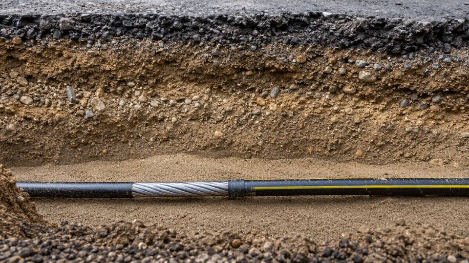
Steel wire armoured cable is a common choice for low-voltage multicore underground feeders, submains, pump supplies, lighting circuits, and plant distribution runs. The wire armour gives useful impact and crush resistance during backfilling, minor ground movement, and later excavation mistakes, especially where the route crosses compacted yard areas or service corridors.
The part that gets missed in weak specifications is the electrical role of the armour. In many installations the armour is not just mechanical protection; it may also form part of the protective earthing path. That means the designer has to coordinate:
- Armour bonding arrangement at one end or both ends, depending on the earthing design and induced voltage concerns
- Gland type, gland material, shrouds, earth tags, banjos, and bonding jumpers
- Prospective earth fault current and disconnection time
- Armour cross-sectional area and short-circuit withstand
- Corrosion protection at terminations, especially in wet chambers or coastal sites
- Compatibility between cable outer diameter and certified gland size
I have seen perfectly good cable compromised by cheap glands, missing serrated washers, or paint left under an earth tag. The trench depth did nothing wrong; the fault path did.
Steel tape armoured cable
Steel tape armour is often specified where radial crush protection matters more than tensile flexibility. It can be a good fit for buried distribution routes, industrial sites, and places where the cable is laid in a controlled trench rather than pulled hard through a winding duct system.
The trade-off is handling. Tape armour generally does not behave like wire armour when bent, pulled, or dressed into a termination box. It can be less forgiving around tight bends, changes in level, and congested switchroom entries. If the route has multiple sweeps, duct entries, or awkward risers, check the manufacturer’s minimum bending radius and pulling method before treating tape armour as a stronger version of wire armour. It is different, not simply “heavier duty.”
Aluminium wire armoured cable
For single-core AC circuits, aluminium wire armour is commonly used because it is non-magnetic. That matters because ferromagnetic armour around a single-core AC cable can suffer from induced circulating currents and magnetic losses, creating unwanted heating and reducing usable current capacity.
This is one of those details that separates a workable design from a hot cable tray or an overloaded trench. In three-core cable, the magnetic fields are more balanced inside the same cable construction. In single-core circuits, each phase is physically separate, so armour material, bonding method, phase spacing, and trefoil or flat formation all affect losses and temperature. The preferred design can flip if the installation changes from three-core LV distribution to large single-core feeders for a transformer or drive system.
Medium-voltage armoured cable
Medium-voltage underground cable needs a much tighter specification than low-voltage armoured power cable. Burial depth and armour are only part of the system; the insulation design, screen construction, water protection, test regime, and accessories become just as important.
A proper MV cable enquiry should define or request confirmation on:
- Rated voltage and system earthing arrangement
- XLPE or other approved insulation system
- Conductor screen and insulation screen construction
- Metallic screen type and short-circuit rating
- Armour material and whether it is magnetic or non-magnetic
- Longitudinal and radial water blocking requirements
- Outer sheath compound and oversheath testing requirements
- Partial discharge testing requirements
- Routine and type test references from the applicable standard
- Approved terminations, joints, separable connectors, and gland plates
- Utility, mine, port, data centre, or industrial owner approval requirements
MV failures are expensive because the repair is rarely just “dig and join.” Fault location, switching, outage planning, joint bay access, testing, and recommissioning can dominate the cost. A cable that looks cheaper per metre can be a poor buy if the screen rating, water blocking, or accessory approval does not match the network.
Outer sheath selection
The outer sheath is the cable’s first chemical and environmental defence. It also affects pulling friction, abrasion resistance, fire behaviour, sunlight exposure, and sometimes rodent or termite resistance.
| Sheath or property | Where it is usually considered | Practical caution |
|---|---|---|
| PVC | General low-voltage power distribution, many buried and indoor-outdoor routes | Economical and widely used, but check temperature, oil, chemical, and fire requirements |
| PE | Wet ground, ducts, abrasion-prone pulling, routes needing stronger moisture resistance | Often tougher against moisture, but fire performance may be unsuitable in enclosed fire zones |
| LSZH | Tunnels, buildings, public infrastructure, enclosed plant areas | Good where smoke and acid gas limits matter; soil and UV suitability still need confirmation |
| Flame-retardant sheath | Cable basements, substations, process buildings | Flame performance does not automatically mean direct-burial or chemical resistance |
| Oil-resistant sheath | Workshops, refineries, fuel handling, generator areas | Specify the actual oil or hydrocarbon exposure where possible |
| UV-resistant sheath | Exposed risers, tray sections before burial, solar or outdoor plant | Needed where cable is not fully buried or protected from sunlight |
| Anti-termite sheath | Tropical sites, plantations, remote substations, known termite regions | Should be specified from project conditions, not assumed from armour |
| Chemical-resistant sheath | Contaminated soil, process areas, wastewater, landfill or industrial brownfield routes | Requires soil or chemical data; generic “chemical resistant” wording is too loose |
A small exposed section can drive the sheath choice for the whole route. For example, a buried feeder that rises up a wall into a switchboard may need UV resistance, suitable cleats, and mechanical guarding even if 95% of the run is underground.
Direct burial rating and water blocking
Any armoured cable can be buried directly if it is installed deep enough.False
Direct-burial suitability depends on the cable standard, sheath, armour corrosion protection, moisture resistance, bedding, soil chemistry, mechanical risk, and manufacturer rating. Depth alone cannot correct a cable construction that is not approved for the installation environment.
Direct burial needs to be stated or supported in the datasheet, standard, or project specification. The buyer should check whether the cable is intended for direct contact with soil, installation in ducts, installation on tray, or protected installation only. Those categories are not interchangeable.
Water-blocked designs are justified where water presence is likely and failure consequence is high. Typical cases include:
- Long feeder routes where water migration could affect a large cable length
- Flood-prone substations, ports, mines, and low-lying industrial sites
- Duct systems that hold standing water because drainage was never built or has silted up
- Critical loads where outage cost is far higher than the cable premium
- Medium-voltage circuits where moisture ingress can accelerate insulation system failure
Longitudinal water blocking limits water travel along the cable. Radial water protection reduces ingress through the sheath system. The mechanism is simple enough: once water enters at a sheath defect or damaged termination, capillary paths and conductor interstices can carry it far from the original damage point. Blocking materials slow that migration, giving maintenance crews a fighting chance to isolate the affected section rather than replacing a long route.
Mechanical protection versus electrical performance
More protection is not free. Armour, ducting, deeper burial, and concrete covers can all change cable thermal performance, installation stress, and maintainability. A cable in free-draining selected sand may run cooler than the same cable buried deep in dry, compacted, high-thermal-resistivity soil or crowded into a duct bank with other loaded feeders.
Check these limits before freezing the purchase order:
- Current rating after applying soil temperature, burial depth, grouping, duct, and thermal resistivity factors
- Minimum bending radius during installation and final set
- Maximum pulling tension, sidewall pressure, and pulling eye method
- Short-circuit withstand of conductor, screen, and armour
- Gland, termination, lug, joint, and enclosure compatibility
- Allowable sheath test voltage and test method after installation
- Corrosion risk from soil, stray currents, and dissimilar metals at glands or support steel
Choosing heavier armour may reduce one damage mode while making installation harder, hotter, or less compatible with the termination hardware. It will not fix a route with sharp bends, rubble backfill, missing warning tape, uncontrolled excavator access, or no as-built records. The reliable underground cable system is built from matched decisions: correct cable construction, suitable depth, clean bedding, warning systems, civil protection where needed, and terminations installed by people who understand the cable they are cutting into.
Trench detailing and protection
Installation sequence and quality checklist
- Pre-excavation survey
- Confirm the applicable permit, excavation notice, and authority having jurisdiction requirements before a bucket goes in the ground. On many sites the electrical code is only one layer; the road authority, utility owner, port operator, rail operator, or industrial client may impose stricter cover, marker, and reinstatement rules.
- Review issued-for-construction drawings against the latest underground utility records. Do not trust old plot plans without field verification; abandoned water lines and “temporary” site power routes have a way of becoming permanent hazards.
- Carry out utility locating using the methods accepted locally: electromagnetic locating, ground-penetrating radar where useful, record tracing, and hand-dug or vacuum-excavated trial holes at crossings and congested areas.
- Walk the route with electrical, civil, safety, and operations people. The maintenance supervisor often knows about buried drains, old foundations, or forklift routes that never made it into the drawing package.
- Freeze the agreed excavation limits, required cover, separation distances, test hold points, and backfill material requirements before procurement and installation crews are released.
- Route setting-out
- Mark the cable corridor clearly with paint, pins, stakes, or survey offsets that survive normal site traffic. A single painted line is rarely enough where the trench has width, bends, joint bays, or parallel circuits.
- Keep the route as straight as the site allows. Every unnecessary bend increases pulling load, sidewall pressure, installation time, and the chance of armour distortion.
- Plan joint bays, draw pits, duct chambers, or pulling points where they can actually be accessed later. A joint under a future concrete apron or behind a pipe rack leg is a maintenance problem waiting to happen.
- Protect future maintenance corridors. Leave space for excavation plant, isolation barriers, drainage reinstatement, and safe access, not just the cable itself.
- Trench excavation
- Excavate to a depth that provides the specified cover after bedding, cable diameter, protective covers, backfill settlement, and final grading are accounted for. Cover should be measured from the finished surface level, not from the temporary ground level on the day the trench is open.
- Set trench width wide enough for bedding placement, cable spacing, rollers if used, and safe compaction beside the cable. A trench that is too narrow forces installers to drag the cable along the sidewall, which is where sheath cuts and armour scuffing start.
- Control side stability in line with the soil and local safety rules. Benching, shoring, trench boxes, or exclusion zones may be needed; no cable installation schedule justifies men working under a loose vertical wall.
- Manage water before cable laying. Dewatering may be as simple as a sump pump in sandy ground or as formal as well points on a deep project. Muddy bedding cannot be compacted properly, and floating ducts or displaced warning tape can ruin an otherwise tidy installation.
- Keep excavated spoil away from the trench edge and separate unsuitable material from reusable backfill. Broken concrete, weld rod stubs, rebar offcuts, flint, slag, and sharp rock should not migrate back into the cable surround.
- Bedding layer
- Place a selected bedding layer under the cable: washed sand, screened fine soil, or another approved material from the project specification. The purpose is not cosmetic. Bedding spreads load, removes point contact, and prevents the outer sheath from bearing directly on stones, clinker, sharp fill, or trench irregularities.
- Maintain bedding thickness consistently through dips, crossings, and joint areas. Thin spots matter because a cable under compacted backfill behaves like a loaded cylinder; one hard point can create local sheath stress, especially after settlement or traffic vibration.
- Avoid chemically aggressive or contaminated bedding unless it has been assessed for compatibility with the sheath and armour protection system. Industrial sites with ash, hydrocarbons, acids, or saline fill deserve extra caution.
- Cable laying or pulling
- Check the cable drum before unloading: correct cable, drum direction, end caps intact, no crushed lagging, no water ingress, no visible sheath cuts. Store drums upright on firm ground and roll only in the marked direction.
- Observe the manufacturer’s minimum bending radius. This applies during pulling, training into a trench, jointing, and final positioning; a cable can be damaged even if the finished bend looks acceptable.
- Control maximum pulling tension and sidewall pressure, especially through bends, ducts, and long routes. Pulling on conductors, armour, or a pulling stocking must follow the cable supplier’s method statement. If the calculated force is marginal, add rollers, reduce bend severity, install a draw pit, or pull from the opposite end.
- Use trench rollers, corner rollers, bellmouths, and clean duct entries. Do not let the cable scrape over trench edges, road plates, manhole lips, or a loader bucket used as a “temporary guide.”
- Respect installation temperature limits from the cable data sheet. Cold sheaths are less forgiving; in winter work, a cable that handled well in the yard may become stiff enough to kink during placement.
- Watch for twist and armour deformation. If the cable begins to corkscrew off the drum, stop and correct the pay-off arrangement rather than forcing it into the trench.
- Separation and grouping
- Maintain specified spacing between:
- Parallel power circuits
- Multiple loaded cables in the same trench
- Communication, control, instrumentation, or data cables
- Metallic water, gas, steam, and process pipes
- Drainage lines and services likely to be excavated later
- Earthing conductors, cathodic protection systems, and lightning protection routes where interference or corrosion studies apply
- Spacing is not only about neatness. Closely grouped power cables run warmer because each circuit adds heat to the same soil volume; that can reduce ampacity unless the design has accounted for soil thermal resistivity, load profile, grouping factor, and backfill material. The trade-off is land use: wider spacing improves thermal and maintenance conditions, but increases trench width, reinstatement cost, and conflict with other services. The preferred choice flips on congested sites, where ducts, engineered thermal backfill, or rerouting may be cheaper than fighting for a wide open trench.
- Maintain specified spacing between:
- Warning tape and marker systems
- Install warning tape above the cable or duct where it will be found before the cable is reached by normal excavation. Common practice is roughly 150 to 300 mm above the service, but the project specification and local utility rules take priority.
- Use detectable tape where future locating from the surface is required, especially for non-metallic ducts or complex corridors. Non-detectable tape is cheaper, but it relies on someone already digging in the right place.
- Add surface markers, route posts, engraved plates, kerb marks, or electronic markers at changes of direction, joints, road crossings, and critical service corridors. In paved industrial areas, I prefer marker details that maintenance crews can still read after resurfacing, not just pretty route posts that disappear after the first civil works package.
Warning tape should normally be placed above the cable or duct, not directly on it, so an excavator or hand-digging crew encounters the warning before reaching the live service.True
The exact depth is set by local rules and the project specification, but the protection principle is established practice: the tape is an early warning layer, not a mechanical shield.
- Mechanical covers
- Use cable tiles, polymer boards, concrete slabs, steel plates, duct covers, or concrete encasement where shallow burial, traffic loading, frequent future excavation, or crossing risk justifies it.
- Mechanical protection changes the risk profile, but it is not a license to ignore code cover unless the authority and specification allow that arrangement. A slab can spread a digger tooth load or vehicle wheel load, yet it can also complicate heat dissipation and future repairs.
- Mark the protection system in the as-built records. Unrecorded concrete over a cable may protect it today and create a demolition surprise ten years later.
- Backfill and compaction
- Backfill in stages:
- Selected bedding below the cable
- Selected surround above and around the cable
- Warning tape layer at the specified height
- General backfill only after sharp material is removed
- Final reinstatement to the finished surface profile
- Compact carefully beside and above the cable. Heavy compactors used too early can displace cables, crack ducts, damage tiles, or squeeze bedding away from the service. Light hand compaction or small plate compactors are usually used near the cable, with heavier compaction higher up where cover is adequate and the specification permits it.
- Allow for settlement, especially in landscaped areas, road shoulders, and trenches cut through made ground. If the finished surface sinks later, the cable cover reduces with it; if the area is raised by later works, access depth and thermal assumptions may change.
- Backfill in stages:
- Testing and records
- Complete inspection and testing at agreed hold points, not only after the trench has disappeared. Typical records include:
- Insulation resistance test results
- Continuity checks
- Sheath integrity testing where applicable to the cable design
- Armour bonding and earthing checks
- Phase identification and core marking
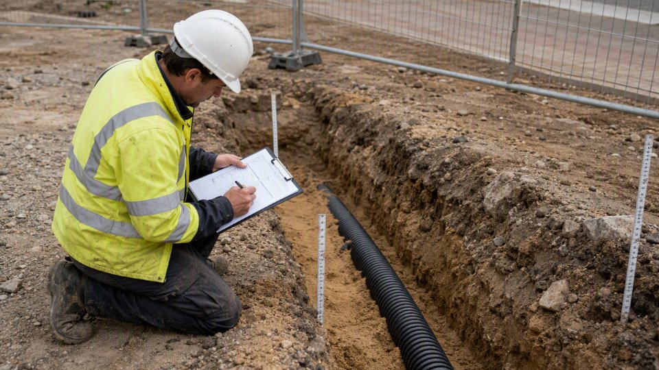
- Cable route photos before backfill, with scale or survey reference
- Joint and termination records
- As-built drawings showing depth, offsets, joints, ducts, crossings, and spare ways
- GPS or surveyed coordinates where the client requires them
- Commissioning documents and test certificates
- Photographs before backfill are cheap insurance. Take them looking both directions, include fixed references, and capture tape, covers, bedding, crossings, and joint bays. Once the trench is closed, the as-built record becomes part of the cable protection system. If it is vague, missing, or filed where maintenance cannot find it, the next excavation crew is working half blind.
- Complete inspection and testing at agreed hold points, not only after the trench has disappeared. Typical records include:
Procurement data for suppliers
A useful cable quotation starts with duty, route, environment, and documentation requirements, not just “armoured cable, 600 mm deep.” The supplier needs enough data to check ampacity, voltage drop, short-circuit withstand, sheath and armour suitability, drum planning, accessories, and certification before price and delivery promises mean much.
A supplier cannot responsibly confirm an underground armoured cable specification from burial depth alone.True
Cable rating, armour selection, sheath material, accessories, drum lengths, and documentation depend on electrical duty, route geometry, soil conditions, mechanical risk, and the governing standard or project specification.
For bulk procurement, I would send the supplier a route schedule and a single-line diagram before asking for final commercial terms. A half-page enquiry often turns into three weeks of clarification, especially when drums arrive on site and someone discovers the longest pull section is 420 m with four bends and no room for a joint bay.
Electrical data
Provide the electrical basis first, because it drives conductor size, insulation grade, armour bonding, and fault rating:
- Voltage grade and system type, such as low-voltage distribution, medium-voltage feeder, three-phase four-wire, or DC.
- System earthing method, including TN, TT, IT, solidly earthed, resistance earthed, or utility-specific arrangement.
- Number of cores, neutral requirement, protective conductor arrangement, and whether armour is used as a CPC or only mechanical protection.
- Conductor material, usually copper or aluminium, and any project preference for compacted or sector-shaped conductors.
- Conductor size, design load current, diversity assumptions, and future spare capacity allowance.
- Prospective fault level and short-circuit duration at the cable origin.
- Permitted voltage drop from source to load, including motor-starting or long-feeder conditions where relevant.
The mechanism is simple but often missed: burial conditions affect heat rejection, heat affects conductor operating temperature, and conductor temperature affects both ampacity and insulation life. A larger conductor may solve voltage drop and thermal margin, but it increases cable diameter, bending radius, drum weight, pulling tension, gland size, and termination space. The preferred choice flips when civil works or pulling access become the constraint rather than the copper or aluminium cost.
Installation and route data
Give the route as it will actually be built, not as a straight-line distance on a layout drawing:
- Specified burial depth or cover, with the governing code or project standard.
- Direct burial, ducted installation, conduit, trough, concrete encasement, or mixed route.
- Open trench, horizontal directional drilling, road crossing sleeve, cable ladder transition, or vertical riser.
- Total route length, measured cable length, spare allowance, and elevation changes.
- Number of bends, bend radius limits, pulling sections, winch access points, and intended pulling direction.
- Joint positions, joint bay dimensions, and any “no joint” zones under roads, process areas, or security fencing.
- Maximum drum diameter, drum width, drum weight, unloading method, and site storage limits.
For procurement, drum planning is not a warehouse detail; it is part of the installation design. A supplier can manufacture a long continuous length, but the site may not be able to unload it, turn it, pull it, or store it safely. Give forklift capacity, crane availability, access road condition, and any seasonal restrictions; muddy access tracks have ruined more schedules than cable factories have.
Environmental and mechanical risk data
The supplier should know the soil and exposure conditions before selecting sheath materials and construction details:
- Soil thermal resistivity, or at least soil type, moisture pattern, backfill specification, and whether thermal sand is planned.
- Ambient air temperature, ground temperature, grouping with other circuits, and expected load profile.
- Standing water, flood exposure, high water table, salt, hydrocarbons, solvents, fertilizers, acids, alkalis, or other contaminants.
- UV exposure at risers, outdoor terminations, and tray transitions.
- Termite, rodent, or other pest risk.
- Fire performance requirements in tunnels, substations, buildings, escape routes, or utility galleries.
- Traffic loading, cranes, forklifts, tracked vehicles, railway proximity, agricultural ripping, future excavation, rock, settlement, slope movement, or seismic movement.
A deeper trench does not automatically compensate for poor soil, heavy traffic, or repeated excavation. In practice, added protection may mean ducts, slabs, concrete cover, marker tape, route markers, or a different installation corridor. Warning tape is commonly placed roughly 150 to 300 mm above the cable or duct so the excavator finds the warning before the cable, but the actual placement must match the project specification.
Standards, certification, accessories, and project documents
State the required compliance route clearly. Depending on country and owner, the enquiry may refer to IEC, BS, EN, NEC-related project specifications, utility standards, national approvals, marine or industrial specifications, or buyer-specific test plans. Ask for the documentation package in the required language and format:
- Type test references, routine test certificates, and factory test records.
- Third-party inspection requirements and inspection hold points.
- Cable datasheets, construction drawings, dimensional drawings, packing lists, and drum schedules.
- Batch traceability, marking requirements, metre marking, and project tag numbers.
- Export documents, certificates of origin where needed, and shipping marks.
Coordinate accessories at the same time as the cable. Glands, lugs, joints, terminations, cleats, earthing kits, duct seals, pulling eyes, and sheath repair kits must suit the cable’s conductor shape, armour type, outer sheath diameter, bonding method, voltage class, and installation environment. I have seen perfectly good cable delayed because the gland kit was sized from a catalogue diameter instead of the approved manufacturing drawing.
An integrated manufacturer such as Jinda can support R&D, production, technical review, bulk supply, project documentation, and after-sales service when the buyer provides complete route and performance data. That does not replace the local code authority or project engineer, but it does let the supplier check manufacturability, propose suitable cable construction, plan drums, prepare factory tests, and keep documentation aligned with the procurement package.
Frequently asked questions
How deep should armoured cable be buried?
For many low-voltage, direct-buried armoured cable routes outside roads, practical cover often lands around 450 to 600 mm, but that is not a universal rule. The correct depth depends on the local code, installation method, voltage, soil conditions, likely digging activity, and whether extra protection such as duct, conduit, tiles, or concrete is used.
Is there one legal depth for every country?
No. Burial depth is set by the authority and standard system that governs the project, not by the cable type alone. A project may be controlled by a national wiring code, utility standard, industrial client specification, railway or airport rule, or municipal permit condition.
There is no single legal burial depth for armoured cable that applies in every country and every site condition.True
Depth requirements vary by jurisdiction, voltage, wiring method, location, mechanical protection, and site use. For example, NEC Table 300.5 gives different cover values depending on circuit and installation conditions rather than one fixed value.
Can armoured cable be buried without conduit?
Yes, if the cable is specifically suitable for direct burial and the local code allows that installation method. Steel wire armour helps with mechanical protection, but it does not make every cable suitable for wet soil, chemical exposure, termite risk, repeated ground movement, or poor bedding.
Ducts, conduit, or extra mechanical protection are usually better where:
- Future replacement is likely.
- The route crosses paved areas.
- The soil contains rubble, slag, sharp rock, or demolition waste.
- The cable passes under traffic, gates, yards, or loading zones.
- The client wants easier inspection records and route management.
How deep should cable be under a garden?
Garden routes are usually lower-load areas, so they often use the lower end of normal non-road burial practice where local rules allow it. The trap is future disturbance: fence posts, irrigation work, tree planting, edging, and enthusiastic weekend digging all create strike risk.
For a private garden or landscaped strip, I would still want clear route marking, warning tape roughly 150 to 300 mm above the cable or duct, and a route drawing that someone can find five years later. A shallow cable in soft topsoil is easy to hit with a spade.
How deep should cable be under a driveway?
Driveways normally justify greater cover or stronger protection than a lawn because they see wheel loads, compaction, resurfacing, and occasional excavation. Even light vehicles create repeated stress paths through the pavement and sub-base, especially near edges where contractors later cut channels for drains or gates.
In practice, a driveway cable is commonly installed in duct or conduit, with bedding and backfill selected to avoid point loading. The final depth should be checked against the local electrical code and any civil specification for the pavement.
Does steel wire armour replace warning tape?
No. Armour is the last line of mechanical defence, not a permission slip to skip route controls. Warning tape, marker posts where appropriate, as-built drawings, cable location before digging, and permit-to-excavate procedures still matter.
A digger bucket will not politely stop because the cable has armour. It may deform the sheath, expose steel wires, damage insulation, or create a fault that appears only after moisture gets in.
Is depth measured to the top or bottom of the cable?
Cover is normally measured from finished ground level to the top of the cable, duct, conduit, or protective system, depending on how the rule is written. Finished ground level matters; measuring before landscaping, paving, or grading is a common source of non-compliance.
Can I reduce depth by using conduit?
Sometimes, but only where the applicable code allows reduced cover for that wiring method and protection type. Some standards treat rigid metal conduit, approved ducts, concrete encasement, or specified mechanical protection differently from direct burial.
Do not assume conduit automatically permits a shallower trench. The conduit material, burial environment, circuit rating, location, and inspection requirement all affect the answer.
What happens if the cable is buried too shallow?
The main problem is not just a failed inspection. Shallow burial increases the chance of:
- Spade, auger, fence-post, and excavator strikes.
- Sheath cuts that admit water.
- Crushed insulation from compaction or paving work.
- Nuisance outages during rain or ground movement.
- Fire, shock, or touch-voltage hazards after damage.
- Expensive rework once landscaping, concrete, or asphalt is already finished.
The cheapest time to correct depth is before backfill, not after the plant manager asks why the new pump feeder trips every wet Monday.
Can cable be buried too deep?
Yes. Excessive depth can make fault location, excavation, joint repair, and replacement much harder. It can also increase pulling difficulty in ducts, raise civil cost, and complicate safe access around other buried services.
Depth does not automatically improve cable rating either. Thermal performance depends on soil thermal resistivity, grouping, load profile, ambient ground temperature, and backfill. A deep cable in dry, high-resistivity soil may run hotter than the drawing assumption suggests.
Should data and control armoured cables use the same depth?
Not automatically. Lower-voltage control, instrumentation, fibre, or data cables may have different electrical hazards, but they still need mechanical protection and route discipline. Separation from power cables, electromagnetic interference, earthing practice, screening, and local rules can be just as decisive as burial depth.
Where power and control cables share a corridor, define both vertical depth and horizontal separation on the drawing. Leaving it to the trench crew usually ends with crossed ducts and a difficult commissioning conversation.
Who should approve the final depth?
Final approval should come from the responsible designer and the authority required for that project. Depending on the job, that may include:
- Licensed electrical contractor or installer.
- Client electrical engineer.
- Utility representative.
- Site safety or facilities manager.
- Civil works engineer for roads, slabs, or drainage conflicts.
- Electrical inspector or authority having jurisdiction.
- Insurance or compliance reviewer on high-risk industrial sites.
For procurement, the cable supplier can help match the cable construction to the intended underground duty, but the installed depth must be approved against the governing code, project specification, and actual site conditions.
Verify your project depth
Do not choose armoured cable burial depth from a generic number alone. The defensible depth is the one that satisfies the applicable code, installation method, site loading, soil condition, voltage level, and cable construction at the same time — and if those inputs disagree, use the greater requirement or add engineered protection.
On a tidy drawing, “600 mm cover” looks simple. On site, that same route may cross a forklift yard, pass through wet clay, enter a duct bank, and finish at a kiosk with a tight bending radius. Each condition changes the risk profile. In practice, I would check the depth decision in this order:
- Applicable rule set
Confirm the national or local electrical code, utility requirement, client specification, and inspection authority requirement. Do not assume a depth used on one project or country transfers to another. - Installation method
Direct burial, duct, conduit, concrete-encased duct, and mechanically protected crossings are not equivalent. A shallower protected installation may be acceptable in some frameworks; in others, the specified cover still governs. Surface loading and future disturbance
Footpaths, landscaped areas, roads, crane pads, farm traffic, and future civil works carry different strike and crush risks. A route beside a building often gets disturbed later by drains, lighting columns, fences, or irrigation lines.Ground and environmental exposure
Wet soil, aggressive chemistry, rock fill, made ground, frost movement, and poor drainage can turn a compliant trench into a cable failure point if bedding, sheath selection, and route protection are not matched to the site.Cable electrical and mechanical design
Before ordering, confirm ampacity, voltage drop, short-circuit withstand, armour bonding and earthing, sheath suitability, pulling tension, bending radius, gland type, jointing method, and termination compatibility. Burial depth alone does not make the installation safe.
Where code minimums, consultant drawings, and site risk controls point to different depths or protection levels, select the more conservative requirement unless the responsible engineer approves a documented alternative. A common mistake is buying cable first and discovering later that the armour, sheath, gland package, or drum length does not suit the actual route.
For procurement, prepare a concise cable schedule and route data sheet with:
- voltage rating and system earthing arrangement
- conductor material, core count, and required cross-sectional area if already calculated
- required cover depth and installation method
- direct burial, duct, conduit, or protected crossing details
- soil, water, chemical, rodent, impact, or temperature risks
- applicable standards and project specifications
- route length, drum length preferences, and pulling constraints
- termination, gland, joint, and accessory requirements
- inspection, test, marking, packaging, and delivery requirements
Share the project drawings, burial details, standards, load data, and environmental conditions with Jinda’s technical team before production. Jinda can help confirm the suitable armoured cable construction, documentation package, and supply plan for the route, so the cable delivered to site matches the installation conditions rather than just the line item on a bill of quantities.