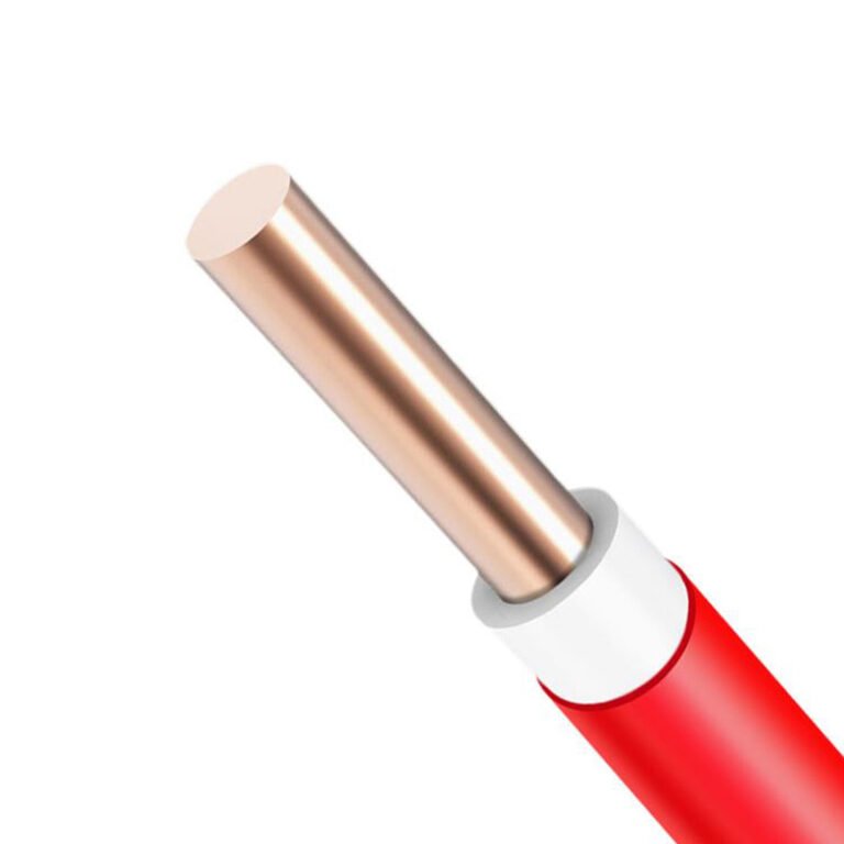
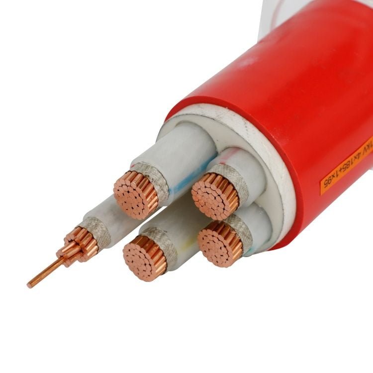
Specify the wrong cable type on a purchase order — or let a site electrician substitute “something similar” from the storeroom — and the consequences stack up fast. Insulation that can’t handle the installation environment degrades in months instead of decades. Conductors undersized for actual current density run hot, trip protection relays, and in the worst cases become a fire risk. Rerunning cable through a conduit system or a cable tray buried under a production line is not a half-day job; it routinely means days of downtime and rework costs that dwarf whatever was saved on the original spec.
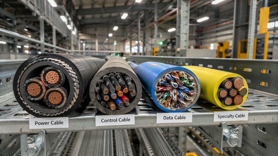
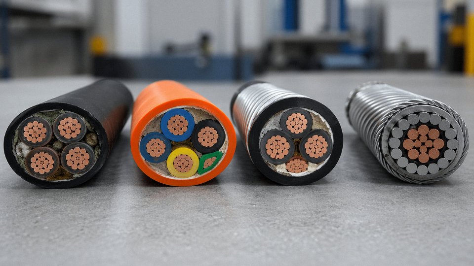
The four main types of cable are: power cable (for transmitting electrical energy at low, medium, or high voltage), control cable (for instrumentation and switching circuits), communication and data cable (for signal transmission including structured cabling and fiber optic), and specialty cable (covers flexible, fire-resistant, armored, and application-specific designs). Each type is engineered around a distinct combination of conductor class, insulation system, and mechanical construction.
What makes this genuinely complicated in practice is that those four categories don’t sit in neat boxes. A single installation — say, a process plant or a large commercial building — will use cables from all four groups, often running in parallel trays, and the selection criteria for each overlap in ways that trip up even experienced procurement teams. The global cable market is on track to exceed USD 225 billion by 2028, growing at roughly 5.5% annually, which means the range of products, standards, and suppliers a buyer has to navigate is only getting wider. Understanding where each cable type starts and stops is the only reliable way to write specifications that hold up.
Power Cables: Construction, Voltage Classes, and Core Industrial Applications
Power cables are the workhorses of any electrical infrastructure — designed specifically to transmit and distribute electrical energy rather than carry signals or data. They run from the transformer yard to the switchroom, from the substation to the wind turbine base, from the mine surface to the face conveyor. Volume-wise, they represent the largest single segment of global cable demand, and the market reflects that: with the overall cable industry projected to exceed USD 225 billion by 2028 at a CAGR of roughly 5–6%, power cable drives a disproportionate share of that growth, particularly in grid modernization and renewable energy buildout.
Voltage Classes — Why the Distinctions Actually Matter
The industry divides power cables into four voltage tiers: low voltage (LV, up to 1 kV), medium voltage (MV, 1–35 kV), high voltage (HV, 35–220 kV), and extra-high voltage (EHV, above 220 kV). These aren’t arbitrary marketing labels. Each tier demands fundamentally different insulation geometry, screen design, and jointing methodology. A plant electrician pulling in LV feeder cable can do it with basic tools and in-house crew; a 110 kV termination on an HV cable requires factory-trained jointers, controlled humidity, and often a third-party witness test. Get that boundary wrong during project planning and you’ll be scrambling for specialist contractors mid-schedule.
Conductor: Copper vs. Aluminum
Copper’s conductivity runs around 58 MS/m; aluminum sits at roughly 35 MS/m. That gap means an aluminum conductor needs a cross-section approximately 1.6 times larger to carry the same current. In practice, current densities for copper conductors typically fall between 1 and 6 A/mm², while aluminum runs 0.8–4 A/mm², with the actual figure depending heavily on insulation class, installation method, and ambient temperature.
Despite the conductivity disadvantage, aluminum wins decisively for large cross-section underground runs and overhead lines — it’s roughly 70% lighter than copper at equivalent cross-section, which matters enormously for cable tray loading, trench backfill consolidation, and overhead sag calculations. For industrial plant feeders below 50 mm², copper usually makes more sense: the joints are simpler, the terminations are more forgiving, and theft risk is a real operational concern in some regions that makes aluminum’s lower scrap value an accidental advantage.
Insulation Systems
XLPE (cross-linked polyethylene) has largely displaced PVC in modern medium- and high-voltage construction. The thermal ceiling tells you why: XLPE handles 90°C continuous conductor temperature and survives 250°C short-circuit events, versus PVC’s 70°C continuous limit. That 20°C difference in steady-state rating translates directly to ampacity — sometimes 10–15% more current-carrying capacity from the same physical cable. PVC still shows up in LV building wire and control cable where cost sensitivity is high and temperatures are moderate. EPR (ethylene propylene rubber) has a niche in genuinely cold environments and shipboard or mining applications where flexibility at low temperatures matters more than thermal efficiency.
Armoring Options
Steel wire armoring (SWA) is the standard for direct burial — it resists mechanical damage during backfill compaction and gives reasonable rodent resistance. For single-core cables, though, SWA creates a problem: the steel forms a closed magnetic loop around each conductor, generating hysteresis losses that can reduce efficiency meaningfully on loaded circuits. Aluminum wire armoring (AWA) breaks that loop while still providing mechanical protection, which is why single-core MV cables almost always specify AWA. In rodent-heavy environments — agricultural sites, certain tropical installations — double steel tape armoring adds a tighter mechanical barrier, though it adds weight and stiffness you’ll notice when pulling around bends.
Standards You’ll Actually Reference
IEC 60502 covers the 1 kV–30 kV range and is the backbone of most international procurement specs. IEC 60840 picks up from 30 kV to 150 kV; IEC 62067 governs above 150 kV. BS 5467 remains common in UK-influenced markets. For conductor construction specifically, IEC 60228 classifies stranding from Class 1 (solid) through Class 6 (extra-flexible), and ASTM B8 covers stranded copper conductors for North American projects.
XLPE-insulated power cables rated to IEC 60502 can sustain a conductor temperature of 90°C continuously and withstand 250°C under short-circuit conditions.True
These limits are specified in IEC 60502-1 and IEC 60364 derating tables, and are consistent with XLPE material performance data from major insulation compound suppliers. Conductor temperature limits directly determine ampacity in IEC 60287 calculations.
Application Matrix and Jinda’s Power Cable Range
Underground urban distribution networks, wind farm collection grids, solar farm AC string cabling, industrial plant feeders, shipboard power, mine circuits — power cables appear in virtually every sector. The specific construction varies considerably between them. A wind farm collection cable needs excellent wet-aging resistance and often deals with dynamic thermal cycling; a mine power cable may need additional flame-retardant and anti-static properties on top of armoring.
Jinda’s power cable range includes the YJV, YJLV, YJV22, and YJLV22 series (XLPE-insulated, with and without steel wire armoring, copper and aluminum conductor variants) from 0.6/1 kV through 26/35 kV, with conductor cross-sections spanning 1.5 mm² to 1,000 mm². That range covers most industrial and distribution applications without needing a custom construction.
Selection Checklist — Don’t Shortcut This
Ampacity calculation per IEC 60287 comes first — burial depth, soil thermal resistivity, grouping factor, and ambient temperature all feed into it, and assuming “standard conditions” on a dense cable trench or poorly backfilled direct-burial run will leave you undersized. Voltage drop needs checking independently, especially on long LV runs to remote loads. Short-circuit withstand (conductor cross-section must survive the prospective fault current for the clearing time of the upstream protection) is easy to overlook at specification stage and painful to discover during commissioning. Installation method — trefoil versus flat formation — affects both ampacity and the inductive reactance of the circuit. Finally, ambient temperature derating: a cable rated at 90°C in 25°C ground is a different cable in 40°C ground, and that 15°C difference can knock 8–12% off your allowable current depending on the installation configuration.
Control Cables: Signal Routing, Multi-Core Configurations, and Shielding Requirements
Control cables do one job power cables don’t: they carry intent, not energy. The signal telling a pump to start, the feedback loop confirming a valve position, the 4–20 mA trace from a pressure transmitter back to the DCS — all of that rides on control cable. Voltage ratings are modest, usually 450/750 V or 0.6/1 kV, and current levels are low enough that thermal capacity is almost never the design constraint. What matters here is signal integrity, mechanical flexibility, and noise immunity.
Core Count, Conductor Sizing, and Stranding
Multi-core configurations are where control cables earn their complexity. Practical assemblies run from 2 cores up to 61 cores in a single jacket, and conductor cross-sections typically fall between 0.5 mm² and 10 mm², with 0.75 mm² and 1.5 mm² being the most common sizes in process plant instrumentation loops. Larger cross-sections — 4 mm² or 6 mm² — appear in motor starter and protection circuits where relay coil currents are heavier.
Stranding class matters a lot in moving applications. A cabinet door that opens and closes 50 times a day, a robotic arm cable track, a drag chain on a gantry crane — these all demand Class 5 or Class 6 fine stranding per IEC 60228. Solid or coarse-stranded conductors will work-harden and fracture at the flex point within months. In static panel wiring, Class 2 stranded is usually fine and costs less, so there’s no reason to over-specify.
Insulation and Jacket Materials
PVC insulation covers the majority of general industrial installations. It’s cost-effective, easy to terminate, and well-suited to the 60–70 °C ambient conditions typical of a motor control center or a field junction box. But PVC burns and produces hydrogen chloride gas, which is corrosive to electronics and toxic to people in confined spaces.
That’s why LSZH (low-smoke zero-halogen) compounds are mandatory on offshore platforms, in rail tunnels, and in public buildings — anywhere that an evacuation route might fill with smoke. The material cost premium over PVC runs roughly 25–50% depending on cable diameter and compound grade, but in a fire event on an FPSO or in a metro station, the reduced fume toxicity is not negotiable.
Silicone rubber insulation handles the other extreme: furnace control wiring, kiln instrumentation, and similar environments where ambient temperatures can reach 180 °C or higher. Silicone cables are softer, more expensive, and require careful handling during installation because the jacket tears more easily than PVC. Worth the trouble in a ceramics plant or a heat treatment line. Overkill in a standard MCC room.
Shielding Configurations and EMI
This is where most specification errors happen. Variable frequency drives, large motor contactors, and switching power supplies all generate high-frequency electromagnetic interference that couples directly into unshielded signal conductors running in the same cable tray.
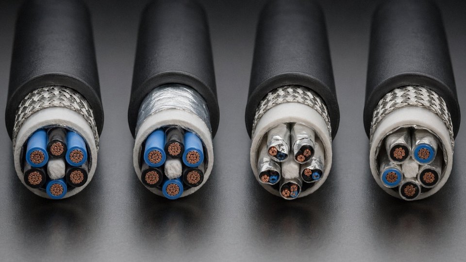
An overall foil-and-drain shield around the entire cable bundle provides a basic level of protection and is adequate when all cores carry signals of similar type and the interference source is distant. Individual pair or triad shielding — where each signal pair gets its own foil screen — is required when the cable carries both analog 4–20 mA loops and digital pulse signals in the same jacket, or when the cable runs close to VFD output conductors. Without individual screening, the 10 kHz switching noise from an adjacent drive can appear as a false analog reading or trigger spurious relay operations.
At substation commissioning, a recurring problem involves installers substituting an unscreened power cable for a specified screened control cable to get the job done before inspection — usually because the screened type wasn’t in the site store. The result shows up two weeks later as intermittent protection relay trips that take days to trace. The cable is the last thing anyone checks.
Using an unscreened power cable in place of a specified screened control cable can cause EMI-induced relay malfunctions and false trips in protection systems.True
Unscreened conductors in high-interference environments pick up switching noise from VFDs and contactors. This noise appears on signal lines and can exceed the threshold voltage for relay operation or corrupt 4–20 mA analog signals, causing control system faults that are notoriously difficult to diagnose.
Color Coding, Core Identification, and Traceability
IEC 60446 sets color conventions for low-voltage wiring, and for high core-count assemblies — anything above roughly 5 or 6 cores — sequential number printing on the insulation becomes the practical identification method. A 37-core cable with numbered cores can be terminated systematically against a drawing; a 37-core cable with repeating colors cannot.
For large export projects, Jinda prints core numbers at regular intervals along the insulation length, not just at the ends, which matters when a long run gets cut in the field and the installer needs to identify cores mid-cable without pulling back to a terminal box.
Standards and Applications
The primary standards governing control cables are IEC 60227 and IEC 60245 (PVC and rubber insulated respectively), the VDE 0281 series for German-market specifications, and BS EN 50525 for the broader European market. DCS and SCADA wiring in refineries and power stations, BMS networks in commercial high-rises, motor protection circuits in manufacturing plants, and fire detection loops in public infrastructure all rely on correctly specified control cable. Getting the shielding and insulation type right at the procurement stage costs almost nothing. Getting it wrong costs days of fault-finding and, in some cases, a protection system that doesn’t operate when it needs to.
Instrumentation Cables: Precision Signal Integrity in Hazardous and Process Environments
Instrumentation cables occupy a different world from power or control cables. The signals they carry — 4–20 mA analog loops, millivolt-level thermocouple outputs, RTD circuits, HART, Foundation Fieldbus, Profibus DP — are small enough that a few millivolts of noise or a capacitance mismatch can corrupt a reading and send a process controller chasing a ghost. In an oil refinery or an LNG terminal, that’s not an inconvenience. It’s a potential trip event, a bad batch, or worse.
What Actually Separates Instrumentation Cable from Control Cable
The physical difference is subtle enough that procurement teams sometimes conflate the two, and that mistake shows up during commissioning. Control cables route on/off commands and status signals at relatively forgiving voltage levels. Instrumentation cable carries precision analog and low-energy digital signals where the electrical parameters of the cable itself matter — not just the insulation voltage rating.
Tighter impedance control is one marker. Individual pair or triad shielding with a dedicated drain wire is another. Capacitance typically runs 80–120 pF/m depending on conductor spacing, insulation material, and screen design; push past the upper end of that range on a long thermocouple run and you start seeing sluggish response in fast-scanning DCS channels. Most demanding process plant specs call for individually screened plus overall screened (IS + OS) construction, where each pair has its own foil and drain, and the whole cable gets a second overall screen. That kills crosstalk between pairs and blocks common-mode interference from nearby power cables running in the same tray — which, in a real plant, they always do.
Conductors are typically 0.5–2.5 mm² tinned copper, twisted to cancel inductive noise pickup. The tin plating isn’t just a specification checkbox; in humid offshore environments or chemical plants with aggressive vapors, bare copper corrodes at terminations over months, and a corroded thermocouple junction block is a troubleshooting nightmare.
Intrinsic Safety Wiring and Hazardous Area Requirements
Zone 1 and Zone 2 installations under IEC 60079-14 impose strict limits on the cable’s stored energy — maximum capacitance and inductance values that must stay within the entity parameters certified for the IS barrier or Zener diode barrier at the field junction box. Exceed those limits, even slightly, and the IS system’s certification becomes void. Blue outer sheath and blue core identification are the standard visual marker for IS circuits, and mixing blue-sheathed instrumentation cable with standard grey cable in the same tray labels is the sort of shortcut that creates real installation hazards during maintenance.
ISA-RP 12.6 and API RP 552 add application-layer guidance on top of the IEC framework — particularly relevant for US Gulf Coast projects and offshore platforms that blend both regulatory environments.
Thermocouple Extension vs. Compensating Cable
This is a distinction worth spelling out clearly because it’s frequently misunderstood, even by experienced engineers who haven’t worked directly with temperature measurement loops.
Extension cable uses the same thermoelectric alloy as the thermocouple itself — a Type K extension cable, for instance, uses Chromel and Alumel conductors. It maintains accurate EMF transmission across a wide temperature range but is significantly more expensive. Compensating cable uses a different, cheaper alloy that approximates the thermocouple’s EMF characteristics only within a limited temperature window, usually 0–200 °C at the cable itself. Use a compensating cable in a hot cable tray near a furnace wall and you introduce a measurable temperature error that traces back to nothing obvious on the loop drawing.
IEC 60584 covers Types J, K, T, E, N, R, and S, specifying both the alloy pairs and the tolerance classes. Type K dominates general process plant work; Type R and S appear in high-temperature applications like glass furnaces and kilns. Getting the extension vs. compensating choice wrong is one of those slow errors — the reading drifts, calibration can’t fix it, and the root cause takes days to find.
Instrumentation cables used in Zone 1 hazardous areas must comply with IEC 60079-14 capacitance and inductance limits to maintain intrinsic safety certification.True
IEC 60079-14 specifies that the total cable capacitance and inductance in an IS circuit must not exceed the entity parameters of the associated IS barrier; exceeding these values invalidates the IS certification and creates a potential ignition risk in explosive atmospheres.
Armor, Jacket, and Harsh Environment Construction
Offshore platform and chemical plant installations typically specify 304 stainless steel wire braid armor rather than galvanized steel wire armor — salt air and acidic process vapors attack zinc-coated steel faster than most maintenance cycles catch. Polyamide (nylon) overjackets add abrasion resistance for tray installations where cables shift during thermal cycling or maintenance traffic. For fire-survival requirements, IEC 60332-3 flame-retardant ratings are standard on most process plant specs.
Pharmaceutical cleanrooms and food processing plants bring different constraints: smooth, cleanable jacket surfaces, resistance to cleaning chemicals, and in some cases FDA-compliant materials — the armor and jacket spec shifts entirely even though the core electrical construction stays similar.
Communication and Data Cables: From Structured Cabling to High-Speed Fiber Networks
Communication cables are the nervous system of any modern facility, and they get underspecified more often than any other cable type. A power cable failure is visible — breakers trip, motors stop. A marginal data cable fails slowly: packet retries climb, latency spikes, fieldbus nodes drop off intermittently, and the maintenance team spends weeks chasing a “software problem” that’s actually a Cat 5e run pushed 15 meters past its rated distance in a cabinet full of VFD noise.
There are three distinct sub-families here, and they are not interchangeable.
Twisted-Pair Copper Data Cables (Cat 5e Through Cat 8)
The Category rating system is straightforward in principle and routinely abused in practice. Cat 5e handles 100 MHz and 1 Gbps adequately for office and light industrial work. Cat 6 doubles the bandwidth to 250 MHz, supporting 10 Gbps over short runs (roughly 37–55 m, depending on ambient interference). Cat 6A extends that to 500 MHz and holds 10 Gbps out to the full 100 m channel. Cat 7 at 600 MHz and Cat 8 at 2,000 MHz push into 25–40 Gbps territory — Cat 8 is genuinely a data center spine cable, not something you’d pull through a factory tray for general use.
The shielded versus unshielded decision matters most in industrial environments. UTP (unshielded twisted pair) is fine in clean office infrastructure. Put it near a 690 V VFD, a welding cell, or an MCC room and you’re asking for trouble. STP, FTP, and SFTP constructions add foil and/or braid shields at the pair or overall level, but — and this is worth stating plainly — a shielded cable with a poorly terminated or floating shield is sometimes worse than UTP because the shield becomes an antenna. Proper grounding at one end (typically the patch panel end) is non-negotiable.
Cat 6A STP cable can maintain 10 Gbps throughput at 100 m even in moderate EMI environments when the shield is correctly terminated to a grounded patch panelTrue
This aligns with TIA-568-C.2 and ISO/IEC 11801 channel performance requirements for Class EA cabling, provided installation practices — bend radius, connector termination quality, and shield continuity — are followed correctly.
Coaxial Cables: 50-Ohm vs. 75-Ohm
Coaxial construction — center conductor, dielectric, braided or foil shield, outer jacket — gives coax its low-loss, high-rejection characteristics that twisted pair can’t match at RF frequencies. The impedance split is application-driven. Fifty-ohm coax (the RG-58, RG-213, LMR series) is the standard for RF transmission, antenna feeds, and industrial Ethernet in older SCADA topologies. Seventy-five-ohm (RG-6, RG-11, and equivalent types) is the broadcast and CATV world — if you’re pulling cable for video surveillance infrastructure or a facility television distribution system, 75-ohm is the correct choice. Mixing the two in a system causes impedance mismatch, reflected power, and signal loss that no amplifier will cleanly fix.
Attenuation in coax increases with frequency and distance. An RG-6 run of 100 m at 1 GHz typically sees 15–25 dB loss depending on cable quality and connector workmanship — that’s why long CATV runs use line amplifiers or fiber backbone with coax only at the final drop.
Fiber Optic Cables: Single-Mode and Multimode
Fiber is where communication cable specification gets genuinely consequential in modern infrastructure. Single-mode fiber (OS1/OS2, 9/125 µm core/cladding) transmits at 1,310 nm or 1,550 nm wavelengths and supports distances up to roughly 10 km on OS1 (tight-buffered, indoor/outdoor) and 80 km or beyond on OS2 with appropriate transceivers. This is the cable for campus backbone runs, 5G fronthaul and backhaul links, and any inter-building connection where distance rules out copper entirely.
Multimode fiber (OM1 through OM5, either 62.5/125 µm or 50/125 µm) is the practical choice for data center horizontal runs and campus links up to roughly 400 m on OM3/OM4 at 10 Gbps, or up to 2 km on lower data rates. OM5 wideband multimode extends usefulness by supporting shortwave wavelength division multiplexing — useful if you’re building out a data center and want the cabling infrastructure to support 100 Gbps and beyond without a full re-pull.
Jacket material matters in enclosed spaces. LSZH (low-smoke zero-halogen) jackets are not a marketing specification — in a data center, hospital corridor, or any poorly ventilated riser, a PVC jacket fire produces hydrogen chloride gas that damages equipment and is acutely toxic to occupants. Most serious data center projects now specify LSZH as baseline, and several national codes require it.
Industrial Fieldbus and Protocol-Specific Communication Cables
This is the category that causes the most expensive mistakes. PROFIBUS DP requires a specific 150-ohm characteristic impedance, defined capacitance, and a violet outer jacket per IEC 61158. PROFINET, EtherNet/IP, and DeviceNet each have published cable specifications tied to their protocol performance requirements. A procurement manager who substitutes standard Cat 6 for PROFIBUS cable because “it’s just Ethernet” will eventually deal with intermittent node dropouts, particularly at segment lengths above 50–60 m or in electrically noisy environments. The cable specs exist because the protocol timing and signal integrity depend on them.
Standards governing this family include ISO/IEC 11801 and TIA-568 for structured cabling, IEC 60793 and IEC 60794 for fiber optic cable construction and test methods. Cross-referencing the installation standard with the protocol vendor’s cable specification before procurement is basic due diligence, but it’s skipped often enough that it’s worth stating.
One operational principle that applies across all three sub-families: design for the next generation standard, not the current one. The cost difference between Cat 6A and Cat 6 conduit fill is minor at installation. Pulling new cable through a finished ceiling or a congested cable tray five years later is not minor. Facilities that installed Cat 5e in 2015 to save a few cents per meter are re-cabling now. The same logic applies to fiber: installing OS2 single-mode where multimode would technically suffice today costs little extra and eliminates future upgrade constraints entirely.
Side-by-Side Comparison: How to Match Cable Type to Voltage, Environment, and Signal Type
The four cable types are not interchangeable, and the consequences of getting this wrong range from nuisance interference to catastrophic failure. A quick comparison table is where most engineers start — but the table only works if you understand what each column is actually telling you.
Master Comparison Table
| Parameter | Power Cable | Control Cable | Instrumentation Cable | Communication / Data Cable |
|---|---|---|---|---|
| Voltage rating | LV (≤1 kV) to EHV (≥220 kV) | Typically 300/500 V to 0.6/1 kV | 150 V to 300/500 V (signal level) | ≤100 V (copper); optical (fiber) |
| Conductor size range | 1.5 mm² to 2,500 mm² (IEC 60228 Class 1–2) | 0.75 mm² to 10 mm² (Class 2–5) | 0.5 mm² to 2.5 mm² (Class 2, sometimes 5) | 22–26 AWG copper; 9/125 µm or 50/125 µm fiber |
| Insulation type | XLPE, EPR, PVC (HV: XLPE standard) | PVC, LSZH, XLPE | XLPE, LSZH, FEP (high-temp) | PE, LSZH, fluoropolymer (data); silica glass (fiber) |
| Shielding | Optional (MV/HV: metallic screen standard) | Overall braid or foil, sometimes none | Individual pair/triad screens + overall screen | UTP, FTP, STP; coaxial; fiber is immune |
| Armoring | SWA, STA, wire braid (buried/mechanical risk) | Light SWA or unarmored (tray routed) | Usually unarmored; SWA if mechanically exposed | Rarely armored copper; armored ADSS/OPGW for fiber |
| Typical core count | 1–5 cores | 4–48 cores | 2 (pairs) to 20+ pairs/triads | 1–144 fiber; 1–4 pair copper (Cat/industrial) |
| Primary function | Energy delivery | Relay, switch, actuator switching | Analog/digital process signals (4–20 mA, thermocouple, RTD) | Ethernet, fieldbus, PROFINET, SCADA comms |
| Key standards | IEC 60502, IEC 60840, IEEE 1202 | IEC 60227, IEC 60332 | IEC 60332, ISA-RP12.06, ANSI/ISA 50.1 | TIA-568, IEC 61156, IEC 60793 |
Decision Tree: Work Through Function First, Then Environment
Start with what the cable has to do, not what it looks like in the catalog.
If it carries load current to a motor, transformer, or busbar — it’s a power cable. Full stop. Then ask: what voltage class, and is it buried, trayed, or directly embedded in concrete? Burial with mechanical risk drives you to SWA or STA; high-temp environments push insulation choice from PVC toward XLPE or EPR.
If it switches a relay coil, drives a solenoid valve, or routes discrete on/off signals between a PLC and a marshalling panel, that’s a control cable. Voltage is low, conductor cross-section is modest, but core count can be high. In hazardous areas, you need to check whether the cable construction meets the zone classification — IEC 60079 requirements apply regardless of cable type.
Process signals — 4–20 mA loops, thermocouple extensions, RTD wiring — belong on instrumentation cable. Individual pair screening is not optional here. Running an unscreened two-core cable in a DCS loop through a cable tray shared with 415 V motor feeders will inject noise that looks exactly like a real process upset. I’ve seen this cause false shutdowns on a compressor skid where the maintenance team spent three days chasing an instrument fault that was pure EMI.
Data and communications cables are the final branch. In a VFD-dense plant, general-purpose Cat 6 will not survive the common-mode noise environment without shielding. Industrial PROFINET cables — rated for EMC per IEC 61784 — are built differently than office-grade structured cabling. The jacket, the drain wire termination, the connector compatibility: all of it matters.
Common Mis-Specification Pitfalls
Using SWA power cable in place of screened instrumentation cable in a DCS loop is one of the most frequent errors on fast-track EPC projects. The armoring offers mechanical protection but zero EMI screening — and the larger conductor cross-section adds unnecessary cost.
Substituting PVC-insulated cable in a zone that specifies LSZH is a compliance issue that will surface during third-party audit or insurance review, not during commissioning. Fix it before cable installation begins; pulling and replacing tray-routed cables after the fact costs multiples of the original material saving.
XLPE insulation typically extends cable service life by 20–40% compared to standard PVC under equivalent thermal loading conditions.True
XLPE (cross-linked polyethylene) has a rated conductor temperature of 90°C continuous versus 70°C for PVC under IEC 60502, and its superior resistance to thermal aging, moisture, and mechanical stress translates directly to longer in-service life under equivalent operating conditions — a range of 20–40% improvement is consistent with published IEC and field service data.
The ROI on specifying XLPE over PVC in medium-voltage feeders feeding critical loads is clear: lower derating penalty means you may be able to reduce conductor cross-section one step, partially offsetting the premium. LSZH compounds in tunnel, marine, or public building installations reduce toxic gas evolution in fire — the cost delta over PVC is typically 15–35% on jacket material alone, which is small relative to the liability exposure from a non-compliant installation.
Segregation in Cable Trays
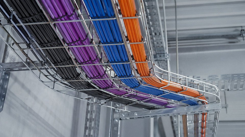
Running all four cable types in a single tray is a real-world reality, especially in retrofit projects where tray space is fixed. IEC 61537 and IEEE 1185 both require physical separation between power and signal cables — typically a minimum of 150–300 mm horizontal separation, or a grounded metallic divider, depending on voltage level and tray width. In practice, many plants run power in the bottom tier and instrumentation/data on upper tiers with a solid metal divider. This is not just a code requirement; it directly affects signal quality and insulation longevity through both EMI coupling and thermal loading.
How Jinda Supports BOM Optimization
On large EPC projects, cable schedule errors accumulate quietly and surface as expensive change orders during procurement closeout. Jinda’s technical support team works with procurement managers and EPC engineers early in the BOM preparation phase — reviewing cable schedules against installation design parameters, flagging mismatches in insulation class or screening requirements, and consolidating SKUs to reduce procurement complexity. For projects spanning multiple voltage systems, installation environments, and communication protocols, that kind of structured review usually turns up specification inconsistencies that would otherwise result in rework.
Key International Standards and Certification Requirements by Cable Type
Standards are where procurement goes wrong more often than most engineers admit. A cable that meets IEC but not the local national standard, or that carries CE marking but lacks the CPR fire classification your building contractor requires — that’s a rejected shipment, a project delay, or worse, a failed inspection on a live site. Getting this right before you write the purchase order is worth the hour it takes.
The Three-Tier Standards Landscape
Think of cable standards as a layered system. At the top sit the international bodies — IEC and ISO — whose documents form the technical baseline that most regional and national standards either adopt, modify, or reference. IEC standards are the common language between a cable factory in Shandong and a project engineer in Rotterdam or Riyadh.
The middle tier is regional. Europe’s EN standards (published through CENELEC) are usually direct adoptions of IEC documents, sometimes with tighter tolerances or additional fire performance requirements. BS EN prefixes indicate a British adoption of a European standard — still relevant post-Brexit for UK projects. VDE standards (Germany) and NF standards (France) operate similarly, though VDE has historically maintained stricter requirements on some conductor flexibility classes. AS/NZS standards for Australia and New Zealand follow the IEC framework but include local environmental considerations like UV resistance for outdoor runs in high-UV climates.
National standards form the third tier. China’s GB/T series is largely harmonized with IEC but not identical — insulation wall thicknesses and test voltages occasionally differ, which matters when a cable made to GB/T gets submitted against an IEC spec. In North America, NEC (the installation code) works alongside UL product standards; a cable can be UL-listed but still fail a NEC installation requirement if it’s installed incorrectly. GOST standards, used across Russia and much of the CIS, remain significantly divergent from IEC, which creates real friction on projects that cross those borders.
Power Cable Standards Quick Reference
IEC 60502-1 covers extruded solid dielectric insulated power cables from 1 kV up to 30 kV; Part 2 extends this to 150 kV. For high-voltage transmission cables, IEC 60840 picks up from 30 kV to 150 kV and IEC 62067 covers above 150 kV — these are where type testing requirements become genuinely demanding, involving long-duration voltage tests and thermal cycling. In North America, UL 1072 governs medium-voltage power cables and CSA C22.2 No. 2 covers the Canadian market. AS/NZS 1429 Parts 1 and 2 address the Australian and New Zealand LV and MV range.
One practical point: IEC 60502 type tests and routine tests are different obligations. Type tests are done on cable designs, not every drum. A supplier showing a type test certificate from five years ago on a slightly different conductor cross-section is not the same as a product that was tested as-built. Ask for the test report, not just the certificate number.
Control Cable Standards
IEC 60227-3 and -5 cover PVC-insulated flexible control cables for fixed and flexible installation respectively. IEC 60245-4 addresses rubber-insulated versions, still common in mobile equipment and mining. BS EN 50525-2-31 is the European harmonized document most European OEM and panel builders reference. VDE 0281 remains the German national counterpart and is sometimes specified by German machine builders even on export equipment — worth checking in the machine documentation before you specify a local substitute.
Instrumentation Cable Standards
Flame propagation testing is the critical performance axis for instrumentation cables in process plants. IEC 60332-1 tests a single vertical cable; passing it is a baseline, not a guarantee for a cable tray full of cables. IEC 60332-3 tests bunched cables in a tray — Categories A, B, C, and D vary the volume of non-metallic material burned, with Category A being the most severe. Most oil and gas project specs require at least Category C for instrumentation cable bundles.
IEC 60079-14 governs electrical installation in hazardous areas and dictates cable construction, shielding, and maximum capacitance and inductance parameters for intrinsically safe (IS) circuits. This is not optional in Zone 1 or Zone 2 classified areas — a cable that isn’t compliant with 60079-14 can invalidate the IS loop certification entirely, which carries serious consequences during HAZOP review and insurance audits. ICEA S-82-552 is the North American instrumentation cable standard; BS 5308 Parts 1 and 2 cover individual and collective screened types and remain widely referenced in Middle East and African projects with British heritage specifications.
Communication Cable Standards
ISO/IEC 11801 Edition 3 defines the structured cabling framework for commercial buildings; TIA-568.2-D is the North American equivalent and is slightly more prescriptive about component performance. For copper data cables, both documents define Category performance levels (Cat 6A being the current mainstream for new installations supporting 10GBASE-T). IEC 60793-2 classifies optical fiber types — single-mode, multimode OM1 through OM5 — and IEC 60794-1 sets the mechanical and environmental performance requirements for the cable assembly itself. IEEE 802.3 defines the physical layer for Ethernet, and it’s where you find the actual transmission requirements that a Cat 6A or OM4 cable needs to support — worth reading alongside the cabling standard rather than treating them as separate universes.
Fire Performance: Reading a Certificate Properly
Fire certificates are frequently misread. Each standard tests a specific behavior:
| Standard | What It Actually Tests |
|---|---|
| IEC 60332-1 | Single cable, vertical flame propagation |
| IEC 60332-3 (A/B/C/D) | Bunched cables in a tray, varying material volume |
| IEC 60331 | Circuit integrity — cable continues to function during fire |
| EN 50267 | Halogen acid gas emission from combustion gases |
| EN 50268 | Smoke density (light transmittance) |
A cable marketed as “fire resistant” without specifying which standard is essentially meaningless. IEC 60331 circuit integrity is a separate test from flame spread — a cable can pass 60332 and still fail 60331. For emergency systems (fire alarm, emergency lighting, evacuation comms), circuit integrity under IEC 60331 is usually the mandatory requirement, and it needs to be explicitly called out in your cable schedule.
A cable passing IEC 60332-1 flame propagation automatically meets IEC 60331 circuit integrity requirementsFalse
These are entirely separate tests. IEC 60332-1 measures whether a flame spreads along a single vertically mounted cable. IEC 60331 tests whether the cable continues to carry a circuit under fire conditions at a defined temperature (typically 750°C or 950°C) for a defined period. A cable can pass one and fail the other. Emergency circuit cables typically require both.
Third-Party Certification Bodies
For offshore and subsea applications, KEMA (now part of DNV) and DNV GL type approvals carry the most weight and are typically mandatory for oil and gas platform specifications. Marine cables must comply with classification society rules — Bureau Veritas (BV) and ABS are the two most common, though Lloyd’s Register and DNV have their own lists. UL listing is the practical entry requirement for the North American market; without it, getting a cable approved through a US or Canadian authority having jurisdiction (AHJ) becomes a project-specific headache.
CE marking in Europe covers the Low Voltage Directive (LVD) for cables up to 1 kV, but since 2017 the Construction Products Regulation (CPR) has added mandatory fire performance declarations for cables installed in buildings — the Euroclass system (Aca through Fca) runs parallel to IEC 60332/EN 50268 tests and must appear on the cable packaging and technical documentation for EU building projects. Many procurement managers conflate CE marking with CPR compliance; they’re related but not the same thing.
Jinda’s manufacturing and quality systems are certified to ISO 9001 and ISO 14001, with product approvals covering IEC, CE, and CPR classifications, as well as market-specific certifications for major export regions. When evaluating any supplier — Jinda included — ask for the specific certificate number, the certifying body, the scope of the certification (which product types and cross-sections are covered), and the expiry date. A credible manufacturer should be able to produce this documentation without hesitation.
Installation Best Practices That Extend Cable Service Life Across All Four Types
Getting the cable selection right is only half the job. A correctly specified MV XLPE cable that gets kinked during pulling, or a screened instrumentation cable run in the same tray as a 6.6 kV feeder, will fail early — sometimes catastrophically. The installation phase is where most service-life problems actually originate, and in my experience, the root cause is almost always either skipped calculations or compressed site schedules that push crews past safe limits.
Minimum Bending Radius — the Number Most Often Ignored
Every cable type has a minimum bending radius, and they are not interchangeable. Power cables typically require 12–20× the overall diameter during installation; the exact multiplier depends on voltage class, armoring type, and whether the cable is single-core or multicore. Instrumentation cables are more forgiving at 6–10× OD, but fiber optic cables demand the most discipline: 10–20× OD during the pull itself, widening to 15–30× OD in the final installed position. Violating these limits does not always produce an immediate fault. Insulation cracks and fiber micro-bending losses develop gradually, and the cable passes commissioning testing only to fail six months into service under thermal cycling. Pulling around a structural steel corner with a timber block instead of a proper cable roller set is one of the most common field shortcuts — and one of the most damaging.
Tray Segregation Under IEC 61537
IEC 61537 is unambiguous: power cables and signal or instrumentation cables must be physically separated. In practice, that means a minimum air gap of roughly 150–300 mm, or a solid metallic divider in the tray. The actual gap required depends on the voltage class of the power circuit and the sensitivity of the signal circuit. Fiber optic cables should never share a tray with high-voltage power cables — not because of electromagnetic interference (fiber is immune to that) but because of the mechanical and thermal risk during a fault event. A burning MV cable in the same tray will destroy a fiber backbone.
Pulling Tension Limits
Calculate maximum pulling tension before the pull, not after something goes wrong. The ICEA T-34-664 formula for copper conductors — 0.008 × cross-section (mm²) × number of conductors, giving a result in kgf — is straightforward and takes maybe five minutes. Exceeding the limit elongates conductors, damages insulation at the conductor surface, and can shear compression joints. Lubricant selection matters too; use a cable-specific compound, not general grease, and check compatibility with the outer sheath material.
Termination and Jointing Quality
At medium voltage, stress control geometry at terminations is not optional. Semi-conducting tape must be cut cleanly and removed completely from the XLPE insulation surface — even a small residue of semi-con material left on the insulation will initiate partial discharge, and partial discharge in XLPE is a slow but terminal failure mode. Compression lug selection per IEC 61238-1 matters: the lug must match the conductor class (Class 2 stranded versus Class 5 flexible, for instance) and the barrel bore must be correct for the actual conductor diameter, not the nominal cross-section.
Partial discharge in XLPE cable terminations is a primary cause of MV cable failures within the first two years of service when semi-con tape removal is incomplete.True
Industry testing and utility failure analysis consistently identify contaminated termination interfaces as a leading source of early partial discharge activity in XLPE-insulated medium voltage cables. Proper preparation per manufacturer instructions and IEC 60840 guidance is a recognized preventive measure.
Sealing, Glands, and Direct-Burial Joints
Direct-burial joints need IP68 as a minimum — not IP67, which is only rated for temporary immersion. Submarine cable should arrive from the factory with a lead or aluminum sheath already fitted; field-applied sheath repairs on submarine routes are a maintenance liability. Cable glands are frequently misspecified: SWA (steel wire armored) cables need glands designed for round wire armor, while STA (steel tape armored) cables need a different clamping geometry. Getting this wrong compromises both the IP rating and the armor’s fault current carrying path.
Thermal Backfill for Direct-Buried Power Cables
Standard native soil has thermal resistivity that varies widely — easily 2.5–3.5 K·m/W in dry sandy conditions, which throttles ampacity. Engineered thermal backfill compounds typically achieve 0.9–1.2 K·m/W and can increase cable ampacity by roughly 10–20% compared to leaving native soil in place. On large projects, that ampacity gain can justify a smaller conductor cross-section, which affects procurement cost significantly. The calculation should be done at the design stage, not as an afterthought.
Commissioning Tests — Do Not Skip the Boring Ones
Insulation resistance testing with a Megger (500 V DC for LV circuits, 5 kV DC for MV) catches moisture ingress and damaged insulation before energization. Cables above 3.3 kV should receive partial discharge testing at commissioning; a factory-tested cable that has been poorly installed can show elevated PD activity immediately. Fiber optic links need OTDR testing to verify splice losses and confirm no micro-bending exists. Instrumentation and control loops need loop resistance checks — a corroded crimp or a misrouted core is far easier to fix before the panel is live.
Documentation and Labeling
IEC 62491 and ISO 14617 provide labeling conventions that most engineering contractors adopt for tag numbering and routing identification. Drum number traceability matters for future maintenance: knowing which batch a cable segment came from allows targeted inspection if a quality issue surfaces years later. Jinda’s delivery documentation includes drum numbers, factory test reports, and conductor resistance data per IEC 60228 that integrate directly into as-built records, which is worth verifying with any cable supplier before committing to a large project supply package.
Frequently Asked Questions About the Four Types of Cable
What is the most important difference between a control cable and an instrumentation cable?
Purpose and signal sensitivity. Control cables carry switching commands, interlock signals, and relay outputs — typically at 24 V DC to 240 V AC — and the construction reflects that: multi-core, usually with an overall screen, but no particular obsession with capacitance or impedance. You’re switching things on and off, so a few picofarads of extra capacitance between cores is generally not a crisis.
Instrumentation cables are a different discipline entirely. They carry low-level analog signals — 4–20 mA loops, thermocouple millivolt outputs, RTD resistance values — where stray EMI coupling of even a few millivolts can corrupt a measurement. Each pair (or triad) is individually screened, capacitance is held to roughly 80–120 pF/m depending on the design, and in oil and gas or chemical plant applications the cable often needs to meet IEC 60079 requirements for use in intrinsically safe circuits. Using control cable in an instrumentation loop because it “looks similar” is one of the more common commissioning mistakes on new plant.
Can I use a power cable as a control cable in an emergency?
Technically, yes — the current will flow. In practice, an unshielded power cable run alongside other conductors in a busy cable tray will pick up significant EMI, and what comes out the other end may bear little resemblance to the intended control signal. For a temporary bypass of a mechanical limit switch during a maintenance window, probably fine. For permanent installation driving a PLC analog input or a protection relay, no. The high inter-conductor capacitance typical of power cable construction (often 300–600 pF/m on a multi-core) will cause signal attenuation and crosstalk that becomes progressively worse as run length increases.
What does LSZH mean, and which cable types require it?
LSZH — low-smoke zero-halogen — describes the outer jacket and bedding compound rather than the conductor or insulation system. In a fire, standard PVC jackets release hydrochloric acid gas and dense black smoke, both of which kill people and destroy electronics faster than the flames themselves. LSZH compounds char rather than burn freely, produce substantially less smoke, and don’t emit corrosive halogens.
It is typically mandatory for control, instrumentation, and data cables installed in confined public spaces — tunnels, airports, hospitals, offshore platforms, metro systems. Increasingly, project specifications for power cables in the same environments require it too, which does push cable cost up by roughly 15–30% versus a standard PVC jacket, depending on compound type and cross-section.
LSZH cables produce significantly less smoke and no halogen acid gases compared to standard PVC-jacketed cables in fire conditionsTrue
This is confirmed by IEC 60754-1/60754-2 (halogen content testing) and IEC 61034-2 (smoke density testing), which are the standard tests used to verify LSZH compliance in cable specifications worldwide.
How do I know if I need single-mode or multimode fiber?
Short runs inside a building or campus — up to about 300–550 m at 10–100 Gbps — suit multimode fiber well. OM3 and OM4 are the workhorses of data center horizontal and backbone runs; OM5 adds wideband support for wavelength multiplexing. The transceivers are cheaper and the installation tolerances are more forgiving because the larger core (50 µm) is easier to terminate in the field.
Single-mode (OS2, 9 µm core) is the right answer for anything longer, for all outside-plant runs between buildings or sites, and for any application where you want to keep options open for 400 Gbps or coherent transmission later. The fiber itself costs roughly the same as OM4, but single-mode transceivers run meaningfully more expensive — budget accordingly rather than discovering the mismatch after the fiber is in conduit.
What certifications should I ask for when buying cables for an offshore oil and gas project?
Start with the IEC 60092 series, which covers marine and offshore electrical installations. Fire performance should meet IEC 60332-3-22 (Category A) or -24 (Category B) for bunched cable tests, consistent with SOLAS requirements. Any cable entering a Zone 1 or Zone 2 hazardous area needs ATEX certification (for EU projects) or IECEx for international acceptance, with the relevant Ex component certificate covering the cable’s electrical parameters.
Third-party flag state or classification society approval matters enormously on offshore projects. DNV, Bureau Veritas, and ABS are the names you’ll see most often in project specifications; Lloyd’s Register and ClassNK appear on specific vessel types. Ask for the actual certificate documents, not just a supplier’s claim — and check expiry dates, because some manufacturers let approvals lapse quietly.
How does Jinda support overseas buyers who need project-specific documentation?
Jinda’s technical team handles cable schedule review, ampacity calculations against IEC 60287 or project-specific derating tables, and cross-reference sheets mapping IEC designations to ASTM, BS, or VDE equivalents — all in English. For projects requiring third-party inspection, Jinda coordinates factory witness testing and provides full material test reports (MTRs) covering conductor resistance, insulation resistance, voltage withstand, and jacket compound test results. This is not a sales brochure service; it’s genuinely useful for engineering teams who need to defend a cable specification to an EPC contractor or end-client.
What is the typical lead time for a large international cable order?
Standard sizes in common configurations — say, 4-core 16 mm² armored power cable or shielded 12-pair instrumentation cable in stocked compounds — can ship within 2–4 weeks from available inventory. The range widens considerably for custom work: unusual cross-sections, special insulation systems (mineral-insulated, fire-resistant ceramifiable compounds, specialized LSZH blends), or large project quantities in the 50–500 km range typically require 6–12 weeks of production lead time. That window depends heavily on conductor size, whether the project needs a specific copper or aluminum temper, and current mill loading. Get your cable schedule finalized and submitted early — on large projects, cable procurement is almost always on the critical path, and a four-week delay on the cable order has a way of becoming a six-week delay at the cable tray stage.
How Jinda’s Integrated Manufacturing System Supports Global Cable Procurement at Scale
Sourcing four cable types from four different suppliers is one of those procurement decisions that looks fine on a spreadsheet and causes real pain on site. Mismatched lead times, inconsistent conductor tolerances between vendors, and the administrative overhead of managing separate quality dossiers — these are problems Jinda’s manufacturing structure is specifically built to eliminate.
Five Production Bases, One Consolidated Order
Jinda operates five production bases across China with a combined floor area of roughly 470,000 m². In practice, what that scale means for a large EPC project is concurrent production: power cables, control cables, instrumentation cables, and communication cables can run on separate lines simultaneously rather than queuing behind each other. For a mixed-type order covering, say, a substations package plus a process plant instrumentation schedule, that parallel capacity typically shaves two to four weeks off the programme compared to splitting the order across specialist manufacturers — each of whom will sequence your job against their own backlog.
Vertical Integration Is Not a Marketing Line
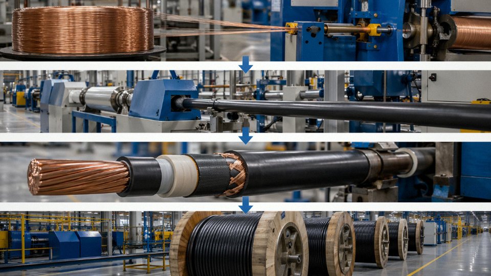
A lot of manufacturers call themselves “integrated” when they mean they buy finished components and assemble. Jinda’s integration starts at the rod breakdown stage: copper and aluminium conductor drawing, insulation and jacket extrusion, stranding and bunching, steel wire armoring, and final jacketing are all in-house processes. That matters because each hand-off between suppliers is a potential tolerance stack-up. When conductor geometry, insulation wall thickness, and armoring tension are all controlled under one quality system, you get tighter conformance to IEC 60228 dimensional requirements and — practically speaking — fewer drum rejections at goods-in. Lead times run roughly 20–30% shorter than comparable multi-vendor assembly routes, though the actual saving depends on order complexity and current line loading.
Testing and Traceability That Holds Up Under Project Scrutiny
Jinda conducts 100% spark testing on all insulated cores and 100% conductor resistance testing before cabling, with drum-by-drum material traceability available for export orders.True
These are standard quality hold points in IEC-aligned cable manufacture; Jinda's ISO 9001 certification and export documentation practice support this claim operationally.
For projects where the client’s QA team or a third-party inspector will audit the cable package — offshore wind, petrochemical, data centre, and public infrastructure projects almost always go this way — drum-by-drum traceability and full material test reports are available as standard on export orders, not as a premium add-on you have to argue for.
The high-voltage test lab supports type testing up to 132 kV, covering the upper end of medium-voltage distribution and the lower end of sub-transmission cable requirements. The materials laboratory runs ongoing development on LSZH and halogen-free formulations, which is increasingly relevant as green building codes and offshore wind specifications tighten their fire performance requirements. These aren’t speculative projects — the offshore wind sector in particular is generating real procurement pull for low-smoke compounds right now.
Logistics Designed Around Project Windows, Not Convenience
Jinda ships to more than 50 countries and can work across DDP, CIF, FOB, and EXW Incoterms depending on what fits a buyer’s logistics chain. Standard drum lengths of 500 m and 1,000 m are available, and custom drum lengths can be wound to specification — useful when you want to minimise field joins on a long cable run and the standard length doesn’t split evenly across your route.
A Supply Partner, Not Just a Manufacturer
Where Jinda’s model differs from a pure-volume manufacturer is in the pre- and post-order support. Before an order is placed, the technical team can review a cable schedule and flag specification gaps or substitution options where a standard listed product is unavailable or over-specified for the application. Mid-project, if a specified product becomes discontinued or lead times shift, Jinda can run a formal substitution analysis against the original spec — useful on projects where the engineer of record needs documented equivalence, not just a verbal assurance.
If you have a cable schedule, a bill of materials, or an RFQ ready — or even a rough project description — Jinda’s international sales team will provide a technical review and commercial quotation at no obligation. Submit your enquiry directly to begin the process.