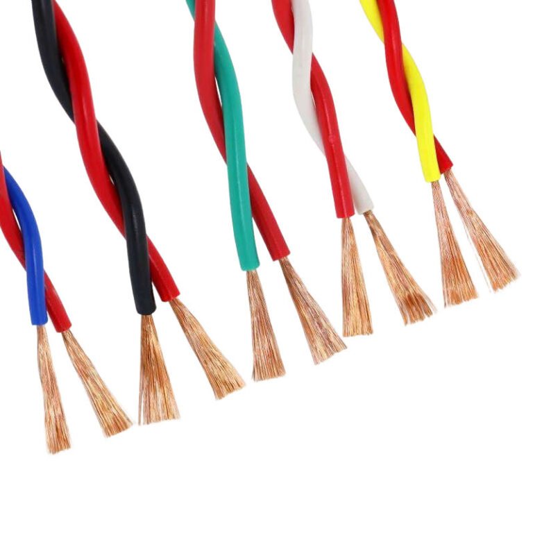
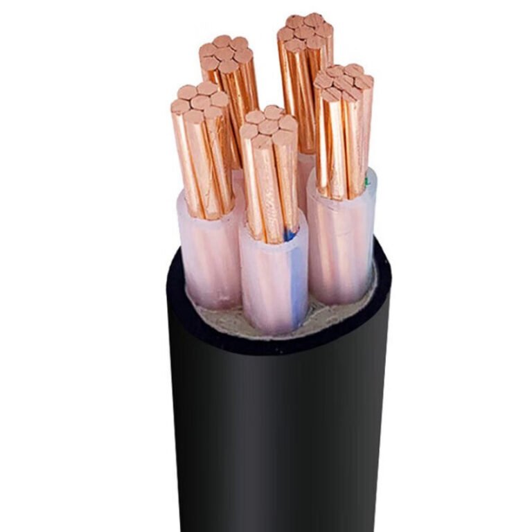
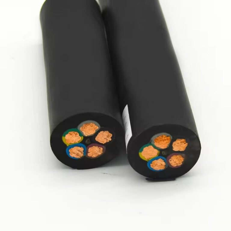
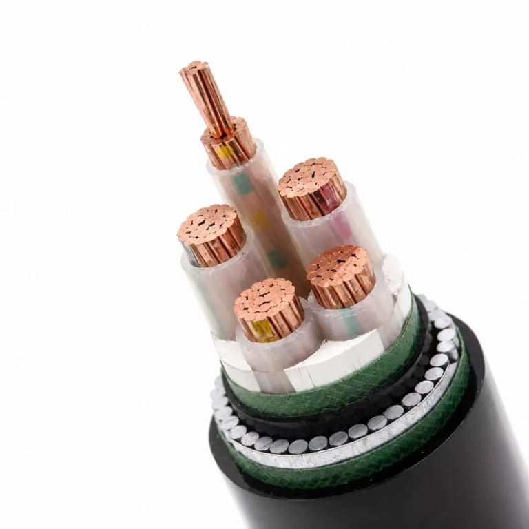
A failed buried feeder rarely gives a polite warning; it shows up as nuisance tripping, voltage drop, wet junction boxes, or a dead section of site lighting after the first heavy rain. Then the problem moves from electrical maintenance to excavation, outage planning, damaged paving, tenant complaints, and emergency purchasing. The practical answer is not one magic lifespan number, but matching the cable construction, protection method, joints, loading, and soil conditions to the service life you actually need.
Underground wire typically lasts about 25 to 40 years in direct-buried residential or light commercial service when the cable is correctly rated and installed. In duct banks or protected routes, well-specified power cable commonly reaches 40 to 60 years, while water ingress, bad joints, overload, or chemical exposure can cut life below 10 to 20 years.
The useful question is why one buried circuit quietly runs for decades while another fails before the building paint looks old. The difference is usually not luck. It is a chain of small decisions: insulation type, burial depth, conduit or direct burial, joint quality, drainage, conductor temperature, backfill, and whether anyone documented the route before the next contractor arrived with a trenching machine.
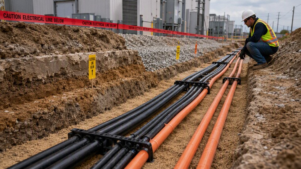
What actually ages buried cable?
Buried cable ages when its insulation, jacket, metallic screen, joints, or terminations lose the ability to control heat, voltage stress, moisture, and mechanical damage. Two cables installed in the same year can age completely differently because one is running cool in dry sand with good joints, while the other is sitting in a wet duct, overloaded every summer, with a marginal splice buried under asphalt.
The conductor itself is usually not the first part to “wear out” in a properly sized underground circuit. Copper and aluminum can give long service if kept dry, mechanically sound, and within temperature limits. The weak points are normally the insulation system, the outer sheath or jacket, the interfaces between materials, and the field-installed accessories. That is why cable history matters: pulling records, joint workmanship, load profile, soil condition, and fault history often tell you more than the manufacturing date.
Electrical stress
Electrical aging is mostly about how well the insulation controls electric field concentration over thousands of energized hours. In low-voltage residential circuits this is usually less dramatic, provided the cable is correctly rated and protected. In medium-voltage systems, electrical stress becomes one of the main life drivers because small defects can gradually become partial discharge sites or electrical trees.
Several details matter:
- Voltage rating and insulation thickness: A cable selected too close to the operating voltage has less margin for switching surges, temporary overvoltage, and system disturbances. Correct voltage class selection is not a paperwork exercise; it changes electric stress inside the insulation.
- Conductor screen and insulation screen quality: Medium-voltage cable relies on smooth semiconductive screens to distribute the electric field evenly. Poor screen interfaces, contamination, or eccentric insulation can raise local stress.
- Voids and inclusions in insulation: Tiny air voids, contaminants, or manufacturing defects can create localized discharge under high field. Reputable cable manufacturers control this through compound cleanliness, extrusion process control, and testing, but site damage can still ruin a good product.
- Partial discharge risk: Once partial discharge starts inside a void or at a poorly prepared termination, it slowly erodes insulation. It is not always an instant failure; it can sit quietly until one switching event finishes the job.
- Harmonics, transients, and overvoltage events: Variable speed drives, capacitor switching, lightning impulses, and poor grounding can add stress beyond a neat sinusoidal nameplate assumption. Harmonics are usually discussed as a heating issue, but steep-front transients can also stress insulation and terminations.
A buried cable with the correct voltage rating can still fail early if poor terminations create high local electrical stress.True
Voltage rating addresses the cable insulation design, but field-installed accessories must also control the electric field, seal moisture, and maintain proper contact pressure. A defective termination can become the failure origin even when the cable itself is well specified.
The trade-off is familiar in procurement: higher-rated cable, better screens, and tested accessory systems cost more upfront, but they buy electrical margin. That margin is worth far more on feeders where a single outage stops production or requires excavation under a finished yard.
Thermal stress
Heat is the quiet killer. Every ampere through the conductor produces I²R loss, and that heat has to move through insulation, jacket, bedding, duct or soil, then into the surrounding ground. If it cannot get out, conductor temperature rises, and polymer insulation ages faster through oxidation, hardening, and embrittlement.
The usual plant-floor suspects are not exotic:
- Sustained high load current: A feeder that looked adequate on the drawing may run near full load after extra equipment is added. Nobody updates the cable schedule, but the cable feels the extra heat every shift.
- Short-term overloads: Starting large motors, batch heaters, compressors, or welders may not trip protection, yet repeated thermal cycling expands and contracts materials at joints and terminations.
- High soil temperature: A route along a boiler house wall, under sun-baked pavement, or near steam condensate lines has less cooling capacity than a shaded route through damp native soil.
- Grouped circuits: Multiple loaded cables in one trench or duct bank heat each other. This is where derating tables and actual installation geometry matter.
- Poor heat dissipation: Dry sand, thermal backfill mistakes, air gaps in ducts, and compacted fill changes can all reduce ampacity.
- Harmonic-rich loads: Non-linear loads increase losses, especially in neutrals and conductors carrying triplen harmonics. It is not just a power-quality problem; it is a thermal aging problem.
A cable does not care what the spreadsheet says its load “should” be; it ages according to its actual conductor temperature over time. In practice, I like to see load logging before judging a suspect underground feeder. A clamp meter snapshot at 10 a.m. on a mild Tuesday can miss the summer afternoon peak that is doing the damage.
There is a trade-off between packing circuits tightly to save trenching cost and preserving thermal headroom. The preferred choice flips when civil work is expensive or space is tight, but then ampacity calculation, spacing, thermal backfill, and future load growth must be handled honestly. This conclusion stops holding if the circuit is lightly loaded with large conductor margin; in that case moisture or joint quality may dominate instead of heat.
Moisture and water trees
Water is not harmless just because the cable is “rated for underground use.” Moisture can migrate through damaged jackets, failed seals, poor duct drainage, imperfect splices, or wet soil. Over years, especially under electric stress, water can contribute to microscopic tree-like degradation paths in polymeric insulation systems such as XLPE.
Water trees are slow. That makes them commercially awkward: the cable may pass basic continuity and insulation checks for years, then begin showing intermittent faults or declining test results. In medium-voltage work, moisture barriers, metallic screens, water-blocking tapes, jacket integrity, and properly sealed accessories become important design details, not optional upgrades.
Common moisture entry routes include:
- Jacket cuts from pulling over rough duct edges.
- Splice bodies installed in wet pits or without proper cleaning.
- Duct banks with low spots that permanently hold water.
- Termination glands that were tightened unevenly or not matched to the cable diameter.
- Manholes where cable is repeatedly submerged after rain.
- Rodent damage or root pressure that opens a small path through the outer sheath.
A conduit can help with mechanical protection and replacement access, but it is not automatically a dry environment. I have opened ducts that behaved more like underground hoses: water at the low point, silt in the bend, and enough moisture to make every accessory suspect.
Mechanical stress
Many premature failures start before the circuit is ever energized. Pulling damage is easy to dismiss because the jacket “only has a few scuffs,” but abrasion, excessive pulling tension, and high sidewall pressure at bends can deform insulation or create jacket defects that later admit moisture.
Mechanical risks usually come from:
- Excessive pulling tension: Long duct runs, too many bends, or poor lubricant use can stretch or damage the cable.
- High sidewall pressure: Tight bends under load press the cable hard against the duct wall. This is especially risky for larger power cables.
- Sharp bend radius: Bending below the recommended radius can crack jackets, disturb screens, or stress insulation.
- Rock contact in direct burial: Stones against the jacket become pressure points after backfill compaction and settlement.
- Ground movement: Settlement, frost heave, and soil washout can bend or pull cable over time.
- Traffic and earthworks: Forklift yards, road crossings, trench rework, and post-installation digging can crush or nick cable.
- Vibration near heavy equipment: Crushers, presses, rail tracks, and large rotating machinery can transfer movement through ducts or supports.
Direct-buried cable in well-prepared bedding can be very reliable. Direct-buried cable thrown into a rocky trench with no warning tape, poor cover depth, and no route record is a future excavation fault waiting to happen.
Chemical and biological exposure
Soil chemistry is not uniform, and factory sites are rarely clean laboratory environments. Jackets and ducts may be exposed to hydrocarbons, oils, fuels, fertilizers, road salts, acids, alkalis, solvents, industrial effluent, landfill gases, and contaminated groundwater. Some exposures soften or swell polymer jackets; others accelerate cracking or attack metallic components.
Biological exposure is less glamorous but still expensive:
- Roots can enter damaged ducts or put pressure on cable routes.
- Insects may attack some materials or exploit existing openings.
- Rodents can chew jackets, especially where cables pass through accessible ducts, trays, pits, or building entries.
Material selection matters here. PVC, PE, XLPE, LSZH compounds, armoring, metallic sheaths, and duct materials all behave differently under chemical exposure. The practical step is to tell the cable supplier what the route actually crosses: fuel storage, fertilizer handling, wastewater trenches, coastal soil, landfill areas, or chemical processing zones. “Underground” is not a complete environment description.
Joint and termination weakness
The most misunderstood point is simple: a high-quality cable run can still fail early because the accessories were installed poorly. Factory-made cable is produced under controlled conditions. Field joints and terminations are made in a trench, pit, cabinet, substation, or windy yard by people working against time, moisture, dust, and access problems.
Weaknesses often come from:
- Wrong splice kit or termination type for the cable construction.
- Poor insulation screen removal on medium-voltage cable.
- Knife marks in insulation during preparation.
- Heat-shrink tubing overheated, under-heated, or contaminated before shrinking.
- Cold-shrink components installed out of sequence or on a dirty surface.
- Glands not matched to jacket diameter or armor type.
- Connector bolts or lugs tightened without proper torque control.
- Missing sealant, poor mastic overlap, or water paths left at the cable end.
- Inadequate stress control at medium-voltage terminations.
This is where a cheap installation can destroy an expensive cable. A torque wrench, clean wipes, proper training, and enough working time look boring on a purchase order, but they prevent a lot of buried trouble.
Why conduit is not always the safer choice
Conduit protects against shovels, rock, and some crushing forces, but it can create its own aging conditions. If the duct fills with water, traps heat, has sharp internal edges, or includes too many bends, it may expose the cable to moisture, higher conductor temperature, and pulling damage. Future fault location can also become harder if the route records are poor or ducts are congested.
The better question is not “direct buried or conduit?” It is:
- What mechanical hazards exist along the route?
- How wet will the route be during the worst season?
- Can the cable dissipate heat at design load and future load?
- Are joints avoidable, accessible, and installable under clean conditions?
- Is the cable construction matched to voltage, soil, chemical exposure, and maintenance access?
- Can the route be identified later before someone cuts across it with a backhoe?
The aging mechanism that wins is usually the one the design team failed to respect. Electrical stress, heat, water, mechanical abuse, chemicals, and accessory workmanship do not act separately for long; one small jacket cut becomes moisture ingress, moisture lowers insulation reliability, heat accelerates the damage, and a marginal joint becomes the point that finally lets go.
Installation conditions that shorten life
Poor installation can take a cable that should have lasted 40 years and make it a 10-year problem. The biggest life-shortening conditions are excess heat, trapped water, mechanical injury, bad pulling practice, and routes that cannot be inspected or repaired without major excavation. The cable data sheet matters, but the trench often decides the outcome.
A cable installed in a duct is always longer-lived than a direct-buried cable.False
Duct can improve mechanical protection and replacement access, but it can also hold water, reduce heat dissipation, increase pulling stress, and concentrate damage at bends or poorly sealed ends. Service life depends on the full route design, cable construction, drainage, loading, and installation quality.
Burial method categories that change the risk profile
Different underground methods fail in different ways, so I would not compare them only by first cost.
| Installation method | Main life advantage | Main life risk |
|---|---|---|
| Direct burial | Good heat transfer when bedding and backfill are right; no duct water trap | Vulnerable to rocks, excavation, rodents in some soils, and poor backfill |
| Rigid duct | Better mechanical protection and easier cable replacement | Water accumulation, difficult pulls, poor heat dissipation if overloaded |
| Flexible conduit | Useful for short transitions and awkward routing | Can snake, crush, trap water, or exceed bend limits if handled casually |
| Concrete-encased duct bank | Strong protection under roads and plant yards | Higher thermal resistance, grouped circuit heating, hard repair once poured |
| Cable tray transitioning underground | Clean plant interface when detailed well | Damage and moisture entry at the transition point |
| Horizontal directional drilling | Less surface disruption; useful under roads, rivers, and finished sites | Long pulls, unknown bore conditions, high sidewall pressure, hard fault access |
| Utility trench with multiple services | Efficient civil work and shared corridor | Separation conflicts, heat from other utilities, future excavation confusion |
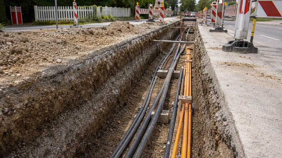
Direct burial is not automatically inferior. In a controlled route with selected bedding, correct depth, warning tape, and no aggressive soil, it can run cool and last well. The trade-off is that the cable itself takes more of the mechanical risk, so jacket toughness, armor, burial rating, and excavation controls become more important.
Duct systems shift the risk. They reduce direct shovel and rock damage, but they often create a wet pipe. I have opened “dry” plant ducts that poured water for several minutes because the route had one low point and no drain path. If the cable is not suitable for wet locations, or if joints sit in submerged pull boxes, the duct becomes a long bathtub.
Burial depth and physical protection
Burial depth should be set by the applicable electrical code, utility requirement, local authority, and site loading, not by a generic rule from a catalog. Frost depth, pavement thickness, vehicle axle loads, and the chance of future digging all matter. A residential lawn, a refinery pipe rack crossing, and a farm lane with deep ripping equipment are different installations.
The practical protection checklist should include:
- Required minimum cover under the current local code or project specification.
- Frost depth where ground movement can pull on cables, ducts, or terminations.
- Vehicle and equipment loading, especially under truck routes, forklift yards, cranes, and agricultural traffic.
- Warning tape or detectable tape placed high enough above the cable to be found before damage occurs.
- Marker posts, route markers, or as-built coordinates at direction changes, road crossings, and junctions.
- Protective tiles, slabs, or mechanical covers where future excavation is likely.
- Sand bedding or screened backfill around direct-buried cable to avoid point loading from rocks.
- Backfill compaction control so the route does not settle and leave ducts unsupported.
Bad backfill is a quiet cable killer. A sharp stone pressed into a polyethylene or PVC jacket may not cause an immediate failure, but it creates a stress point. Add seasonal ground movement, vibration from traffic, and moisture, and that small jacket cut becomes a path for water migration or corrosion of metallic screens and armor.
Soil thermal resistivity and cable temperature
Cable ampacity tables assume installation conditions. If the soil cannot carry heat away, the conductor runs hotter than the designer expected, even though the cable type and conductor size look correct on paper. That heat accelerates insulation aging through chemical and physical changes in the polymer; the exact rate depends on insulation material, operating temperature, loading profile, and wet/dry cycling.
Soil behavior is not intuitive:
- Dry sand can have poor thermal performance because air pockets resist heat flow.
- Compacted clay may conduct heat better when moist, but can crack and dry seasonally.
- Rocky fill creates voids and point contact, hurting both heat transfer and jacket protection.
- Soils with poor moisture retention may perform acceptably after installation and then degrade during summer drought.
- Concrete duct banks look robust but can trap heat when many loaded circuits are grouped together.
This is where undersized conductors and optimistic diversity assumptions punish the owner later. A cable that runs near its thermal limit every afternoon will age faster than one carrying the same annual energy at a lower peak temperature. The preferred choice can flip: direct burial in good native soil may run cooler than duct in a crowded bank, while duct may still be better where excavation risk dominates. The conclusion stops holding when site-specific thermal resistivity, load profile, and circuit spacing are not known; for critical feeders, those inputs should be calculated or tested rather than guessed.
Drainage, groundwater, and wet locations
Water is not always a problem by itself; the problem is water in the wrong cable construction, at the wrong accessories, for too long. Underground routes should be treated as wet unless there is strong evidence otherwise. Even “sealed” conduits breathe with temperature changes, and pull boxes that sit slightly below grade collect water after storms.
High-risk water conditions include:
- Standing water in ducts with no slope, drain, or sump strategy.
- Seasonal flooding that submerges handholes, joints, and cable ends.
- High water tables that keep the outer jacket continuously wet.
- Corrosive wet soil with salts, industrial contaminants, fertilizers, or low pH.
- Ducts entering buildings without proper sealing against water and gas migration.
- Pull boxes where splices lie below the normal water line.
For wet or flood-prone routes, buyers should verify whether the cable design includes suitable moisture resistance, water-blocking features, corrosion-resistant metallic layers where needed, and accessories rated for the same exposure. A good cable can still fail early if the termination kit, gland, or splice closure is the weak part.
Route geometry, pulling stress, and circuit grouping
Most underground cable damage happens before energization. Long pulls, tight bends, and crowded ducts can scrape jackets, stretch conductors, deform insulation shields, or damage screens. The installer may not see it unless the cable is tested after the pull.
Watch these geometry items closely:
- Minimum bend radius from the cable manufacturer, including larger radii during pulling where required.
- Total pulling distance and the number of bends between pull points.
- Intermediate handholes or pull boxes placed before pulling tension becomes excessive.
- Duct fill ratio, because a duct that looks adequate on diameter may still pull badly with multiple cables.
- Sidewall pressure at bends, especially for large single-core power cables.
- Foundation and wall transitions, where settlement and sharp sleeves can damage jackets.
- Road and rail crossings, where protection is better but replacement is harder.
- Spacing between parallel power circuits, since close grouping raises operating temperature.
Pulling lubricant must be compatible with the cable jacket. That sounds like a small purchasing detail until someone uses whatever drum is left in the store room and the jacket softens, swells, or loses slip halfway through a long duct pull. Use the lubricant, pulling tension limit, and pulling method stated by the cable or accessory supplier; do not let the crew improvise on a critical feeder.
Separation from other services
Shared corridors save civil cost, but they create electrical, thermal, chemical, and safety conflicts. A power cable beside a steam line or hot water pipe may operate in warm soil all year. A cable near chemical drains may see contaminants that were never considered in the jacket selection.
Give special attention to separation from:
- Gas lines, where electrical faults and excavation work introduce safety concerns.
- Steam and hot water pipes, which raise ambient soil temperature and reduce ampacity.
- Communications cables, where electromagnetic interference and maintenance access matter.
- Cathodic protection systems, which can create stray-current corrosion issues in metallic components.
- Chemical drains and process sewers, where leaks may attack jackets, armor, or accessories.
- Other power utilities, especially loaded medium-voltage circuits in the same trench.
Required spacing should come from the applicable code, utility standard, and project engineering documents. In a plant expansion, do not rely only on old drawings; I have seen abandoned lines, undocumented drains, and “temporary” conduits that became permanent obstacles.
Installation workmanship and records
Workmanship is the part buyers often under-specify because it is not as visible as conductor size or insulation rating. It deserves a line item in procurement documents and installation contracts.
Minimum good practice should include:
- Inspect reels before pulling for transit damage, broken lagging, or water exposure.
- Cap cable ends until termination so moisture does not enter during storage or rain delays.
- Use compatible pulling lubricant and calibrated pulling equipment where tension is critical.
- Avoid jacket cuts from rollers, duct edges, steel banding, and careless knife work.
- Seal duct ends against water, silt, rodents, and gas migration where required.
- Record route layout, depth, duct size, joint locations, crossing details, and photos before backfill.
- Perform post-installation insulation resistance tests and any specified sheath, VLF, or commissioning tests appropriate to the cable voltage and standard.
- Keep test reports, cable batch information, accessory details, and as-built drawings in the maintenance system.
A buried cable with no route record is not just an electrical asset; it is a future excavation hazard. The best time to document it is while the trench is still open, when a phone photo with a scale reference can prevent a fault, outage, or safety incident years later.
Cable constructions and realistic lifespans
A good underground cable is not just “copper with insulation around it.” Conductor metal, insulation chemistry, jacket material, armor, water blocking, voltage class, and termination quality all change the expected life. In ordinary procurement terms, marginal wet or harsh installations may run only 20 to 30 years, sound low-voltage systems often reach 30 to 50 years, and well-designed protected underground power systems can reach 40 to 60 years or more.
Conductor material: copper versus aluminum
Copper remains the conservative choice where space is tight, terminations are numerous, or maintenance quality is uncertain. It has higher conductivity than aluminum, so the same ampacity can usually be carried with a smaller conductor. That helps in crowded ducts, compact switchgear, machine feeders, and retrofits where bending space and gland size are already fixed.
Aluminum wins on weight and material cost, especially for long underground feeder runs, utility-style distribution, and large service entrances. The trade-off is size and termination discipline. Aluminum needs a larger cross-section for the same current, and the installer must use properly rated lugs, oxide inhibitor where specified, correct brushing practice if required by the connector manufacturer, and torque checked with a real calibrated wrench, not a fitter’s “good feel.” I have seen more trouble from poor aluminum terminations than from the aluminum conductor itself.
The main procurement differences are:
| Factor | Copper conductor | Aluminum conductor |
|---|---|---|
| Conductivity | Higher, smaller conductor for same ampacity | Lower, larger conductor needed |
| Weight | Heavier | Much lighter, useful on long pulls |
| Cost | Usually higher | Usually lower per installed ampere on large sizes |
| Terminations | More forgiving, but still needs correct lugs and torque | More sensitive to connector rating, oxide control, creep, and thermal cycling |
| Corrosion concern | Can suffer in aggressive environments, especially with dissimilar metals | Oxide layer and galvanic issues must be managed at joints |
| Best fit | Compact feeders, industrial equipment, critical circuits | Long feeders, utility-style runs, cost-sensitive large conductors |
Aluminum creep is not folklore. Under pressure and heat cycling, aluminum can relax more than copper, reducing contact pressure if the termination system is not designed for it. Modern listed aluminum connectors handle this, but only if the whole assembly is correct: conductor class, lug material, plating, torque, compound, and inspection interval.
Insulation systems that decide heat, moisture, and electrical life
PVC is common in low-voltage underground and building wire because it is economical, easy to process, and reasonably tough in general service. Its weakness is heat and long-term moisture-electrical stress compared with better thermoset insulations. For garden lighting, small services, and protected low-voltage routes it may be adequate; for industrial feeders that run warm for years, I would usually look harder at XLPE or EPR.
XLPE is widely used for power cables because it offers good dielectric strength, heat resistance, and aging performance. It is less rubbery than EPR, but it is a strong choice for 600 V, 1 kV, and many medium-voltage constructions when the cable is designed for wet locations and manufactured with proper cleanliness and shielding. In medium-voltage cable, insulation quality is not a cosmetic matter. Voids, contamination, poor shield interfaces, and water trees can all become partial-discharge or breakdown risks over time.
EPR is more flexible and generally more tolerant of handling abuse, vibration, and tighter installation conditions. Plants with portable substations, mining equipment, trailing applications, or feeders that get moved during shutdowns often prefer rubber-based constructions for that reason. The cost can be higher, and dimensions may differ, but it buys mechanical forgiveness.
PE has good moisture resistance and dielectric properties, but plain polyethylene has limitations in flame behavior and temperature performance depending on formulation. It appears more often as an outer jacket or part of a communication, control, or specialty construction than as the default industrial power insulation. Other materials, such as silicone rubber, fluoropolymers, or special thermoplastic elastomers, are selected for heat, oil, chemical, or flexibility needs rather than as universal underground choices.
Jackets, sheaths, and what the soil actually touches
The outer sheath is the part that lives in the trench, duct, manhole, or cable tray before burial. PVC jackets are common and cost-effective, with decent abrasion and flame performance depending on compound. PE jackets usually offer better moisture resistance and toughness in buried service, but flame performance must be checked when the route enters buildings, tunnels, substations, or confined infrastructure.
LSZH jackets are selected where smoke and acid gas generation matter, such as tunnels, transit systems, high-occupancy buildings, data facilities, and enclosed industrial galleries. They are not automatically the best direct-burial jacket. Some LSZH materials are less forgiving in wet soil, cold pulling, or abrasion unless specifically designed for that duty.
Nylon-coated constructions are often used where oil, gasoline, or abrasion resistance is needed around building wire types, subject to the applicable cable standard and code acceptance. In petrochemical plants, mines, wastewater sites, ports, and chemical areas, the jacket selection should be matched to the actual exposure:
- Hydrocarbons, diesel, lubricants, and cutting oils
- Acids, alkalis, salts, fertilizers, or process chemicals
- Wet clay, saline soil, or contaminated backfill
- Rodent activity and sharp aggregate
- Sunlight exposure during storage and staged installation
- Fire performance requirements at building entry or tunnel sections
A jacket that survives clean soil may fail early in oily, alkaline, saline, or rodent-active ground. That is why the soil and route survey belongs in the cable specification, not only in the civil drawings.
Armor and mechanical protection: useful, but not magic
Armor protects against crushing, impact, rodent damage, and rough handling. It does not fix undersizing, water-filled joints, excessive pulling tension, or overheated conductors.
Common options include:
- Steel wire armor: Good tensile and mechanical protection, often used in industrial, mining, and infrastructure power cables. It is strong but heavy and must be handled correctly at glands and bonding points.
- Steel tape armor: Useful for radial crush protection and some rodent resistance. It is less suited where high pulling tension or repeated movement is expected.
- Aluminum wire armor: Lighter and non-magnetic, useful where circulating losses or weight matter. Often considered for single-core AC cables where steel armor can create heating problems if not designed correctly.
- Corrugated metal sheath: Provides a strong moisture and mechanical barrier in some medium-voltage and utility-style cables. Bending radius, termination skill, and corrosion protection become more critical.
- Non-metallic protection: Glass yarns, aramid reinforcement, tough polymer layers, and rodent-resistant jackets can help where metallic armor is undesirable, such as certain corrosive areas or circuits with grounding constraints.
Armor has a commercial trade-off that buyers sometimes understate. It increases cable price, diameter, weight, bending radius, gland cost, and installation labor. For a straight feeder in a concrete-encased duct bank, a non-armored cable in a well-built duct may outlast an armored cable dumped into poor backfill. The preferred choice flips when the route is exposed to digging damage, rodents, mining movement, unstable ground, or direct burial without reliable civil protection.
Water-blocking and moisture barriers
Water rarely destroys a cable by simply touching the outside for a week. The long-term problem is migration. Once water enters at a damaged jacket, open end, poor joint, or flooded manhole, it can travel along conductor strands, screens, fillers, and bedding layers. In medium-voltage cables, moisture combined with electrical stress can promote water treeing in susceptible insulation systems.
Useful water-control features include:
- Longitudinal water-blocking tapes that swell when wet
- Swelling powders in bedding or screen areas
- Water-blocked conductors to reduce strand-to-strand water travel
- Metallic moisture barriers, such as lead sheaths or corrugated metallic layers, where specified
- Laminated sheaths that combine polymer and metallic foil barriers
- Heat-shrink, cold-shrink, resin, or molded terminations rated for the voltage, environment, and cable construction
Water blocking is not a license to install with open cable ends in the rain. On a busy site, I like to see cable ends capped during storage, after cutting, and overnight. It is a cheap habit compared with fault finding a year later in a flooded pull box.
Voltage class and application differences
Low-voltage underground building wire, 600 V or 1 kV power cable, medium-voltage distribution cable, control cable, instrumentation cable, solar cable, and street lighting cable are not interchangeable just because they all disappear into the ground.
For procurement, separate them by duty:
- Low-voltage building wire: Must match the wiring method, wet-location rating, conduit or direct-burial approval, and local electrical code.
- 600 V or 1 kV power cable: Used for feeders, motors, panels, and site distribution; ampacity, short-circuit rating, insulation temperature, and jacket environment matter.
- Medium-voltage distribution cable: Requires insulation shields, metallic screens or concentric neutrals, tested accessories, proper grounding, and skilled jointing.
- Control cable: Usually carries signals for starters, valves, interlocks, and auxiliary circuits; jacket toughness and core identification are often more valuable than high ampacity.
- Instrumentation cable: Needs shielding, pair or triad construction, noise control, and sometimes intrinsically safe circuit identification.
- Solar cable: Must handle UV exposure, heat, DC service, and connector compatibility before any buried portion is considered.
- Street lighting cable: Often faces wet handholes, repeated maintenance access, rodent damage, and many small joints, so joint quality can dominate cable quality.
Realistic lifespan bands by construction
These ranges are planning bands, not warranty promises:
| Cable construction and environment | Practical life expectation |
|---|---|
| Marginally protected cable in wet soil, poor joints, aggressive backfill, or overloaded circuits | Roughly 20 to 30 years, sometimes less |
| Correctly selected low-voltage underground cable in conduit, duct, or suitable direct burial with sound terminations | About 30 to 50 years |
| Well-specified underground power cable in protected routes, with water blocking, proper accessories, and controlled loading | Commonly 40 to 60 years or more |
| High-risk installations with water ingress, chemical attack, mechanical damage, or undersized conductors | Can fall below 10 to 20 years |
These bands stop being useful when the circuit is running near thermal limits, the route floods regularly, joints are unverified, or the cable type is only vaguely described. At that point, life expectancy has to be estimated from load profile, soil thermal resistivity, installation depth, duct fill, joint records, insulation test history, and the actual cable datasheet.
Procurement warning: “direct burial” is not the full specification
A cable label that says suitable for direct burial is only one qualification; it is not a complete engineering approval. Before issuing a purchase order, verify:
- Voltage rating and system grounding compatibility
- Maximum conductor and insulation temperature rating
- Wet-location or water-resistant rating required by the installation
- Direct-burial, duct, tray, tunnel, or building-entry acceptance
- Flame, smoke, and halogen requirements for exposed or indoor sections
- UV resistance if the cable will sit outdoors before burial
- Chemical compatibility with soil, groundwater, oils, fuels, or process contaminants
- Armor bonding, screen grounding, and short-circuit withstand requirements
- Minimum bending radius and pulling tension limits from the manufacturer
- Approved glands, joints, terminations, and repair kits
- Local code acceptance and third-party certification required by the project
A cable marked for direct burial will always achieve a 40-year underground service life.False
Direct-burial marking confirms suitability for a defined installation method under specified standards, but service life still depends on loading, soil conditions, water ingress, mechanical damage, joint quality, chemical exposure, and whether all project-specific ratings are met.
Sizing, standards, and procurement checks
Cable life is largely locked in before the trench is opened. For industrial, utility, and bulk procurement projects, the buying specification should prove three things: the cable is electrically sized for the duty, mechanically and environmentally suited to the route, and manufactured/tested under standards the project can actually verify. A low unit price does not help much if the installed cable becomes the cheapest part of a very expensive failure.
Ampacity and derating are not just cable-size exercises
Conductor cross-sectional area is only the starting point. The ampacity printed in a catalog usually assumes defined installation conditions; once the cable is buried, installed in duct, grouped with other circuits, or run through warm soil, the allowable current can change materially. That is where many underperforming underground systems are born.
For a proper sizing review, the engineer or buyer should confirm:
- Load current and duty cycle
A pump feeder running near full load for 18 hours a day ages insulation differently from a lightly loaded standby circuit. Continuous industrial loads need more conservative thermal review than intermittent residential services. - Soil thermal resistivity
Dry sand, rocky backfill, compacted native soil, and wet clay do not remove heat the same way. Poor thermal backfill raises conductor temperature, which accelerates insulation aging. In practice, this is one of the easiest variables to ignore because the purchasing team may never see the geotechnical report. Burial depth and installation method
Deeper burial may improve mechanical protection but can reduce heat dissipation depending on soil and route conditions. Cables in ducts usually run hotter than directly buried cables because the duct wall and trapped air add thermal resistance.Grouping and duct fill
Multiple loaded circuits in the same trench or duct bank heat each other. A cable that is acceptable as a single run may be undersized in a crowded route.Ambient ground temperature and seasonal effect
Plants in hot climates, asphalt-covered routes, and areas near steam lines or process heat need site-specific derating. I have seen otherwise adequate feeders run hot simply because the trench passed beside a buried hot-water line nobody included in the drawing set.Voltage drop and motor starting
Long underground runs may satisfy ampacity but still give unacceptable voltage drop, especially for motors, compressors, welders, and distant distribution panels.Future expansion
If the plant owner expects another production line, charger bank, irrigation pump, or utility tie-in later, oversizing the conductor or installing spare duct can be cheaper than reopening the route.
The trade-off is capital cost versus operating margin. Larger conductors cost more upfront and can be harder to pull, terminate, and store, but they reduce thermal stress, voltage drop, and future replacement risk. The conclusion stops holding where pulling tension, conduit fill, termination lug range, short-circuit coordination, or budget limits make the larger size impractical; those constraints need checking before the purchase order is released.
Voltage rating, insulation level, and fault behavior
Correct voltage class is not a paperwork detail. It defines insulation thickness, electric stress, test voltage, impulse withstand expectations, and compatibility with joints and terminations. Long cable life depends on keeping the dielectric system inside its intended electrical operating envelope.
For medium-voltage and higher-risk low-voltage systems, specify:
- System voltage and maximum operating voltage
- Cable voltage grade and insulation category
- Grounding arrangement, such as solidly grounded, resistance grounded, or ungrounded operation
- Expected earth-fault duration
- Short-circuit current and clearing time
- Impulse withstand requirement where applicable
- Compatible joints, terminations, screens, and earthing hardware
The mechanism is straightforward: higher electrical stress, partial discharge at defects, moisture at interfaces, or repeated overvoltage events can damage insulation long before the conductor itself has any problem. A cable may pass factory testing and still have reduced field life if installed on a system with fault characteristics outside the insulation design assumptions.
Selecting underground cable by conductor size alone is enough to predict service life.False
Conductor size affects temperature and voltage drop, but long-term service life also depends on insulation system, sheath and armor selection, water protection, installation method, jointing quality, system grounding, and verified test documentation.
Standards and documentation that belong in the purchase file
The applicable standard depends on project location, utility practice, voltage class, and customer requirements. A serious specification should name the recognized standard or code framework, not use vague language such as “export quality” or “international standard.”
Common reference families include IEC, BS, EN, ASTM, ICEA, UL, CSA, and relevant national electrical codes or utility specifications. The buyer should also identify whether the requirement is for design compliance, third-party certification, factory test records, or project-specific inspection.
Ask for documentation that can be tied to the exact cable supplied:
| Procurement check | What to request | Why it matters in service |
|---|---|---|
| Type test evidence | Type test reports to the specified standard | Confirms the design has been qualified, not just produced once |
| Routine electrical tests | High-voltage test records, spark testing where applicable | Screens manufacturing defects before shipment |
| Conductor verification | Conductor resistance, material grade, strand construction | Confirms ampacity and voltage-drop assumptions |
| Insulation and sheath checks | Thickness, eccentricity, dimensional inspection | Reduces weak points and premature jacket failure |
| Fire performance where needed | Flame or fire-related test reports for the specified application | Required in tunnels, buildings, plants, and regulated markets |
| Traceability | Batch number, drum number, inspection record, production date | Helps isolate issues and support repeat orders |
For bulk procurement, traceability is not just administrative neatness. If one drum is damaged, one production lot has a dimensional concern, or one shipment is exposed to poor storage conditions, drum-level records let the project team contain the problem instead of treating every installed circuit as suspect.
Project data the supplier needs before quoting
A usable cable inquiry should include enough information for the manufacturer and project engineer to price the same product the site actually needs. At minimum, include:
- Conductor material: copper or aluminum
- Conductor class and flexibility requirement
- Core count and cross-sectional area
- Rated voltage and system grounding details
- Insulation material and required standard
- Inner sheath, outer sheath, and sheath color
- Armor type, if required
- Water-blocking requirement: conductor, screen, or overall construction as applicable
- Screen or shield construction for medium-voltage cable
- Drum length tolerance and maximum drum size
- Cable marking language and content
- Packing, palletizing, and export requirements
- Color coding or core identification
- Installation environment: direct burial, duct, tray, tunnel, wet area, chemical exposure, traffic load, termite or rodent risk where relevant
- Required certificates, inspection plan, and shipment schedule
A common buying mistake is to send only “4-core 185 mm² cable” and ask for the lowest price. That leaves too many expensive variables undefined: insulation grade, sheath compound, armor, water protection, flame requirement, standard, certification level, and whether the cable will match the joints and terminations already selected.
Supplier capability and total cost of ownership
For long-life underground cable, supplier selection should weigh manufacturing consistency and technical support alongside price. A factory with stable production capacity, engineering review capability, export documentation experience, and repeat-order discipline is usually easier to manage across multi-phase projects than a one-off low bidder.
Shandong Jinda Special Cable Group Co., Ltd., established in 1987, has five production bases, about 470,000 m² of manufacturing space, more than 1,000 employees, and an integrated system covering R&D, production, sales, technical support, and after-sales service. For buyers managing international cable packages, those capabilities matter because underground projects often involve staged releases, mixed cable types, changing delivery windows, and documentation demands from consultants, utilities, or customs authorities.
The commercial comparison should include:
- Initial cable price
- Trenching, duct, bedding, and reinstatement cost
- Pulling, jointing, termination, and testing labor
- Outage cost if the circuit fails
- Fault location and excavation cost
- Safety exposure during repair
- Lost production or service interruption
- Replacement lead time
- Compatibility with future expansion phases
Underground cable is one of those purchases where saving a few percent on material can create a much larger maintenance liability later. The better procurement question is not “What is the cheapest cable with this conductor size?” but “Which specified, tested, documentable cable gives the required service margin in this route, on this system, for the lowest lifetime risk?”
Warning signs and inspection methods
Treat underground cable inspection as a fault-finding sequence, not a walk-by visual check. The first signs often appear at the load, the breaker, or an exposed termination long before anyone sees a damaged buried section.
Operational symptoms worth investigating
Visible cable damage is the easy case. The harder case is a feeder that is still working, but only just. Watch for patterns such as:
- Nuisance breaker trips or repeated fuse operation, especially after rain, heavy load, or temperature swings.
- Voltage drop under load, seen as slow motor starting, dimming lighting, weak heaters, or low control voltage at remote equipment.
- Flickering lights and unexplained equipment resets, particularly on long buried runs feeding panels, pumps, gates, refrigeration units, or outdoor process equipment.
- Motor overheating, because poor voltage balance or excessive conductor resistance pushes current up and shortens motor insulation life.
- Intermittent power loss, where vibration, soil movement, or moisture changes disturb an already weakened joint.
- Increased leakage current or ground fault alarms, which may point to insulation tracking, water ingress, damaged sheath, or contaminated terminations.
Do not assume every trip is a “bad cable.” A breaker with the wrong curve, a wet motor junction box, a loose lug, or a nuisance residual-current device can look similar from the control room. The useful clue is repeatability: load-related symptoms point toward conductor sizing, resistance, or termination heating; weather-related symptoms often point toward moisture paths, damaged jackets, flooded ducts, or compromised splices.
Physical clues at accessible points
Most buried cable failures reveal themselves where the cable stops being buried. Inspect every accessible transition before blaming the underground span:
- Terminations and lugs: discoloration, melted insulation, brittle tape, loose hardware, overheated heat-shrink, or a burnt varnish smell.
- Pull boxes, junction boxes, and service pedestals: standing water, mud, insects, missing seals, corroded terminals, or covers that no longer seat properly.
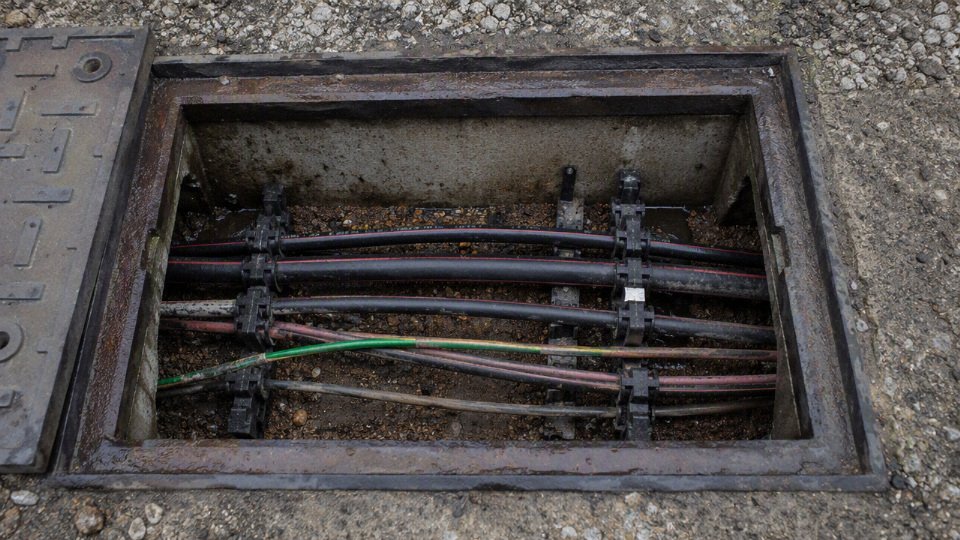
- Manholes and handholes: flooded ducts, sediment, damaged racks, sharp bend points, and cable jackets rubbed against concrete edges.
- Cable glands and equipment entries: cracked seals, missing compression, wrong gland size, exposed armor, or water trails into the enclosure.
- Exposed transitions: UV-cracked jackets, crushed conduits, split flexible conduit, or cable unsupported at a wall penetration.
- Outer jacket condition: cracking, swelling, cuts, abrasion, chemical softening, or rodent marks.
Moisture is especially deceptive. A small seep at a gland can wick along bedding, screen wires, or armor and create a leakage path some distance away from the visible entry point. Once leakage current starts, local heating and electrical stress can accelerate insulation aging; the cable may test acceptably when dry and fail after the next storm.
Environmental clues along the route
A cable route changes over 20 or 30 years. The drawing in the cabinet may say “landscape strip,” while the current site has forklifts, asphalt repairs, and a new drain line crossing the feeder.
Check for:
- Flooded ducts or manholes, especially after seasonal rain or snowmelt.
- Subsided trenches, sink marks, or disturbed backfill showing soil movement.
- Cable exposed by erosion, washouts, ditch cleaning, or landscaping work.
- Rodent activity near service pedestals, farm buildings, pump houses, and outdoor cabinets.
- Nearby excavation damage, including old backhoe scars, repaired conduit, or undocumented utility work.
- Chemical spills or aggressive soil exposure, such as fuel, solvents, acids, fertilizers, saltwater, or process effluent.
- Tree root intrusion, which can deform ducts, pull joints, or trap moisture.
- New heavy traffic over old routes, including truck yards, container handling areas, temporary cranes, or compactors.
The trade-off with underground routes is clear: burial protects against casual physical contact and weather, but it hides slow mechanical and environmental damage. Once the surface conditions change, the original cable selection may no longer match the duty.
Basic electrical tests
Basic testing should compare the cable against itself, its design documents, and commissioning records. A single number without temperature, cable length, test voltage, and previous results is often less useful than people think.
Common checks include:
- Continuity testing to confirm each conductor is intact and correctly landed.
- Insulation resistance testing with a suitable megohmmeter, selected for the cable voltage class and manufacturer guidance.
- Conductor resistance checks to identify high-resistance joints, undersized replacements, corrosion, or partial conductor damage.
- Ground fault testing to confirm protective devices see and clear faults as intended.
- Polarity checks on single-phase and control circuits, especially after repairs or extensions.
- Comparison against baseline commissioning data, which is one of the strongest practical indicators of deterioration.
A declining insulation resistance trend is more meaningful than a one-off reading taken with unknown temperature, moisture, and cable length conditions. In practice, I want test sheets to show date, ambient condition, cable identification, test voltage, duration, measured values, and the person responsible. A handwritten “OK” on a panel door is not a maintenance record.
Advanced diagnostics for higher-risk circuits
For medium-voltage feeders, critical production circuits, long duct-bank runs, or cables with a failure history, advanced diagnostics can find defects that a simple continuity check will miss:
| Method | What it helps detect | Practical caution |
|---|---|---|
| Very low frequency testing | Gross insulation weakness in many power cable systems | Test level and duration must match cable type and standard practice |
| Tan delta testing | Insulation aging, water treeing trends, dielectric loss | Best used comparatively across phases and over time |
| Partial discharge testing | Voids, sharp defects, poor joints, termination stress | Interpretation needs experienced personnel and suitable sensors |
| Time domain reflectometry | Approximate distance to opens, shorts, impedance changes, damaged sections | Accuracy depends on cable data, reflections, and route complexity |
| Sheath integrity testing | Jacket or metallic sheath damage allowing moisture entry | Particularly useful before backfilling or after civil work |
| Thermal imaging at terminations | Hot lugs, imbalance, overloaded connections | Must be done under representative load |
| Online monitoring | Leakage, temperature, or partial discharge trends on critical circuits | Cost is justified only where downtime or safety consequences are high |
Advanced testing has a cost and outage burden, and some offline tests can stress already aged insulation if specified poorly. The preferred choice flips when the circuit feeds a kiln, data center, mine pump, hospital load, or production bottleneck; then planned diagnostics are usually cheaper than an unplanned dig-up at 2 a.m.
Inspection frequency
Set inspection intervals by risk, not by a universal calendar rule. A lightly loaded residential direct-buried branch circuit and a 15 kV plant feeder under a wet truck yard do not deserve the same plan.
Use these factors to set the interval:
- Voltage class and fault energy
- Load criticality and production impact
- Cable age versus expected service life
- Known wet, corrosive, or mechanically active environment
- History of trips, repairs, splices, or excavation near the route
- Consequences of downtime, fire, shock exposure, or environmental release
- Availability of baseline test data
Low-risk circuits may only need inspection during scheduled maintenance, panel work, or site changes. Older, wet, heavily loaded, or critical circuits deserve planned testing and documented trending, especially before seasonal peaks or shutdown windows.
Underground cable diagnosis must be performed by qualified electrical personnel using lockout procedures, properly rated test equipment, arc flash precautions, verified absence of voltage, and applicable local electrical safety rules. The inspection can start with symptoms and visible clues, but any decision to re-energize, hipot, excavate, or defer repair belongs in a controlled electrical work process, not an informal maintenance guess.
Extending service life after installation
A buried cable that was correctly selected and installed can often gain useful years from disciplined operation and maintenance, but maintenance cannot reverse insulation damage, water-treeing, overheated joints, or crushed sections. The practical goal is to slow avoidable aging, catch weak accessories early, and know when a feeder has moved from “maintain” to “replace.” That line is especially important on critical production feeders where one trip can stop a line, freezer plant, pump station, or data hall.
Manage load before the cable becomes the heater
Load is the first thing I check when an “old cable problem” shows up, because many underground failures are really thermal problems with an age label attached. Insulation aging accelerates with temperature: higher conductor current creates I²R losses, heat has to escape through bedding, duct, soil, or concrete, and any bottleneck at a joint or lug runs hotter than the straight cable.
Practical checks should include:
- Monitor actual current, not just nameplate assumptions. Use metering, temporary loggers, or power quality instruments over representative shifts. A cable that looks fine at 10 a.m. may be overloaded during compressor start sequences, seasonal irrigation pumping, or evening production peaks.
- Avoid chronic overload. Short overloads may be acceptable if the cable and protection were designed for them, but running near or above ampacity every day shortens insulation and accessory life.
- Balance three-phase loads. High current on one phase heats one conductor and can overload neutrals in systems with significant single-phase or non-linear loads.
- Evaluate harmonic heating. Drives, rectifiers, UPS systems, LED lighting banks, and welders can raise RMS current and neutral current. The cable does not care that the fundamental load looks modest on a spreadsheet.
- Review every equipment addition. Spare breaker space is not spare cable capacity. Before adding a chiller, CNC line, EV chargers, pumps, or a larger transformer, check the feeder rating, installation method, derating factors, and protection settings.
The trade-off is capacity versus temperature margin. Using more of an existing feeder can avoid capital spend this year, but it consumes thermal life and makes later expansion harder. The preferred choice flips when the feeder has tested well, has documented thermal margin, and supplies a non-critical load; it does not flip because nobody wants to open the trench.
Keep moisture away from accessories
Underground cable jackets are designed to tolerate damp soil, but many failures start at places where the cable system is interrupted: terminations, splices, glands, handholes, manholes, cabinets, and pull boxes. Standing water brings contaminants, corrosion, tracking risk, and freeze-thaw movement in cold sites. In practice, I have seen more trouble from a cracked cabinet gland and a missing drain plug than from the cable run itself.
Maintenance crews should:
- Keep handholes and manholes drained; do not let them become permanent sumps.
- Re-seal cabinets, junction boxes, and termination enclosures after inspection work.
- Replace hardened, split, or poorly fitted cable glands.
- Check that ducts are sealed where water, rodents, or silt can enter.
- Keep vulnerable terminations above predictable water levels where the installation allows it.
- Use termination and joint kits rated for the wet, chemical, UV, or temperature exposure actually present on site.
Do not treat water as harmless just because “it has always been wet down there.” If water reaches a compromised screen cutback, lug, stress cone, or splice seal, the failure clock can speed up quickly.
Reassess thermal conditions when the site changes
Buried cable ratings are based on heat leaving the conductor. Change the surroundings and the rating may change too. Adding asphalt over a cable route, compacting soil differently after civil work, installing steam lines nearby, filling a tray or duct bank with extra circuits, or modifying an enclosure can all reduce cooling.
Before adding parallel circuits into an existing duct bank, get an ampacity review rather than relying on the old one-line diagram. Heat from neighboring circuits accumulates, and ducts that were comfortable with two loaded feeders may run hot with four. The same applies after paving yards, changing landscaping, enclosing outdoor cabinets, or routing exhaust air near terminations. The boundary here is simple: these actions extend life only while the cable still operates within its verified electrical, thermal, mechanical, and environmental limits.
Protect the route from excavation damage
Mechanical damage is one of the least glamorous and most expensive causes of premature underground cable failure. A nicked jacket, scraped screen, crushed duct, or bent splice may survive the first insulation test and then fail months later in rain or peak load.
A workable excavation-control program includes:
- Current route drawings with depths, duct bank widths, joint locations, and crossing details.
- Detectable warning tape or marker systems above direct-buried routes.
- Updated utility maps after every repair, reroute, or new service.
- Mandatory locate procedures before digging, fencing, trenching, pile driving, or installing signposts.
- Controls for third-party contractors, especially during weekend civil work when the electrical supervisor is not watching.
- Photographs of open trenches before backfill; these are cheap insurance when nobody remembers where the bend was placed.
Maintain accessible accessories and records
Accessible parts deserve scheduled attention because they are often the weakest part of the underground system. Inspect terminations for tracking, discoloration, cracked stress-control parts, corrosion, swelling, oil or compound leakage where applicable, and signs of overheating. Re-torque bolted connections only where the equipment manual or site procedure permits it; careless re-torqueing can damage hardware or disturb a connection that should have been tested first. Check grounding and bonding continuity, especially after enclosure replacement or civil repairs.
Good records make maintenance decisions defensible:
- Cable data sheets and construction details.
- Factory test reports and certificates supplied with the cable.
- Installation test results, including method, voltage, duration, and ambient conditions.
- Route drawings, pull records, bend locations, splice locations, and duct assignments.
- Maintenance history, water ingress events, thermal findings, and fault records.
- Load studies and changes in connected equipment.
Replacement planning belongs in the same file, not in a panic after a fault. Critical feeders should have triggers based on insulation test trends, partial discharge findings where applicable, repeated accessory failures, overload history, moisture exposure, and business continuity risk. Extending service life is good engineering; using maintenance paperwork to postpone a known end-of-life feeder is just deferred downtime.
Frequently asked questions
Can underground wire last 100 years?
Yes, a few underground cables can remain energized for something approaching 100 years, usually where loading is light, temperature is modest, moisture is controlled, and the route has not been disturbed. I would not use 100 years as a normal design assumption for residential, commercial, or industrial underground wiring.
For planning purposes, treat century-life cable as an exception found after inspection and testing, not a procurement target. Most owners should design around the realistic service ranges for the cable type, protection method, soil conditions, joints, and operating load.
Does conduit make underground wire last longer?
Conduit often helps, mainly by reducing excavation damage, rock pressure, and direct soil contact. It also makes replacement easier if the route was installed with sensible bend radius, usable pull points, and no crushed sections.
That said, conduit is not magic protection. A duct that holds water, overheats a heavily loaded cable, has sharp elbows, or was installed with burrs and poor pulling practice can shorten cable life. In plants, I have seen “protected” cables fail early because a duct bank stayed flooded all winter and nobody had a drainage plan.
Is direct-burial cable safe without conduit?
Properly rated direct-burial cable can be safe without conduit when it is installed to the applicable electrical code, manufacturer instructions, burial depth, bedding, warning tape, and mechanical protection requirements. The phrase “direct burial” must be on the correct cable specification, not assumed from jacket thickness.
The weak points are usually not the straight cable run. They are risers, terminations, splices, driveway crossings, rocky backfill, and places where future digging is likely.
How do I know if old underground wire needs replacement?
Use more than age. Review:
- Installed age and whether records are reliable
- Cable type, insulation material, voltage rating, and burial method
- Load history, especially overloads or seasonal peak operation
- Visible jacket, termination, and enclosure condition
- Insulation resistance, polarization index, tan delta, VLF, or other test results where appropriate
- Fault history, nuisance trips, heating, or moisture evidence
- Consequence of failure: safety risk, production loss, pump outage, freezer loss, tenant impact
An old feeder serving a garden light is a different decision from an old feeder serving a lift station or production line.
Which lasts longer, copper or aluminum underground wire?
Conductor metal alone does not decide underground cable life. Copper and aluminum can both last a long time when the insulation system, sheath, terminations, loading, and corrosion control are right.
Copper is less sensitive to some termination abuse and has higher conductivity for the same cross-section. Aluminum can be reliable and economical, especially in larger feeders, but it needs compatible lugs, correct torque, oxide inhibitor where specified, and thermal cycling discipline. In practice, bad joints kill more cables than the choice between copper and aluminum.
What is the biggest cause of early underground cable failure?
The leading early-failure causes are moisture ingress, mechanical damage, poor splices or terminations, incorrect cable selection, and overheating. They often arrive in combinations: a nicked jacket lets water in, the wet area tracks electrically, then a marginal splice becomes the fault point.
Undersized conductors are another common commercial mistake. Heat accelerates insulation aging, and once the cable spends years running hot, the damage is not reset by reducing the load later.
Can damaged underground wire be repaired?
Localized faults can sometimes be repaired with a proper underground splice kit installed by qualified technicians. The repair has to match the cable voltage class, insulation type, conductor material, environment, and code requirements.
Repeated faults are a different matter. If tests suggest widespread insulation degradation, water-treeing, brittle jacket, or multiple wet sections, patching one fault may only buy a short interval before the next outage.
A single successful splice does not prove the rest of an old underground cable is healthy.True
A splice can restore one localized fault, but the remaining cable may still have aged insulation, moisture contamination, thermal damage, or other hidden defects that require testing and risk review.
Should I replace underground wire before it fails?
Preventive replacement is often justified where failure cost is high, access is difficult, test results are declining, cable records are poor, or the route is exposed to flooding, chemicals, vibration, or repeated excavation. Waiting for failure may look cheaper until it happens at night, in rain, with production stopped and no spare cable on site.
For non-critical circuits, testing and monitoring may be enough. For critical feeders, replacement should be planned like any other asset renewal: confirm the load, inspect the route, choose the right cable construction, and schedule the outage before the cable chooses it for you.
Verify your underground cable specification
Underground wire life is not a fixed calendar number; it is the result of correct cable construction, correct installation, controlled loading, environmental protection, and verifiable quality. A cable that is suitable on paper can still fail early if it is pulled through a wet duct with poor joints, overloaded every summer, or bought without matching the actual burial condition.
Before purchasing underground cable, check the specification against the job rather than against a generic catalog line. At minimum, confirm:
- Voltage grade: match the system voltage, grounding method, and any project standard requirement, especially for medium-voltage feeders.
- Conductor size: verify ampacity after derating for soil temperature, duct grouping, burial depth, and continuous load.
- Conductor material: copper or aluminum should be selected with termination compatibility, voltage drop, pulling weight, and budget in mind.
- Insulation type: confirm suitability for the operating voltage, thermal class, and wet underground service.
- Outer sheath: check resistance to moisture, abrasion, sunlight during storage, oils, chemicals, or site-specific contaminants.
- Armor: specify armor where mechanical protection, rodent risk, mining service, industrial yards, or direct burial exposure justify it.
- Wet-location suitability: do not assume all outdoor-rated cable is fit for long-term wet ducts or saturated soil.
- Direct-burial or duct suitability: these are not the same installation condition; pulling friction, crush risk, drainage, and repair access differ.
- Standards and certification: align the cable with the required national, IEC, utility, or project standard before price comparison.
- Drum length: check route length, spare allowance, pulling section limits, and joint minimization.
- Installation method: trench, duct bank, tray-to-burial transition, horizontal directional drilling, and riser protection all change the practical cable choice.
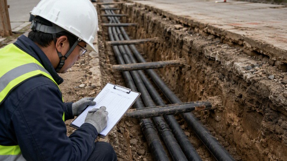
For existing underground installations, the verification job is different. You are trying to decide whether the cable can remain in service, needs closer monitoring, or should be planned for replacement. Gather:
- Cable age and any known installation records.
- Route drawings, even if they need field verification with a locator.
- Load measurements, including seasonal peaks and motor-starting duty.
- Fault history, nuisance trips, repairs, and joint failures.
- Visible termination condition, including heat marks, cracked stress control, corrosion, loose lugs, or water tracking.
- Insulation resistance trend, not just one isolated test value.
- Moisture exposure, such as flooded manholes, low duct points, or damaged gland seals.
- Criticality of connected equipment, because a feed to a spare pump is not the same risk as a main production line or fire pump supply.
Ask for engineering support when the route or duty is outside normal residential or light commercial practice: unusual soil, long runs, high load, medium-voltage service, corrosive environments, grouped ducts, renewable energy sites, mining, petrochemical plants, export projects, or multi-phase procurement. Grouped ducts are a common trap; they make the installation neat, but heat cannot leave the cable as easily, so the same conductor size may run hotter and age faster.
If you are planning underground cable procurement or replacement, share the project voltage, load, route length, installation environment, required standards, and expected service life. Jinda’s technical and sales teams can review those details against available cable constructions and help verify a practical specification and quotation before you commit to drums, accessories, and installation work.