Underground wire mistakes usually show up after the trench is backfilled: lights dim, pumps start hard, heaters underperform, or a breaker keeps getting blamed for what is really voltage drop. By then the cheap part of the job is over, and the expensive part is re-trenching, upsizing cable, replacing nuisance-damaged equipment, or failing inspection. The right way to size a 10/2 underground run is to separate ampacity, voltage drop, burial method, and local code before anyone rents the trencher.
For 10 AWG copper underground cable, a practical 3% voltage-drop limit is roughly 60 ft on a 30 A, 120 V load, or about 120 ft on a 30 A, 240 V load. At 20 A, those distances rise to about 90 ft and 180 ft, before temperature, conduit fill, and local code checks.
That answer is useful, but it is not the whole job. A 30 A well pump, a garage sub-feed, a mini-split, and a shed outlet circuit can all put very different stress on the same 10/2 cable, and burial depth rules do not solve voltage drop. The details below are where the safe distance either holds up or quietly falls apart.
What 10/2 underground wire means
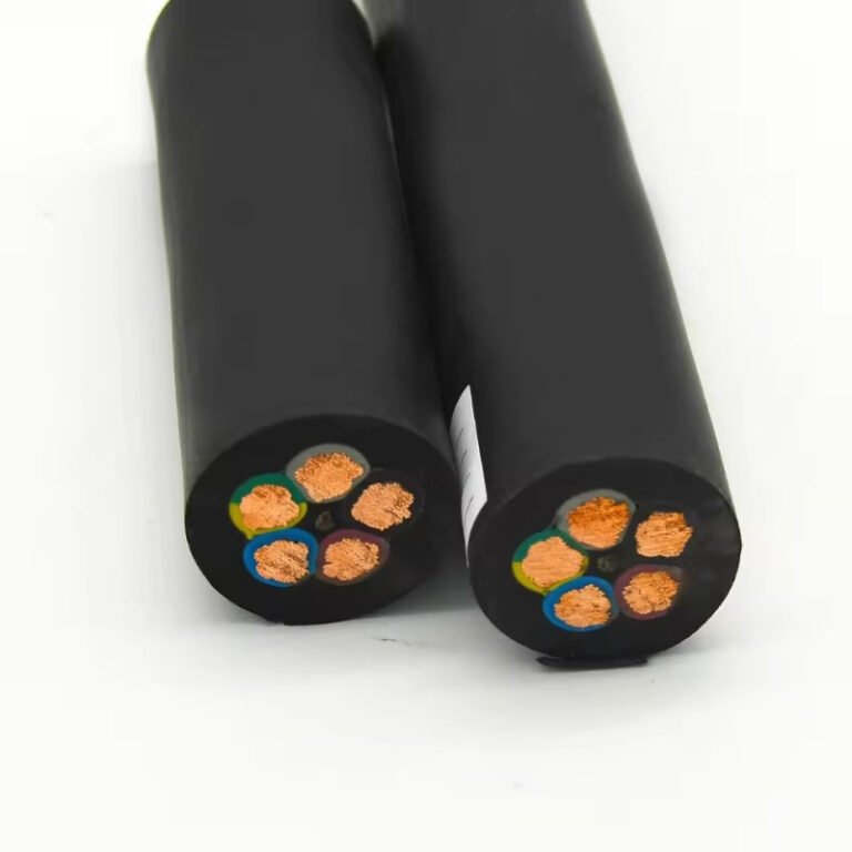
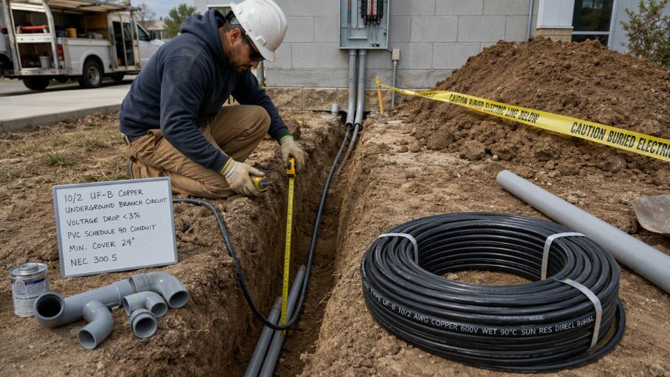
10/2 underground wire is not one universal product; it is a shorthand that usually means 10 AWG conductors, two insulated circuit conductors, and an equipment grounding conductor in a wiring method suitable for burial or wet underground raceway use. The words matter because a 10/2 cable that is correct for a 240 V pump may be wrong for a garage subpanel, and indoor cable does not become underground-rated just because someone hides it inside PVC.
“10 AWG” is the conductor size. For copper, 10 AWG has a DC resistance of roughly 1.0 ohm per 1,000 ft at 20°C, before allowing for temperature rise, connection resistance, and the fact that a circuit has an outgoing and return path. That resistance is why voltage drop becomes noticeable on long runs even when the breaker size is legal.
In North American residential and light commercial work, 10 AWG copper is commonly associated with 30 A branch circuits. That association is useful, but it is not the whole rule. Actual allowable ampacity depends on:
- The insulation temperature rating, such as 60°C, 75°C, or 90°C
- The wiring method, such as cable assembly versus individual conductors in conduit
- Terminal temperature ratings at breakers, disconnects, and equipment lugs
- Ambient temperature around the cable or conduit
- Number of current-carrying conductors grouped together
- Local code adoption and inspection practice
A plant maintenance electrician will usually look at the cable marking before trusting the breaker label. I have seen too many “30 amp” field assumptions fall apart once the jacket marking, conduit fill, or termination temperature rating was checked.
What “10/2 with ground” includes
A typical 10/2 with ground cable has:
- One insulated black conductor
- One insulated white conductor
- One bare or insulated equipment grounding conductor
The two insulated conductors are the circuit conductors. The grounding conductor is for fault clearing and bonding; it is not intended to carry normal load current and is not counted as a current-carrying conductor for ordinary load calculation.
That distinction causes a lot of buying mistakes. A 10/2 cable can serve a straight 240 V load using the two insulated conductors as the two hot legs, with the white conductor properly re-identified where required. It can also serve a 120 V load with one hot, one neutral, and ground. It cannot provide two hots, a neutral, and a ground at the same time. For that, you are in 10/3 with ground or a four-conductor feeder arrangement, depending on the installation.
UF-B, THWN-2 in conduit, USE-2, and URD are not interchangeable
The phrase “underground wire” gets used loosely at supply counters. The actual product family matters.
| Wiring method | What it is | Where it fits | Watch-outs |
|---|---|---|---|
| 10/2 UF-B cable | Factory cable assembly rated for underground feeder/branch-circuit use | Direct burial, often with conduit sleeves for physical protection where it rises from grade | Stiff to handle, unpleasant to pull through long conduit, must still meet burial depth and protection rules |
| 10 AWG THWN-2 conductors in PVC conduit | Individual wet-location conductors pulled through a listed raceway | Clean choice for underground conduit runs, especially where replacement may be needed later | Requires proper conduit fill, bends, pull boxes, fittings, and wet-location-rated conductors |
| USE-2 conductors | Underground service entrance conductors | Service-side underground work and certain exterior uses | Many USE-only conductors are not permitted to extend inside buildings except as allowed by code or when dual-rated |
| URD cable assemblies | Utility-style underground residential distribution cable | Common on utility distribution or service laterals | Not automatically approved for interior building wiring; markings and listing matter |
UF-B is convenient when the trench route is simple and direct. THWN-2 in conduit costs more in fittings and labor, but it gives better mechanical protection and future serviceability. The trade-off flips when the route has multiple bends, long pulls, or a high chance of later conductor replacement; then conduit with individual conductors is usually the cleaner maintenance decision.
Indoor NM-B cable is acceptable underground if it is installed inside PVC conduit.False
Underground raceways are treated as wet locations. The cable or conductors inside the conduit must be rated for wet locations, and indoor-only NM-B cable is not rated for that environment.
All underground raceways should be assumed wet. Condensation, groundwater migration, and seasonal temperature swings put moisture inside conduit even when the installer used purple primer neatly and tightened every adapter. Direct-buried cable lives in an even harsher environment, so the jacket and conductor insulation must be marked for that service.
Where 10/2 underground wiring is commonly used
10/2 underground wiring is useful where the load requirement matches two circuit conductors plus an equipment ground, with no need for both 120 V and 240 V loads from the same feeder.
Common fits include:
- Well pumps: Many small 240 V well pumps use two hots and ground, though the pump nameplate and control box wiring diagram decide the conductor count.
- Detached garage branch circuits: Suitable for a single branch circuit, not a full feeder with mixed loads unless the design is specifically limited.
- Outdoor receptacles: Often practical for a 120 V branch circuit when GFCI protection, burial depth, box rating, and in-use covers are handled correctly.
- Small outbuildings: Good for modest lighting and one defined load, but not for a future shop full of compressors, welders, and heaters.
- Irrigation controls: Often low load, but valve boxes, controllers, pumps, and GFCI requirements should be separated in the design.
- Landscape and site lighting circuits: Useful where load is known and voltage drop is checked over the full loop length.
- Straight 240 V equipment: Appropriate when the equipment does not require a neutral.
A representative mistake is running 10/2 to a shed because “it is only for lights,” then adding a freezer, battery charger, air compressor, and a small heater two winters later. The copper did not change, but the installation intent did. Retrofitting a larger feeder after concrete, landscaping, or asphalt is in place is always more expensive than sizing the raceway properly at the start.
Where 10/2 is the wrong choice
Do not treat 10/2 as a small feeder cable for every underground job. It is unsuitable for:
- Subpanels that require a neutral: A feeder panel normally needs two hots, an insulated neutral, and an equipment grounding conductor.
- Multiwire feeder applications needing additional conductors: Shared-neutral arrangements must be designed and protected correctly; 10/2 does not provide the required conductor set for many of these layouts.
- EV charging circuits above the conductor and cable rating: EV loads are continuous loads, and charger settings must match the circuit rating and code requirements.
- Installations expecting future expansion: If the owner is already talking about a second compressor, welder outlet, mini-split, or RV receptacle, 10/2 is usually a false economy.
- Any underground run using indoor-only cable: The burial method does not rescue the wrong insulation system.
The practical boundary is simple: 10/2 works when the load, voltage, grounding method, wet-location rating, burial method, and future capacity are all aligned. If the installation needs a neutral and two hots, or if the owner may later treat the run as a feeder rather than a branch circuit, select the conductor count and raceway plan before buying cable.
Voltage drop distance limits
For 10 AWG copper underground cable, the practical 3% voltage-drop planning range is roughly 60 ft at 120 V on a 30 A load, or about 120 ft at 240 V on the same load. At lighter loads the run can be longer, but the load current, not the breaker handle, is what drives the voltage drop calculation.
Voltage drop is simply the voltage used up pushing current through the resistance of the conductors. The equipment at the far end does not receive panel voltage; it receives panel voltage minus the loss in the hot and return path. On a 120 V circuit, that return path is the neutral. On a straight 240 V load using 10/2 with ground, it is the other hot conductor. The equipment grounding conductor is not part of the normal voltage-drop path.
The plain-English calculation is:
voltage drop increases when amperage or distance increases, and decreases when the wire gets larger or the circuit voltage gets higher.
For a single-phase branch circuit, the working estimate is:
Voltage drop = 2 × one-way distance × load current × conductor resistance per foot
That “2” matters. If the shed, pump, gate motor, or well control box is 80 ft from the panel, the circuit path is about 160 ft through copper because current has to go out and come back. In the field, I always check that everyone is talking about one-way trench length, not total conductor length. That one misunderstanding can make a good-looking estimate wrong by a factor of two.
For 10 AWG copper, a common planning resistance is about 1.0 ohm per 1,000 ft at 20°C. That is a useful clean-number basis for early layout work, but buried cable does not always operate at 20°C. Conductor resistance rises as copper gets hotter, so a circuit running near full load in warm soil, packed conduit, or a sun-heated riser may see more drop than the first calculation suggests. Depending on operating temperature, using the cold copper value can make the run look roughly 10-20% more generous than it will be under load.
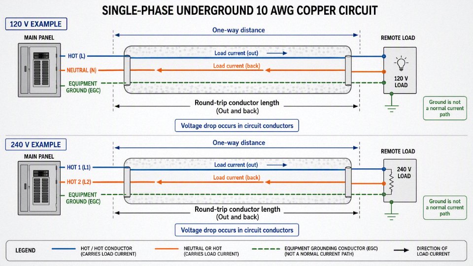
The table below uses 10 AWG copper, one-way distance, single-phase load, and a 3% voltage-drop target. Treat these as planning estimates, not permit drawings or a substitute for the local electrical code, the cable listing, or an engineer’s final calculation.
| Actual load current | Approx. max one-way run at 120 V for 3% drop | Approx. max one-way run at 240 V for 3% drop | Practical reading |
|---|---|---|---|
| 15 A | about 120 ft | about 240 ft | Often reasonable for modest lighting, controls, small tools, or light intermittent loads if starting current is not severe. |
| 20 A | about 90 ft | about 180 ft | A common planning point for receptacle-type loads, small equipment, and circuits not loaded to the full 30 A rating. |
| 24 A continuous load | about 75 ft | about 150 ft | Useful check for a 30 A circuit carrying an 80% continuous load. Heat and duty cycle start to matter. |
| 30 A | about 60 ft | about 120 ft | The upper-load case for a 30 A protected 10 AWG copper circuit; long runs often need upsizing. |
The reason 240 V can usually run about twice as far as 120 V at the same amperage is not that the copper loses fewer volts; it is that the same lost volts are a smaller percentage of a higher supply voltage. If a given 10 AWG run loses 3.6 V at 30 A, that is 3% of 120 V. The same 3.6 V is only 1.5% of 240 V, so the run can be extended until the loss reaches about 7.2 V, which is 3% of 240 V.
At the same amperage, same conductor size, and same percentage voltage-drop target, a 240 V circuit can usually run about twice as far as a 120 V circuit.True
The conductor resistance and current create roughly the same voltage loss per foot, but the allowable voltage loss doubles when the reference voltage doubles from 120 V to 240 V.
There is a trade-off hidden in that advantage. A 240 V branch circuit can be excellent for a pump, heater, compressor, welder supply, or dedicated machine because it reduces percentage voltage drop for a given power transfer. But a 10/2 cable used for a 240 V load normally does not provide a neutral for 120 V loads at the far end. If the outbuilding or equipment pad needs both 120 V receptacles and 240 V equipment, the wiring method may need a different conductor set, not just a longer piece of 10/2.
The common 3% number is a design recommendation for branch-circuit voltage drop, not a magic pass-or-fail line that applies the same way to every installation. Many electricians and engineers also use 5% as a total feeder-plus-branch-circuit design target. That means if a feeder to a subpanel already drops 2%, the branch circuit leaving that subpanel has less room left if you are trying to keep total drop near 5%.
Code enforcement usually focuses first on conductor ampacity, overcurrent protection, burial method, insulation type, physical protection, grounding, bonding, and installation workmanship. Voltage drop is still a serious design issue, but it is often treated as a performance recommendation unless a specific equipment standard, project specification, or local rule makes it mandatory. For production equipment, irrigation pumps, refrigeration, or anything with nuisance-trip history, I would not hide behind minimum code. Low voltage at the load becomes downtime, heat, weak torque, and callbacks.
A 30 A breaker does not mean the circuit always draws 30 A. A small pump may run at 11 A, a heater may draw 22 A, and a compressor may pull different current depending on pressure and supply voltage. Voltage drop follows actual current, so an 80 ft run that looks poor at 30 A might be fine for a steady 15 A load.
The breaker still matters because it sets the protective limit for the conductor and the circuit. You cannot justify a small conductor by saying the load “usually” draws less if the breaker and wiring method are not matched legally and safely. In plant terms, this is the same distinction as motor nameplate current versus overload protection: performance calculation and protection calculation talk to each other, but they are not the same calculation.
Motors are where the clean voltage-drop table starts to get a little optimistic. Pumps, compressors, refrigeration equipment, dust-collector motors, gate operators, and pressure washers may draw several times running current during startup. The inrush period is short, but the voltage sag can be enough to cause practical trouble:
- Motor hums or starts slowly, especially under load.
- Lights dim when the pump or compressor starts.
- Pressure switch chatters or contactor pulls in weakly.
- Breaker trips occasionally even though running current looks acceptable.
- Motor runs hotter because low voltage increases current for the same mechanical work.
- Control electronics reset during start, especially at the end of a long run.
The mechanism is straightforward. During startup, the motor has low back EMF, so current jumps. Higher current creates higher voltage drop in the buried conductors. Lower voltage at the motor reduces starting torque, which keeps the motor in the high-current starting condition longer. That longer acceleration time heats the winding and can push marginal installations into nuisance trips or shortened motor life.
This is why a run that works on paper at steady current can still be a poor installation. A 240 V, 20 A pump circuit at 170 ft might sit just inside a 3% steady-state estimate, but if the pump starts against head pressure at the end of a hot summer day, the starting sag may be the real design limit. In those cases, the next larger conductor is cheap compared with pulling failed cable out of a trench or explaining to operations why the same pump only trips in August.
Long underground runs often need upsizing to 8 AWG, 6 AWG, or larger even when 10 AWG copper is legally protected by the breaker. Upsizing does not allow you to ignore breaker and termination ratings, and it does not automatically change the ampacity of the circuit. It reduces resistance, which reduces voltage drop and heating in the conductors. The commercial trade-off is simple: larger cable costs more up front, but it can avoid equipment complaints, repeat service calls, and trench rework. Underground is the wrong place to save a few dollars per foot if the load is critical.
The 10 AWG copper estimates above stop holding when the conductor material, operating temperature, cable construction, power factor, installation environment, or load behavior changes enough to affect resistance or starting performance. For final selection, check the actual equipment running current, starting characteristics, supply voltage, one-way route length, conductor temperature rating, termination temperature limits, and local inspection requirements before committing to the trench.
Ampacity and breaker rules
Ampacity is the safety limit; voltage drop is the performance limit. A 10/2 underground run may be short enough for acceptable voltage drop and still be wrong if the conductor, terminals, load type, or installation conditions do not allow the breaker size you planned. For ordinary copper 10 AWG branch circuits, 30 A is the common ceiling, not a permission to ignore the rest of the circuit design.
Ampacity means the maximum current a conductor can carry continuously under stated conditions without exceeding its insulation temperature rating or creating unsafe heating at terminations and enclosures. Voltage drop is different. Voltage drop is about how much voltage is lost along the run before it reaches the load; excessive drop can make a pump start poorly, dim lights, waste energy, or shorten equipment life, but it is not the same question as whether the conductor is protected from overheating.
That distinction matters because people sometimes try to solve a long run by installing a larger breaker. That is backwards. A breaker protects the conductor and the installation, not the load voltage. Never increase the breaker size on 10 AWG conductors just to “push voltage farther”; use larger conductors, reduce the load, raise the supply voltage where appropriate, or redesign the circuit.
The common 10 AWG copper baseline
In typical residential and light commercial work, 10 AWG copper is commonly associated with 30 A branch circuits. That is the number most electricians, inspectors, and maintenance people will expect to see for a standard 10/2 copper cable serving a dryer-type load, small feeder-like branch, pump circuit, heater, or outdoor equipment branch circuit.
That common baseline still has conditions behind it:
- Conductor material: copper and aluminum are not interchangeable at the same AWG size. Aluminum has higher resistance, larger termination concerns, and different ampacity values.
- Insulation type: UF cable, THHN/THWN conductors in conduit, USE conductors, and other constructions are not treated identically.
- Terminal temperature rating: the lug, breaker, receptacle, disconnect, and equipment terminals can limit the usable ampacity.
- Ambient temperature: conductors installed in hot locations carry less current safely.
- Raceway fill and bundling: heat leaves a single cable more easily than it leaves a packed conduit or a bundle tied tight above a panel.
- Installation environment: rooftop exposure, thermal insulation contact, wet locations, and underground raceways can all change the design checks.
For many small branch circuits, the practical governing limit is not the highest temperature printed on the insulation. A THHN/THWN conductor may have a 90 °C insulation rating, but the breaker or device terminals may be rated for 60 °C or 75 °C use depending on equipment size and listing. In plain terms, you may be allowed to use the 90 °C ampacity column for adjustment and correction calculations, but the final protected ampacity often cannot exceed the terminal temperature limit. This is one of those details that looks academic until an inspector red-tags a job or a lug runs hot under load.
Continuous loads change the usable current
A 30 A circuit is not normally planned for 30 A of continuous load. Loads expected to run for three hours or more are typically sized at 125% of the continuous current, unless the equipment and overcurrent devices are specifically rated for a different arrangement. In everyday planning language, a standard 30 A circuit is commonly treated as suitable for about 24 A continuous load.
Examples where this shows up:
- Electric heating loads that cycle less than expected in cold weather.
- Process heaters or trace heating running through a shift.
- Ventilation fans, blowers, and circulation pumps that operate nearly all day.
- Battery chargers or power supplies with long-duration current draw.
- Agricultural or outdoor equipment that runs through hot afternoons when conductor temperatures are already elevated.
The mechanism is simple but unforgiving: current produces heat in the conductor and at terminations, and heat accumulation depends on both current magnitude and time. A short inrush or brief tool load is not the same thermal condition as a steady 28 A load buried in conduit for hours. In practice, this is why a circuit that “never trips” can still be poorly designed; breakers are not precision temperature monitors for every splice, lug, and cable segment along the run.
A 30 A breaker on 10 AWG copper usually means the circuit can supply 30 A continuously for any length of time.False
Standard continuous-load sizing normally limits a 30 A circuit to about 24 A of continuous load unless the equipment and overcurrent device are specifically rated and installed for higher continuous operation.
Breaker matching and small-conductor protection
For ordinary branch circuits, the breaker must be matched to the conductor ampacity and the equipment served. A 10 AWG copper cable on a 30 A breaker is common. A 10 AWG copper cable on a 40 A or 50 A breaker is not made acceptable by saying the run is long, the voltage drops too much, or the load “only pulls that much during startup.”
There are special rules in electrical codes, and they matter, but they are not a field shortcut. Motor circuits are the main case people run into. A well pump, lift pump, compressor, or similar motor may have:
- Branch-circuit conductors sized from motor full-load current tables or nameplate data.
- A breaker or fuse sized high enough to allow starting current.
- Separate overload protection intended to protect the motor from sustained overload.
- Manufacturer requirements for maximum breaker size, minimum conductor size, and disconnecting means.
That does not mean “motors can use any oversized breaker.” It means motor circuits are engineered differently. For a pump at the end of a long underground run, you need the motor horsepower, voltage, phase, full-load current, locked-rotor or starting characteristics where available, controller type, distance, and installation method. Guessing from cable size alone is how pumps get nuisance trips in spring startup, or worse, how conductors get under-protected.
Derating conditions that reduce usable ampacity
A single 10/2 underground cable feeding one normal branch circuit is often straightforward. The calculation changes when heat cannot escape as assumed by the base ampacity table.
Check these derating triggers before treating 10 AWG copper as a simple 30 A answer:
- Multiple current-carrying conductors in one raceway: several branch circuits sharing the same conduit can require adjustment. Equipment grounding conductors usually do not count, but neutrals may count depending on the circuit arrangement.
- High ambient temperature: hot mechanical rooms, sun-exposed exterior raceways, attic sections before the underground transition, and rooftop runs can force ampacity correction.
- Rooftop exposure: raceways above roofs can see temperatures well above normal outdoor air temperature, especially over dark membranes.
- Bundled cables: cables tied together for long distances above a panel or through framing do not cool like separated cables.
- Thermal insulation contact: cable buried in building insulation, foam, or other low-thermal-transfer material may retain heat.
- Wet-location and underground suitability: underground raceways are normally treated as wet locations, so conductor insulation and cable type must be suitable for that environment.
The trade-off is usually between installation convenience and electrical margin. Pulling several circuits through one larger conduit can look tidy and save trench work, but derating may push you into larger conductors or separate raceways. Running individual conduits or upsizing wire costs more up front, but it can avoid nuisance voltage complaints, inspection problems, and overheated terminations later.
Copper versus aluminum on 10/2 underground runs
Most small 10/2 underground branch-circuit cable discussions assume copper. Aluminum conductors at this size are uncommon for ordinary 10/2 branch-circuit cable, and substituting aluminum into a copper voltage-drop or ampacity estimate is not a harmless material swap. At the same AWG size, aluminum has higher resistance, so voltage drop increases and ampacity rules differ.
If aluminum is being considered for cost reasons, redesign the circuit from the beginning:
- Select the conductor size using aluminum ampacity and voltage-drop calculations.
- Confirm terminals are listed for aluminum conductors.
- Use the correct antioxidant compound if required by the termination manufacturer.
- Follow torque specifications with a calibrated driver, not wrist feel.
- Verify local code acceptance and inspection expectations.
The safe working assumption is narrow: 10/2 copper may commonly be protected at 30 A when the cable type, terminations, load profile, and installation conditions support it. Once the load is continuous, the raceway is crowded, the location is hot, the run serves a motor, or the conductor material changes, that simple 30 A association stops being enough and the circuit needs a code-based ampacity check, not just a voltage-drop calculation.
Burial method and cable choice
The safest underground run is usually not the one with the smallest trench; it is the one whose cable type, raceway, burial depth, protection, and inspection plan match the site. For a 10/2 branch circuit, direct-buried UF cable may be acceptable in simple residential work, while conduit or industrial raceway becomes the better choice where damage, serviceability, or future excavation is a concern.
Choosing the underground wiring method
| Method | Where it fits well | Main advantages | Watch-outs |
|---|---|---|---|
| Direct-buried UF cable | Short residential branch circuits, yard equipment, sheds where local code allows | Lower material cost, no full-length conduit required, simple trench layout | Harder to replace, vulnerable if route is forgotten, must be marked for direct burial |
| Individual wet-location conductors in PVC conduit | Common residential and light commercial underground runs | Easier pulling than cable assemblies, replaceable conductors, corrosion-resistant conduit | Needs correct conductor insulation rating for wet locations, proper glue joints, expansion planning |
| Rigid metal conduit | Shallow burial zones, exposed risers, high-damage areas | Strong mechanical protection, may be allowed at reduced cover where code permits | Higher labor cost, corrosion protection, bonding continuity must be right |
| Intermediate metal conduit | Similar to rigid metal conduit but often lighter | Good protection with less weight than rigid conduit | Local availability, corrosion, threading quality, bonding |
| Duct bank or industrial raceway | Plants, campuses, equipment yards, multiple feeders or future circuits | Organized routing, spare capacity, better maintainability | Engineering required for fill, heat, separation, pulling tension, drainage, and records |
UF cable is a cable assembly, so it carries its conductors and jacket as one relatively stiff package. That sounds convenient until someone tries to pull it through 80 feet of PVC with two 90-degree bends and a slightly oval trench section that got backfilled too soon. In practice, individual wet-location-rated conductors in conduit pull cleaner, especially with long sweeps, pulling lubricant, and enough raceway size to avoid fighting the job for half a day.
Do not assume “underground” means the same installation rule for every wiring method. Direct-buried UF cable, PVC conduit, rigid metal conduit, and industrial raceway can have different cover requirements, protection rules, and inspection expectations.
Typical burial depth benchmarks include about 24 in for direct-buried UF cable, about 18 in for residential branch circuits in PVC conduit, and about 6 in for rigid metal conduit, subject to local code and inspection.True
These are common benchmark values used for planning, but the installed depth must be verified against the adopted electrical code, local amendments, utility separation rules, and the authority having jurisdiction.
Burial depth, cover, and inspection authority
Depth is not just about hiding the cable. Soil cover protects against shovel strikes, vehicle loading, frost movement, erosion, and the slow damage caused by landscape work. A garden bed that looks harmless today may be aerated, edged, trenched for irrigation, or regraded three years from now by someone who never saw the original installation.
Plan burial depth around these checks:
- Adopted electrical code: National model codes are often modified locally, and the inspector enforces the adopted version, not a web article.
- Wiring method: Direct burial, PVC conduit, rigid metal conduit, and duct bank work can fall under different minimum cover rules.
- Circuit protection: Some residential branch circuits may have depth allowances tied to GFCI protection and circuit rating; verify before trenching.
- Utility separation: Maintain required spacing from gas, water, sewer, communications, and service laterals.
- Soil and site conditions: Rocky soil, flood-prone ground, expansive clay, and freeze-thaw conditions can justify more protection than the minimum.
- Inspection timing: Many jurisdictions want to see the trench, cable marking, conduit joints, and depth before backfill.
I have seen otherwise clean installations fail inspection because the trench was backfilled before the inspector saw the warning tape and conduit transition. That is an expensive way to learn that electrical work is partly an installation process and partly a documentation process.
Mechanical protection in the places that actually get damaged
Underground cable failures rarely happen in the neat middle of a straight trench. They happen at transitions, risers, building entries, and places where people later dig.
Pay special attention to:
- Where the wiring emerges from the ground: Use a suitable raceway sleeve or riser protection up to the required height. Weed trimmers, snow shovels, and mower decks are rougher on exposed cable than most drawings admit.
- Driveway and vehicle crossings: Consider deeper cover, stronger conduit, sleeving, or an engineered crossing. Soil compaction and tire loading can deform light-duty raceway if the trench bedding is poor.
- Building entries: Seal and support the transition properly. Water following a raceway into a wall or panel is a common nuisance and sometimes a serious corrosion problem.
- Landscaping zones: Avoid tree root areas, future fence lines, irrigation routes, and edging strips where possible.
- Future excavation risk: If the area may later receive signs, bollards, lighting poles, drainage work, or machinery pads, route the cable where it can be found and protected.
Conduit sizing, pulling, bends, and heat
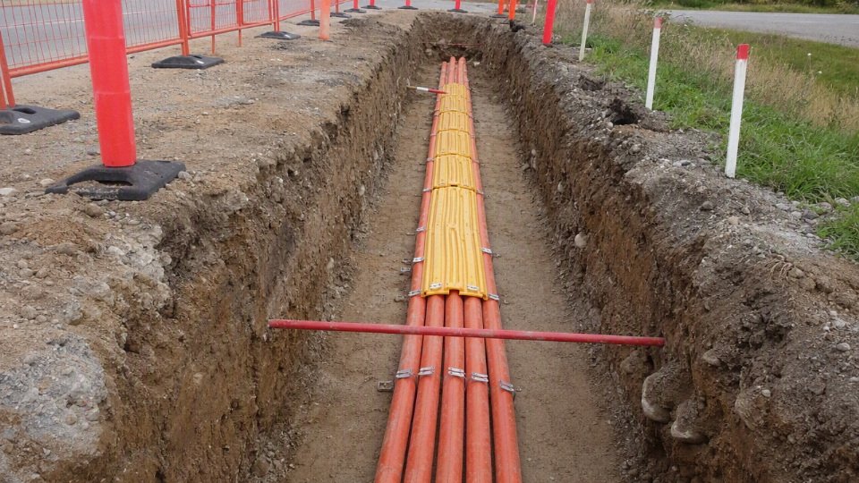
Raceway selection is where the low-bid installation often starts to age badly. A conduit that is technically large enough by fill calculation may still be a poor choice if the pull has long distance, multiple bends, cold-weather stiffness, or no practical pull point.
For a 10/2 underground circuit, check:
- Conduit fill: Follow the applicable fill rules for the actual conductor or cable outside diameter. Cable assemblies take more space and pull worse than individual conductors.
- Pulling difficulty: Long pulls need generous raceway size, long sweep bends, and sometimes intermediate pull boxes. Four tight quarter-bends in a small PVC run can turn a simple job into a tug-of-war.
- Heat dissipation: Conductors underground shed heat differently than conductors in open air. Raceway grouping, duct banks, soil thermal conditions, and conductor count can require derating.
- Expansion and movement: PVC expands and contracts with temperature. Long outdoor runs need expansion fittings where movement can stress joints or enclosures.
- Bend quality: Use long sweeps where practical. Sharp bends increase pulling tension and can damage insulation, especially when someone gets impatient with the fish tape and a pickup truck.
- Drainage reality: Outdoor underground conduit is treated as a wet location because water gets in through condensation, joints, and breathing cycles. Use conductors rated accordingly.
The trade-off is straightforward: direct burial is simpler and cheaper up front, while conduit costs more but gives better mechanical protection and future replacement options. The choice flips toward conduit when the run crosses hardscape, serves important equipment, may need future conductors, or sits in a plant area where excavation and maintenance activity are normal.
Splices, junctions, grounding, and bonding
Underground splices are not the place for ordinary wirenuts and hope. Any splice or termination exposed to underground moisture must be listed for direct burial or wet locations, and it must be installed exactly as the kit instructions require. Gel-filled, resin, heat-shrink, or molded splice systems can work when properly selected, but the wrong kit on the wrong cable jacket can let water migrate along the conductor strands.
Use these rules of thumb:
- Avoid underground splices when a continuous pull is practical.
- If a splice is necessary, use a listed underground or wet-location splice system.
- Place junction boxes where they remain accessible if the code requires access.
- Protect splice locations from standing water, soil movement, and mechanical strain.
- Label the circuit so the next electrician knows what is buried there.
Grounding and bonding deserve the same discipline. The equipment grounding conductor must be continuous and correctly sized for the circuit. Metal raceways, metal boxes, pump housings, outdoor disconnects, and equipment enclosures must be bonded so a fault has a low-impedance path back to the source. For detached structures, panels, feeders, grounding electrodes, neutral isolation, and bonding jumpers need to be handled under the applicable code rules; this is not an area to improvise because “the light turns on.”
Route marking and documentation
The cheapest protection installed in an underground electrical job is often the one people skip: records. Warning tape placed above the cable, route mapping, durable panel labeling, and as-built notes prevent future damage. Where nonmetallic conduit or direct-buried cable may be hard to locate, a tracer wire or other locating method may be appropriate, especially on larger properties, farms, equipment yards, and industrial sites.
A usable as-built record should include:
- Circuit source and breaker identification
- Cable or conductor type and size
- Raceway type and approximate burial depth
- Route sketch with fixed references, not just “across the yard”
- Splice and junction locations
- Photos before backfill
- Inspection date or permit reference where applicable
Pre-installation verification checklist
Before trenching or ordering material, verify the following:
- Cable marking
- Confirm the cable is marked for the intended underground use.
- Do not assume indoor NM cable can be buried because it fits in conduit.
- Wet-location rating
- Confirm individual conductors in underground conduit are rated for wet locations.
- Check supplier documentation, not just jacket color.
- Conductor count
- Confirm whether the circuit needs two insulated conductors plus an equipment grounding conductor, or a different conductor arrangement for the equipment being served.
- Burial depth
- Confirm required cover for the wiring method.
- Coordinate with the inspector before backfill.
- GFCI requirements
- Check whether the circuit, outlet type, equipment, location, or burial-depth allowance requires GFCI protection.
- Conduit transitions
- Plan risers, sleeves, expansion fittings, long sweeps, building entries, and physical protection at exposed points.
- Splices and junctions
- Avoid buried splices where possible.
- If unavoidable, use listed direct-burial or wet-location splice products and document their location.
- Grounding and bonding
- Verify equipment grounding conductor continuity.
- Bond metal raceways, boxes, and equipment enclosures as required.
- Inspection steps
- Confirm permit needs.
- Schedule trench inspection before backfill.
- Keep photos and material labels for closeout records.
For procurement, this means the bill of materials should not stop at “10/2 underground wire.” It should specify the cable or conductor rating, raceway type, fittings, splice system if needed, warning tape, grounding components, and documentation requirements so the installation can pass inspection and still be serviceable years later.
Load examples and distances
Use the distances below as planning examples, not permit drawings. They assume 10 AWG copper conductors, a rough 3% voltage-drop target, and the load current shown in the row rather than the breaker handle size. Soil temperature, conduit fill, cable type, terminations, local inspection practice, and equipment voltage tolerance can move the final answer.
| Application | Voltage | Typical load current to check | Neutral needed? | Rough distance range on 10 AWG copper | When to upsize or redesign |
|---|---|---|---|---|---|
| Outdoor receptacle circuit to a shed | 120 V | 12–20 A, sometimes near 20 A with tools | Yes | About 90 ft at 20 A; farther if the actual load is lower | Heavy saws, compressors, heaters, or runs much beyond moderate backyard distance |
| Well pump or irrigation pump | 240 V | Often 8–25 A running, higher during start | Usually no for straight 240 V motor | About 120 ft at 30 A; about 180 ft at 20 A | Long pump leads, hard starting, low utility voltage, or tight manufacturer voltage limits |
| Detached garage branch circuit | 120 V or 240 V | Highly variable; often grows over time | Depends on loads; subpanel usually needs more than 10/2 | 10/2 may suit one limited circuit, not a general garage feeder | Door openers, chargers, compressors, welders, heaters, future subpanel plans |
| Landscape lighting or controls | Often low voltage after transformer; line side may be 120 V | Low current on controls, higher on lighting secondary | Depends on system | Line-side distance may be easy; low-voltage secondary can be the problem | Long 12 V or 24 V runs, many fixtures at the far end, poor transformer placement |
| Small 240 V heater or equipment load | 240 V | 15–24 A continuous or noncontinuous depending on equipment | No, if no 120 V components | About 180 ft at 20 A; about 120 ft at 30 A | Continuous loads above usable circuit capacity, voltage-sensitive controls, future equipment changes |
For the same current and voltage-drop percentage, a 240 V load can usually be run about twice as far as a 120 V load on the same 10 AWG copper conductors.True
The conductor loses roughly the same number of volts at the same current, but 3% of 240 V is twice the allowable voltage loss of 3% of 120 V. The final distance still depends on actual load current, conductor material, installation temperature, and the equipment voltage tolerance.
120 V, 20 A outdoor receptacle circuit to a shed
A 120 V shed receptacle circuit is the classic case where 10/2 underground cable can be useful even though the breaker may only be 20 A. At roughly 20 A load, 10 AWG copper is in the neighborhood of 90 ft for a 3% drop target; at lower working loads, the distance stretches in proportion to the lower current.
That does not mean every shed should get 10/2 and be forgotten. A battery charger, a few LED lights, and a small fan are easy service. A miter saw starting under load, a pancake compressor cycling on a cold morning, or a portable space heater left plugged in all move the circuit closer to its worst case. Voltage drop is not just a dim-light issue; lower voltage increases motor current for some equipment, makes startup weaker, and can make nuisance trips look like a breaker problem when the real problem is the long underground run.
For a simple backyard shed, I would normally compare three numbers before buying cable:
- The one-way trench distance, including the rise up each wall and route through fittings.
- The largest likely simultaneous load, not just the receptacle rating.
- Whether the shed might later become a workshop rather than a storage building with one outlet.
If the real load is 10 A instead of 20 A, the same voltage-drop math gives roughly double the distance. The trap is that receptacles are open-ended; the next owner, tenant, or maintenance guy may plug in a heater or compressor because the receptacle accepts it.
240 V well pump or irrigation pump
A 240 V pump is where 10/2 often reaches farther than people expect, because there is no neutral load and the voltage-drop percentage is based on 240 V. A 20 A running load on 10 AWG copper may be around the 180 ft class for a 3% target, while a 30 A load is closer to 120 ft before installation derating and equipment-specific limits are checked.
Motor starting is the part that deserves respect. A pump motor can draw several times its running current for a short period, and the voltage dip during that moment is what decides whether the motor comes up cleanly or grunts, overheats, and abuses the pressure switch or contactor. On an irrigation system, the worst condition may not be the brochure running amps; it may be low incoming utility voltage at the end of a rural service, hot conductors in conduit, and a pump starting against pressure because a check valve is holding the column.
For pumps, do not size from distance tables alone. Check:
- Motor nameplate voltage and full-load current.
- Manufacturer maximum circuit length or minimum conductor size, if supplied.
- Starting method: direct-on-line, soft starter, VFD, pressure switch, or controller.
- Distance from panel to controller and controller to pump, including well drop cable where applicable.
- Whether controls, heaters, or receptacles need a neutral.
A plain 240 V pump can use two insulated conductors plus equipment grounding conductor, so 10/2 with ground may match the circuit layout. If the pump control box or equipment also needs 120 V, that changes the conductor requirement; 10/2 cannot magically provide two hots, a neutral, and ground.
Detached garage circuit
A detached garage is where 10/2 is often undersold at first and regretted later. It may be enough for one defined branch circuit, but it is usually a poor choice if the owner expects lights, receptacles, door openers, battery charging, a compressor, freezer, welder, EV charger, or a future subpanel.
The commercial problem is not the price difference between wire sizes on bid day. It is the trench. Once the driveway edge is cut, the PVC is glued, and the landscaping is put back, saving a small amount on copper can lock the building into a circuit that no longer fits the use. I have seen plenty of plants and farm shops where someone did the “just enough for now” underground feed, then spent years managing loads with handwritten notes on the panel door. That is not engineering; it is inconvenience made permanent.
For a garage, separate the decision into these categories:
- Single 120 V branch circuit: 10/2 may be reasonable for lights and convenience receptacles if distance and load are modest.
- Single 240 V equipment circuit: 10/2 may fit one compressor, heater, or machine if no neutral is required.
- Mixed 120 V and 240 V use: 10/2 is usually the wrong cable arrangement because neutral demand appears.
- Subpanel expectation: plan feeder conductors, grounding and bonding, disconnecting means, and local code requirements from the start.
Oversizing wire for voltage drop on a long underground run is not wasteful if it avoids weak motor starting, warm conductors, nuisance complaints, and retrenching later. The preferred choice flips only when the load is fixed, the distance is short, the installation is accessible, and future use is genuinely limited.
Landscape lighting and controls
Landscape lighting fools people because the load may be small, yet voltage drop can still dominate the design. The 120 V feed to a transformer might be perfectly acceptable on 10/2 over a fair distance, while the 12 V or 24 V lighting circuit after the transformer struggles badly because a one- or two-volt loss is a large percentage of the available voltage.
In practice, transformer location can matter more than the underground branch-circuit gauge. Put the transformer at the house and run long low-voltage cables to the far tree line, and the last fixtures may look weak or uneven. Move the transformer closer to the load, feed it with a properly protected 120 V circuit, and the secondary cable lengths become easier to manage.
Controls are different again. A gate control, irrigation controller, relay panel, sensor circuit, or signal input may draw very little current, so voltage drop on 10 AWG is rarely the limiting issue. The more important checks are often wet-location ratings, surge exposure, rodent damage, spare conductors, and whether low-voltage and power wiring are being separated as required by the equipment instructions and applicable code.
Small 240 V heater or equipment without neutral
A small 240 V heater, kiln accessory, pump, air compressor, or fixed machine can be a good fit for 10/2 if the equipment needs only two hots and a grounding conductor. At 240 V, the distance allowance is kinder than at 120 V, but the load type matters: a continuous heater load is not treated the same way as a motor that cycles.
For continuous loads, many code frameworks require the circuit to be sized at 125% of the continuous current, subject to the exact rule set and equipment listing. That means a load that appears to be “under 30 A” may still be too large for a 30 A circuit if it runs for the defined continuous period. A 240 V heater around 20–24 A may be plausible on a properly designed 30 A circuit, while a larger heater that sits right at 30 A is not something to wave through without checking the code calculation, terminal temperature ratings, and manufacturer instructions.
Adjusting the example distances is straightforward for planning: voltage drop is roughly proportional to current. If the table distance is based on 20 A and your confirmed load is 10 A, the same conductor can go roughly twice as far for the same percentage drop. If the load is 25 A, reduce the 20 A distance by about 20%. This is an estimate, not a substitute for the actual conductor resistance, circuit length, temperature adjustment, and permitted installation method.
The boundary is simple: these examples hold for copper 10 AWG underground branch-circuit planning with ordinary voltage-drop targets. They do not settle aluminum sizing, special motor circuits, hazardous locations, marina or agricultural rules, utility service conductors, or equipment with a tighter voltage window than the usual field assumption.
When to upsize wire
Upsize from 10/2 underground wire when the circuit is long, heavily loaded, motor-driven, likely to be expanded, or required to serve both 120 V and 240 V loads. A small saving on cable can disappear quickly if the installed circuit gives weak starting torque, nuisance trips, rejected inspection, or forces a second trench later.
The first trigger is voltage drop under the actual operating load, not the breaker size printed on the panel schedule. If a 10 AWG copper underground run is feeding a 30 A load near its limit, the practical 3% voltage-drop distance is much shorter at 120 V than at 240 V. That happens because the same conductor resistance causes the same voltage loss in volts, but those lost volts represent a larger percentage of a 120 V circuit. A 120 V pump controller, gate operator, heater, or small compressor at the end of a long run may still “work,” yet run hotter, start slower, or throw intermittent faults that are hard to diagnose after the trench is closed.
Motor loads deserve special caution. Pumps, compressors, refrigeration equipment, HVAC condensers, welders, and some shop tools do not behave like a steady resistive heater. At start-up, current can jump several times above running current for a short period. The wire does not instantly overheat from that short surge, but voltage at the equipment terminals can sag right when the motor needs torque. In practice, that means a well pump that starts fine in spring may struggle during a low-voltage summer afternoon when the utility feed is already soft and the conduit is warm.
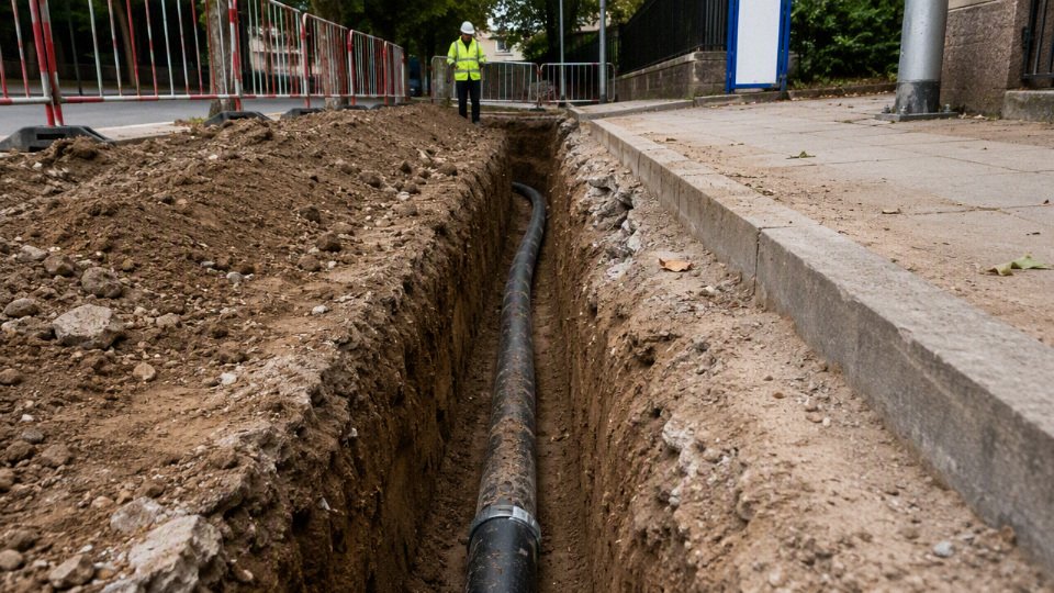
A useful way to look at the decision is this: 10/2 may be electrically safe on ampacity and still be a poor design choice on performance. Code compliance, voltage drop, equipment warranty conditions, and future use are related, but they are not the same test.
| Project condition or symptom | Recommended design response |
|---|---|
| Calculated voltage drop exceeds the design target at the real load current | Upsize conductors, shorten the route, raise circuit voltage where equipment allows, or split the load |
| Long 120 V run carrying a near-continuous 20 A to 30 A load | Consider moving from 10/2 to 8/2 or redesigning the circuit at 240 V if the load is compatible |
| Pump, compressor, HVAC, refrigeration, welder, or motor load at the far end | Check starting current and minimum equipment voltage; upsize conductors if start voltage is marginal |
| Detached structure may later need lights, receptacles, tools, charger, freezer, or controls | Plan a feeder rather than a bare-minimum branch circuit; retrenching usually costs more than copper or aluminum saved |
| Need both 120 V and 240 V at the destination | 10/2 is the wrong conductor arrangement; use the proper neutral and grounding configuration, often 10/3 or a four-wire feeder depending on the design |
| Subpanel is planned in a garage, shed, pump house, or outbuilding | Use a feeder with the required ungrounded conductors, insulated neutral, and equipment grounding conductor; verify grounding and bonding rules locally |
| Smart controls, timers, sensors, or GFCI devices need a neutral | Do not assume a two-conductor cable will support the control scheme; confirm the wiring diagram before buying cable |
| Multiple current-carrying conductors in one raceway or long duct bank | Apply derating and temperature correction; upsizing may be needed even before voltage drop is considered |
| High ambient soil or conduit temperature, rooftop transition, or sun-exposed riser | Check insulation temperature rating, termination rating, and correction factors; heat raises conductor resistance and reduces usable ampacity margin |
| Equipment trips, dims lights, faults on undervoltage, or starts inconsistently | Measure voltage at the load during starting and running, not just open-circuit voltage at the panel |
| Downtime or service call cost is high | Favor the larger conductor or feeder design; the installed cost difference is often small compared with one failed production shift or spoiled product load |
The common upgrade paths are not interchangeable. Moving from 10/2 to 8/2 is usually a same-function upgrade: two current-carrying conductors plus ground, better suited to a longer run at the same load because lower resistance cuts voltage drop. Moving from 10/2 to 10/3 is different; it adds a neutral for circuits that need both line-to-line and line-to-neutral voltage, but it does not reduce voltage drop the way a larger conductor does. For detached buildings, the practical step is often from a simple two-conductor branch circuit to a properly sized four-wire feeder supplying a subpanel. That gives room for load management, separate breakers, and future circuits, but it also brings grounding, bonding, disconnect, and inspection requirements that must be designed rather than improvised.
Derating is where many “cheap” underground installations get less cheap. Conductors in a warm conduit run together heat each other, and higher conductor temperature increases resistance. Higher resistance increases voltage drop, which can make motors draw current for longer during start-up, which adds more heating. It is not dramatic on a lightly loaded garden circuit; it matters on long duct runs, grouped feeders, pump stations, agricultural buildings, and industrial sites where conduits leave a panel room already carrying heat from adjacent circuits. The preferred choice can flip if the load is intermittent, the run is short, and expansion is impossible; in that case, upsizing may buy little beyond comfort margin.
For procurement, do not purchase “10/2 underground cable” as a loose description on a bulk order. Specify the conductor material, conductor size, number of insulated conductors and grounding conductor, insulation system, jacket or sheath rating, direct-burial or conduit suitability, applicable standard, voltage rating, temperature rating, printing and marking language, reel length, packaging method, and required factory test documents. For export or multi-site purchasing, confirm whether the project needs copper or aluminum conductors, metric or AWG identification, English jacket markings, third-party certification, and batch traceability. A reel that is electrically sound but marked to the wrong standard can still become a receiving, inspection, or customs problem.
The commercial trade-off is simple but easy to underweight during estimating: larger cable costs more, may need larger conduit, heavier reels, wider pulling planning, and different lugs or terminations. What it buys is lower voltage drop, cooler operation, better starting behavior, and more room for future load. Before committing to 10/2, price the next logical size and the correct conductor count against the cost of opening the trench again; that comparison usually tells the truth faster than arguing over the cheapest reel.
Specification and procurement checks
Start procurement with a written cable schedule, not a casual request for “10/2 underground wire.” At minimum, the purchase specification should lock down:
- Conductor size: 10 AWG, or the metric cross-section if the project is IEC-based.
- Conductor material: copper or aluminum, with no substitution unless engineering approves the voltage drop and termination changes.
- Conductor count: two insulated current-carrying conductors plus grounding conductor, if the circuit design requires equipment grounding.
- Grounding conductor: bare or insulated, correct size, and acceptable under the installation code.
- Voltage rating: matched to the system and authority requirements, commonly 600 V class in many North American branch-circuit products.
- Insulation and jacket type: suitable for wet locations, underground exposure, conduit pulling, or direct burial as applicable.
- Burial approval: direct-burial rating if it will be installed without raceway protection.
- Color coding: conductor colors aligned with the destination market and panel schedule.
- Standards and markings: printed, legible, continuous markings showing size, rating, type, manufacturer, and certification where required.
For underground cable, the marking on the jacket matters almost as much as the copper inside it. Inspectors, contractors, and maintenance crews will often judge acceptance from the printed type designation, voltage rating, conductor size, and listing mark before anyone cuts a sample. If those markings are wrong, incomplete, or in the wrong certification language for the market, a technically sound cable can still be rejected at site.
Buyers sourcing in volume should request factory test and inspection records with each production lot, not just a catalog sheet. Useful documentation normally includes:
- Conductor resistance test results, because high resistance points to undersized copper, poor stranding control, or wrong material.
- Insulation resistance test data, especially important for wet-location and buried service.
- Voltage withstand testing, to confirm insulation integrity before shipment.
- Dimensional checks for conductor diameter, insulation thickness, jacket thickness, and overall cable diameter.
- Marking verification, including print content, spacing, durability, and reel identification.
- Packaging inspection records, including reel condition, end sealing, wrapping, and export protection.
The mechanism is simple but expensive when missed: reduced conductor area raises circuit resistance, which increases voltage drop and heat at the same load; thin or uneven jackets reduce the margin against moisture ingress, abrasion during pulling, and soil-side damage over time. A cable that only “looks like 10/2” is not enough for buried work; the buyer needs test evidence that it electrically and mechanically matches the specification.
International procurement adds another layer. A North American-style 10/2 underground branch circuit may be specified around NEC practice, AWG sizes, equipment grounding rules, and local listing requirements. IEC-based projects may describe conductors by square millimeters, use different color conventions, require different cable constructions, and rely on local certification schemes. A cable accepted in one country can be refused in another because the approval mark, test standard, fire performance requirement, conductor color, or product designation does not match the authority having jurisdiction.
That is where early supplier review saves money. For a long underground run, the engineer may care about voltage drop and ampacity; the procurement team may care about minimum order quantity, reel length, packing size, lead time, and payment terms; the site inspector may care about certification marks and burial approval. All three have to be reflected in the same specification before production starts. The trade-off is familiar: a stock cable can ship faster and cost less per meter, but a project-specific cable with documented construction, markings, and test reports reduces the risk of customs delay, inspection failure, and field rework. The cheaper option stops being cheaper when crews are standing beside an open trench waiting for an approved replacement reel.
Quality risks worth controlling before shipment include:
- Undersized conductor cross-section or conductor resistance outside tolerance.
- Incorrect conductor material, especially copper-clad or aluminum substituted for copper without approval.
- Poor jacket thickness control, creating weak spots during pulling or direct burial.
- Moisture resistance that is not proven for wet locations or soil exposure.
- Illegible, incomplete, or non-compliant jacket markings.
- Inconsistent reel lengths that disrupt installation planning and waste estimating.
- Reel damage, loose winding, crushed flanges, or poorly sealed cable ends during export shipping.
For international project supply, manufacturer capability matters beyond the extrusion line. Jinda was established in 1987 and operates as a cable manufacturer with five production bases, 470,000 m² of manufacturing space, more than 1,000 employees, and customers in over 50 countries. That scale is relevant when a buyer needs repeated batches, customized specifications, coordinated documentation, and technical communication across engineering, purchasing, inspection, and after-sales teams. It does not remove the need for project approval, but it makes a structured approval process more practical than buying anonymous reels through a spot trader.
A planned buyer checklist should include:
- Applicable standard or code basis for the destination market.
- Conductor size, material, and stranding requirement.
- Number of insulated conductors and grounding conductor arrangement.
- Voltage rating and temperature rating.
- Insulation type, jacket type, and wet-location suitability.
- Direct-burial approval, if the cable will be installed without conduit.
- Required color coding and jacket printing language.
- Sample approval before bulk production, when the project schedule allows.
- Factory test report format and lot traceability.
- Third-party certification or local approval mark, if required by the authority or client.
- Lead time, production batch size, and spare-length allowance.
- Reel length tolerance, reel labeling, packing method, and cable-end sealing.
- After-sales technical support for documentation, installation questions, or claim handling.
The boundary is the local approval process: no supplier document should override the latest project specification, electrical code, utility requirement, or inspector decision. For a serious bulk buy, align the cable schedule, test documents, certification requirements, and reel plan before the purchase order is released.
Frequently asked questions
How far can I run 10/2 UF wire on a 30 A breaker?
For planning, 10 AWG copper carrying 30 A is usually kept to roughly 60 ft at 120 V or 120 ft at 240 V if you are trying to stay near a 3% voltage drop. Those are not code-approved maximums; they are voltage-drop benchmarks before project-specific derating, terminal temperature limits, soil conditions, conduit fill, and actual load profile are checked.
If the load is continuous, motor-driven, or sensitive to low voltage, do the calculation from the actual current, one-way circuit length, conductor material, and operating voltage. A 30 A breaker does not mean the circuit always draws 30 A, but sizing the run as if it might is usually the safer design assumption.
Can I run 10/2 underground for 100 ft?
Yes, in some cases. A 100 ft run of 10/2 copper can be reasonable for a 240 V load or a lower-current 120 V load, but it is usually too long for a full 30 A, 120 V circuit if you are trying to hold voltage drop near 3%.
The practical symptom is not just a number on paper. You may see slow motor starts, dimming lights, nuisance trips on equipment with undervoltage protection, or warmer-running tools. For a shed receptacle used lightly, it may be acceptable after calculation; for a 120 V compressor or heater pulling close to 30 A, I would look hard at 8 AWG.
Is 10/2 good for a 30 A circuit?
10 AWG copper is commonly associated with 30 A branch circuits, but the whole installation has to match that rating. Check the cable type, conductor material, insulation rating, terminal temperature rating, breaker type, and any derating from ambient temperature or conduit fill.
Do not treat “10/2” as a complete specification. Copper 10/2 UF-B, copper individual wet-rated conductors in conduit, and aluminum conductors are different purchasing and installation decisions. The breaker must protect the weakest approved part of the circuit, not the label that sounds most familiar.
Can 10/2 feed a subpanel?
Usually, no. Most subpanels need two hot conductors, one neutral, and one equipment grounding conductor, with neutral and ground isolated in the subpanel. Typical 10/2 with ground gives you two insulated conductors plus a ground, so it normally cannot provide a 120/240 V feeder with a separate neutral and grounding path.
A 240 V-only load without neutral is a different situation, but that is not what most people mean by a subpanel. For a workshop, detached garage, pump house with lights and receptacles, or mixed-load panel, expect to review a 4-wire feeder arrangement with the local inspector.
Does underground wire have to be in conduit?
Not always. Direct-burial UF cable is designed to be buried in soil without a continuous conduit system, provided burial depth, mechanical protection, and local code requirements are met. Conduit systems use conductors or cable approved for wet locations, and the raceway provides routing and physical protection.
The weak points are usually transitions:
- Where the cable leaves the ground
- Where it runs up a wall or post
- Where it enters a box, pedestal, pump housing, or building
- Where landscaping tools, vehicle traffic, frost heave, or rodents can damage it
Those areas often need conduit protection even when the horizontal run is direct buried.
What is the difference between 10/2 and 10/3 underground wire?
10/2 generally means two insulated 10 AWG conductors, usually with an equipment grounding conductor when sold as cable. 10/3 generally means three insulated 10 AWG conductors plus ground.
That extra insulated conductor matters. 10/2 can serve many 120 V circuits or straight 240 V loads that do not need a neutral. 10/3 is used where you need two hots and a neutral, such as many 120/240 V feeders, some appliances, and circuits where both voltage legs are required.
Can I use indoor cable in underground conduit?
No, not if the cable is only rated for dry indoor locations. Underground conduit is treated as a wet location because water enters through condensation, fittings, ground movement, and imperfect seals. I have opened plenty of “sealed” underground conduits that had standing water in the low spot.
Use conductors or cable marked for wet locations, such as suitable UF cable or individual conductors with the proper wet-location rating, depending on the wiring method. NM-B indoor cable is not made acceptable just because it is inside buried PVC.
Should I use 8 AWG instead of 10 AWG?
Use 8 AWG when the run is long, the load is close to the circuit rating, motor starting is a concern, or future expansion is likely. The larger conductor lowers resistance, so voltage drop decreases and starting performance improves.
The trade-off is higher cable cost, larger conduit or harder pulling in some layouts, bigger termination space, and more attention to compatible lugs. Still, trenching is usually the expensive, dirty part of the job. If the route crosses a driveway, finished landscape, or concrete apron, upsizing during the first installation is often cheaper than retrenching later.
Is voltage drop a code violation?
Voltage drop is commonly treated as a design recommendation rather than a simple pass/fail code rule for many branch circuits, but that does not mean it can be ignored. Equipment manufacturers, local authorities, project specifications, and good workmanship requirements may still expect the circuit to deliver usable voltage at the load.
For procurement, this is why cable length belongs in the inquiry. A buyer asking only for “10/2 UF cable” may receive a compliant product that still performs poorly on a long run.
Can I bury a splice in 10/2 underground wire?
Only use a splice method listed for underground or direct-burial service and rated for wet locations. Ordinary wire nuts, tape, indoor junction boxes, and casual heat-shrink repairs do not belong in soil.
Acceptable repairs usually involve a listed underground splice kit with sealed connectors, resin, gel, or heavy-wall adhesive-lined heat shrink, depending on the product. Even then, think about serviceability. If the splice is under a driveway or deep below a landscaped bed, the “cheap repair” may become the most expensive fault on the property later.
Verify your run and specification
Before you buy cable or trench the route, lock down the design inputs in writing. For 10/2 underground wire, the decision is not just “10 AWG equals 30 A.” You need the circuit voltage, actual running current, whether the load is continuous, one-way circuit length, copper or aluminum conductor material, burial method, and whether the load needs a neutral.
Use this field workflow:
- Confirm the load, not just the breaker size.
- Nameplate current is a start, but heaters, pumps, compressors, welders, and RV loads behave differently.
- Continuous loads may need sizing treatment above the running current, depending on the applicable code and equipment listing.
- Motors deserve extra caution because starting current and voltage dip can cause nuisance trips, contactor chatter, hot windings, or poor startup under load.
- Calculate voltage drop on the one-way distance.
- Use the actual conductor material, circuit voltage, and expected current.
- As a rough reference from the earlier calculations, 10 AWG copper at 30 A reaches about a 3% drop near 60 ft on 120 V and about 120 ft on 240 V, before site derating and installation effects.
- At 20 A, the same copper conductor may be closer to about 90 ft on 120 V and 180 ft on 240 V.
- Compare the result with the design target.
- Many designers use 3% as a branch-circuit voltage drop target, but the final requirement depends on the equipment, total feeder-plus-branch drop, and local practice.
- A light or receptacle circuit may tolerate a bit more drop than a motor, control transformer, EV charger, or sensitive outdoor equipment.
- Check ampacity, breaker rules, and conductor count.
- Confirm whether 10/2 is allowed on the intended overcurrent device.
- Confirm whether the load needs two hots only, hot-neutral, or two hots plus neutral.
- Subpanels usually need more than 10/2 because separate insulated conductors and grounding requirements apply.
- Confirm the burial method before specifying the cable.
- Direct-buried UF cable, PVC conduit, and rigid metal conduit are not interchangeable purchasing decisions.
- Typical burial benchmarks include 24 in for direct-buried UF cable, 18 in for residential branch circuits in PVC conduit, and 6 in for rigid metal conduit, subject to the current local code and inspection.
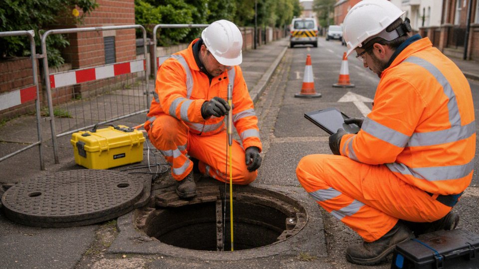
The practical operating conclusion is simple: 10/2 underground wire is often a good fit for short to moderate 120 V runs and longer 240 V runs, but long distance, high load, motor starting, subpanels, and future expansion are the common reasons to upsize or change conductor count. I have seen more money wasted re-trenching a “cheap” underground run than was saved on the first cable purchase.
For procurement, keep a small project file before issuing the purchase order:
- Marked cable type and conductor material
- Applicable standards and certification requirements
- Factory test reports or inspection documents required by the buyer
- Reel length and packaging requirements
- Installation route and approximate trench length
- Load schedule, voltage, breaker size, and continuous-load status
- Destination market and approval requirements
- Confirmation from the authority having jurisdiction, licensed designer, or project electrical engineer
If you are planning a project, bulk purchase, or export order, send Jinda’s technical team the load current, voltage, one-way distance, burial method, destination market, required standards, and any project drawings or load schedule available. Jinda can help review the application information and verify the proper underground cable specification for quotation and supply planning.