An underground run that looks simple on the sketch can turn into dim lights, nuisance trips, weak tool startup, or a pump that runs hot because the voltage at the far end is lower than expected. The trench, conduit, fittings, backfill, and inspection time often cost more than the wire itself, so discovering the run is too long after burial is an expensive mistake. The right answer starts with load current, one-way distance, circuit voltage, conductor material, and the wiring method—not just “12 gauge.”
For 12 AWG copper underground, a practical 3% voltage-drop limit is roughly 55 ft one-way on a 120 V, 20 A circuit, about 75 ft at 15 A, and around 110 ft at 240 V, 20 A. The legal ampacity may still be acceptable, but voltage drop usually sets the useful distance.
That range surprises people because burial depth, UF-B versus THWN-2 in PVC, and GFCI rules get most of the attention. Those details matter for code compliance and durability, but the distance question is mostly an electrical math problem with some jobsite messiness added: warm conductors, long trench routes, future load creep, and inspectors who want the installation to match the local rulebook.

Voltage drop limits
For 12 AWG copper underground circuits, voltage drop is usually the first engineering limit you hit before any fixed “maximum distance” rule. At a 3% branch-circuit design target, a 120 V, 20 A load is comfortable only to about 57 ft one-way, while the same wire on a 240 V, 10 A load can reach roughly 227 ft one-way.
Voltage drop is the voltage lost as current pushes through conductor resistance. The part that gets missed in field estimates is the return path. If the trench from the panel to the shed is 80 ft, the current path is not 80 ft; for a normal two-wire circuit it is about 160 ft of copper, because current goes out on one conductor and returns on the other. That is why a tape-measured trench length can look harmless until the load is switched on and the tool, pump, or charger sees low voltage.
For calculation, 12 AWG copper is commonly taken as about 1.588 ohms per 1,000 ft at 20°C, or 0.001588 ohms per foot. That is a clean reference number, not a promise that the installed cable will always behave exactly that way. Copper resistance rises as conductor temperature rises. A conductor running warm in a conduit with several current-carrying conductors, in sun-heated PVC before it enters the ground, or near its ampacity limit will have higher resistance than the 20°C value. Underground sections may be cooler than attic wiring, but the whole circuit length matters, including the vertical risers and panel terminations.
The plain-English formula is:
Voltage drop = 2 × one-way length × current × conductor resistance per foot
For 12 AWG copper using the 20°C baseline:
Voltage drop = 2 × one-way length in feet × load amps × 0.001588 ohms/ft
The “2” is there because the current travels the complete circuit path, not just the visible trench. For a 240 V load, the same conductor resistance applies, but the allowed 3% voltage drop is larger in volts: 7.2 V on a 240 V circuit instead of 3.6 V on a 120 V circuit. That is why 240 V equipment can often tolerate a longer run at the same current and conductor size.
The 3% branch-circuit voltage drop figure is a design recommendation widely used by electricians and engineers for usable voltage at the equipment. The 5% figure is commonly used for the combined feeder plus branch-circuit drop. These are good design targets, not a simple pass-fail distance rule by themselves. A local inspector may care about code compliance items such as conductor type, burial depth, GFCI protection, box fill, conduit fill, wet-location insulation, and overcurrent protection before they ever comment on voltage drop. The equipment, however, may care immediately.
A lamp may only look a little dim. A motor may run hotter, start slower, or fail to start under load. A battery charger may draw current in pulses and complain long before the arithmetic looks terrible. That is the difference between being “wired” and being well supplied.
Practical 3% distance benchmarks for 12 AWG copper
These distances are one-way trench or route lengths, calculated from the panel or supply point to the load, using 12 AWG copper at about 1.588 ohms per 1,000 ft and a 3% voltage drop target. They are engineering benchmarks, not a substitute for checking the actual circuit layout, conductor temperature rating, terminations, and the equipment manual.
| Circuit voltage | Load current | 3% voltage drop allowed | Approximate one-way distance with 12 AWG copper |
|---|---|---|---|
| 120 V | 20 A | 3.6 V | 57 ft |
| 120 V | 16 A | 3.6 V | 71 ft |
| 120 V | 15 A | 3.6 V | 76 ft |
| 120 V | 10 A | 3.6 V | 113 ft |
| 240 V | 20 A | 7.2 V | 113 ft |
| 240 V | 16 A | 7.2 V | 142 ft |
| 240 V | 15 A | 7.2 V | 151 ft |
| 240 V | 10 A | 7.2 V | 227 ft |
The counter-intuitive part is that the breaker size does not tell you the voltage drop by itself. A 12 AWG copper circuit on a 20 A breaker might feed a 6 A gate operator, a 9 A lighting load, a 12 A charger, or a continuous 16 A load. The wire and breaker may be identical in all four cases, but the voltage drop is proportional to the actual current. Cut the current in half and the voltage drop is cut in half.
That is why a lightly loaded 12 gauge underground run can be much longer than a fully loaded 20 A circuit without creating the same voltage problem. A 120 V receptacle circuit expected to run a full 20 A load should be treated as a short run unless upsized. A 240 V control circuit or small fixed load drawing 8 to 10 A may be acceptable at a much greater distance, provided the voltage at the equipment remains inside the manufacturer’s required range.
There is a trade-off here that shows up in purchasing decisions. Staying with 12 AWG keeps material cost down and makes pulling easier, especially through residential-size PVC with bends that were installed by someone who thought future maintenance was a myth. Upsizing to 10 AWG or 8 AWG costs more and can force larger conduit, larger boxes, different terminals, or a revised pull plan. The preferred choice flips when the load is steady, the run is long, the equipment is voltage-sensitive, or future expansion is likely. Saving a small amount on copper is poor economics if the result is nuisance trips, cooked motor windings, dim lighting, or a trench that has to be reopened.
Motors, compressors, pumps, welders, and battery chargers deserve extra margin because their current behavior is not as friendly as a simple heater or incandescent lamp. A pump motor can pull several times its running current while starting. That high inrush current produces a temporary voltage sag across the same conductor resistance. If the motor is starting against pressure, in cold weather, or after sitting for months, the sag can be enough to make the contactor chatter or the motor accelerate slowly. Slow acceleration means the motor stays in the high-current region longer, which creates more heat. I have seen this blamed on “bad pumps” when the wiring was the weak link.
Welders are another common trap. The nameplate and plug may tempt people into thinking only in breaker size, but welding current demand is intermittent and ugly from a voltage-quality standpoint. Battery chargers, especially larger modern chargers, can also draw nonlinear current rather than a smooth sine-wave load. The arithmetic voltage drop formula still gives the conductor resistance loss, but it may not fully describe how the equipment reacts. For these loads, I would not design right up against the 3% number unless the equipment manufacturer confirms it is acceptable and the supply voltage is known to be strong.
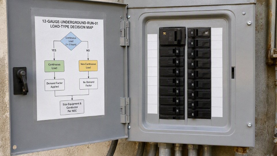
Continuous loads also need care. In many electrical design contexts, a continuous load is treated differently for conductor and overcurrent sizing, commonly using a 125% factor where applicable. That is a code and equipment-selection issue separate from the voltage drop calculation, but it affects the same decision. A 16 A continuous load on a 20 A branch circuit is already using the circuit heavily; putting it at the far end of a long 12 AWG underground run leaves little cushion for warm conductors, low utility voltage, aging terminations, or a future owner adding one more device because “there was an outlet there.”
For rough planning, I would start considering 10 AWG when a 120 V 12 AWG run is getting past the 50 to 75 ft range with meaningful load. I would look harder at 8 AWG, a subpanel feeder, or a higher-voltage equipment option when the run moves into the 100 ft-plus range and the load is not small. Those are not code cutoffs; they are practical warning zones. The actual answer depends on:
- Load current during normal operation
- Starting or surge current
- One-way route length, including vertical rises and panel routing
- 120 V versus 240 V utilization voltage
- Copper versus another conductor material
- Conductor insulation temperature rating and wet-location suitability
- Number of current-carrying conductors in the raceway
- Conduit material, fill, and installation environment
- Minimum voltage required by the equipment manufacturer
- Future expansion plans
If the calculated drop is already near 3% on paper, 12 AWG is usually no longer the comfortable choice for an underground run that feeds motors, chargers, shop tools, or anything expected to grow later. The calculation is based on clean assumptions; the installation will add tolerances, temperature, connection resistance, and sometimes a few undocumented feet of route length. That is where 10 AWG, 8 AWG, or a properly designed feeder stops being overkill and starts being cheaper than troubleshooting.
Breaker and ampacity rules
12 AWG copper underground branch-circuit conductors are commonly protected at a maximum of 20 A, but that ampacity rule is not the same thing as a distance rule. The breaker protects the conductor from overheating under overcurrent conditions; it does not make a long run deliver acceptable voltage at the load.
Installing a larger breaker does not compensate for voltage drop on a long 12 AWG underground run.True
A larger breaker raises the overcurrent protection threshold, but the conductor resistance remains the same. The load may still receive low voltage, while the wire may no longer be properly protected against overheating.
For normal copper building wire, the familiar field rule is simple: 14 AWG on 15 A, 12 AWG on 20 A, 10 AWG on 30 A. That rule has exceptions, and inspectors do not like shortcuts around them. Underground installations bring in conductor insulation type, wet-location rating, raceway fill, terminals, burial method, and sometimes local amendments. UF-B direct burial, individual THWN-2 conductors in PVC, and conductors in metal raceway are not treated identically in every detail, even if they all appear to be “12 gauge underground wire” on a material list.
The first separation to keep clear is this:
| Item | What it controls | What it does not solve |
|---|---|---|
| Breaker rating | Maximum permitted overcurrent before the breaker trips | Voltage drop on a long feeder or branch circuit |
| Conductor ampacity | Heat the conductor can safely carry under rated conditions | Whether the load receives full operating voltage |
| Voltage drop calculation | Delivered voltage at the equipment | Legal permission to overload the conductor |
| Equipment nameplate load | Actual current demand used for sizing | The breaker size by itself |
A 20 A breaker on 12 AWG copper may be code-normal for many branch circuits, but it still allows a poor installation if the run is long and the load is sensitive. I have seen small pumps, gate operators, heaters, and outdoor refrigeration loads wired “correctly” from a breaker standpoint but still nuisance-trip, run hot, or start weakly because the actual voltage at the equipment sagged under load. The copper was not magically undersized by ampacity; it was undersized for the distance and load behavior.
Continuous load planning is where many small underground circuits get misjudged. In many code frameworks, a continuous load is one expected to run for three hours or more, and the common design treatment is to load the breaker to no more than 80% of its rating unless the equipment and overcurrent device are specifically rated otherwise. That means:
- A 15 A circuit is commonly planned around 12 A for continuous load.
- A 20 A circuit is commonly planned around 16 A for continuous load.
- A load that cycles briefly may be treated differently from one that runs all afternoon.
- Motor loads need attention to starting current, not only running amperage.
- Heating, lighting, battery charging, and process loads often behave more like continuous loads than owners expect.
For distance planning, use the equipment load current, not just the receptacle size or breaker handle rating. A 20 A outdoor receptacle feeding a 6 A control panel is a different voltage-drop problem than the same receptacle feeding a 16 A heater. The trench length did not change, but the voltage drop roughly scales with current, so the load drives the electrical result.
Aluminum deserves its own warning. 12 AWG aluminum is not a like-for-like substitute for 12 AWG copper in typical small branch-circuit work. Aluminum has higher resistance than copper at the same gauge, needs terminals listed for aluminum where permitted, and is more sensitive to workmanship details such as oxide control, torque, and thermal cycling. Larger aluminum feeders are common and perfectly serviceable when designed properly; small aluminum branch circuits are usually not the place to improvise, especially underground where access later means digging, pulling, or opening wet boxes.
Terminal temperature ratings also matter. Conductors may have insulation marked for 75°C or 90°C, but the usable ampacity is often limited by the equipment terminals. Many small breakers, receptacles, switches, and disconnects are effectively governed by 60°C termination limits for smaller conductors unless the equipment is marked otherwise. In practice, that means you cannot just look at the highest ampacity column for the insulation and claim extra capacity. The weakest rated connection point in the circuit can control the allowable ampacity.

Derating is the next trap. Underground conduit can look generous on the drawing, then become a heat-management problem once several circuits are pulled through the same raceway or routed through hot areas before entering the trench. Ampacity adjustment may be needed when any of these are present:
- Multiple current-carrying conductors in the same raceway.
- Shared neutrals, depending on circuit type and harmonic content.
- High ambient temperature at terminations or exposed conduit sections.
- Bundled cable before entering the trench.
- Rooftop, wall-mounted, or sun-exposed conduit transitions.
- Crowded pull boxes, small enclosures, or equipment cabinets that run warm.
- Mixed power and control layouts that tempt installers to overfill conduit.
The mechanism is basic but unforgiving: current creates heat in the conductor, insulation slows heat transfer, and surrounding air or soil must carry that heat away. Put more loaded conductors in the same raceway, or pass the raceway through a hot equipment enclosure, and the conductor starts from a higher thermal baseline. The breaker may not trip because there is no fault; the installation can simply operate hotter than intended for years, which ages insulation and terminations.
There is a trade-off between keeping 12 AWG and upsizing the conductor. Staying with 12 AWG reduces material cost, conduit fill, pulling effort, and termination difficulty. Upsizing to 10 AWG or larger may reduce voltage drop and heat, but it can require larger conduit, larger boxes, different lugs, and more careful procurement so the field crew does not end up shaving strands or fighting a receptacle that was never designed for the conductor. The preferred choice flips when the load is near the circuit limit, the run is long, the load starts hard, or the circuit will be continuous.
The one thing not to do is install a 25 A or 30 A breaker on 12 AWG copper just because the load is far away and starts poorly. That defeats the conductor protection the breaker is supposed to provide. If the equipment needs better voltage, solve it with a larger conductor, a higher distribution voltage where appropriate, a local feeder and subpanel, reduced load, or a different equipment arrangement verified against the applicable code and equipment manuals.
The breaker size tells you the maximum protected circuit rating; it does not tell you the underground run is electrically sound. Start with the equipment nameplate, duty cycle, starting behavior, conductor material, insulation rating, terminal markings, raceway conditions, and inspection rules, then calculate distance from the actual load current rather than from the breaker label.
Underground wiring methods
| Method | Typical cable or conductor choice | Where it fits best | Main tradeoff |
|---|---|---|---|
| UF-B direct burial cable | Factory-assembled underground feeder cable | Simple residential branch circuits, sheds, lights, small outdoor loads | Lower raceway cost, but difficult to replace and more exposed to dig-in damage |
| Individual conductors in PVC conduit | Wet-rated copper conductors such as THWN-2, XHHW-2, or another approved marking | Most planned underground runs where serviceability matters | More trench and conduit work, but easier replacement and future upsizing |
| Individual conductors in rigid metal conduit or IMC | Wet-rated conductors in heavy-duty metal raceway | Shallow areas where allowed, exposed risers, driveway or damage-prone zones | Excellent mechanical protection, higher material cost and corrosion planning |
| Short flexible liquidtight transitions | Wet-rated conductors in listed liquidtight flexible conduit | Final connection to equipment, pumps, HVAC units, or moving/vibrating terminations | Useful for short protected sections, not a substitute for an entire underground raceway unless specifically permitted |
The first mistake I still see on small jobs is someone pulling ordinary indoor NM-B through underground pipe because “it’s in conduit, so it’s protected.” That is not how inspectors usually view it. Underground conduit is treated as a wet location, and the conductors or cable inside must be listed and marked for that environment.
Ordinary indoor NM-B cable is approved for underground conduit if the conduit is sealed.False
Underground raceways are normally considered wet locations. NM-B is intended for dry locations and is not approved for direct burial or underground wet-location conduit unless a specific local rule or product listing says otherwise, which is not typical.
UF-B direct burial versus conductors in conduit
UF-B is the straightforward option: trench, lay the cable at the required depth, protect the rises, backfill correctly, and call for inspection. For a short run to a post light or a small shed circuit, it can be a clean solution. There is no conduit fill calculation for the buried portion, and the material list is short.
The downside shows up later. If the cable is damaged by a shovel, settlement, tree roots, or a sharp rock that was left in the trench, repair means excavation. If the owner later wants to change a 120 V lighting circuit into a larger feeder, the old cable usually does not help much. You dig again.
Conduit with individual conductors costs more up front, especially once fittings, sweeps, glue, straps, expansion fittings, and larger trench width are counted. But it gives you:
- Better mechanical protection, especially with proper schedule selection and protected risers.
- Replaceable conductors if insulation is damaged or the load changes.
- A clearer route that future maintenance people can trace.
- Easier upsizing from 12 AWG to larger conductors, if the raceway was sized with that in mind.
- Cleaner inspection conversations because conductor markings, raceway type, burial depth, and terminations are visible and conventional.
In practice, I lean toward conduit for anything the owner may regret burying permanently: long runs, hardscaped areas, driveways, commercial yards, pump circuits, gates, signage, and any place where future load growth is likely. Direct burial still has its place, but it rewards careful trench work and punishes casual backfill.
Wet-location conductor ratings inside underground conduit
PVC conduit may look dry when you install it. Six months later it will usually have condensation, groundwater seepage at fittings, or moisture from temperature cycling. Even a glued raceway system breathes a little through terminations, boxes, and seasonal expansion.
That is why individual conductors in underground conduit normally need a wet-location insulation rating. Common markings include:
- THWN-2: widely used copper building wire for wet locations, often dual-marked with THHN/THWN-2.
- XHHW-2: cross-linked polyethylene insulation, often preferred where abrasion resistance, heat tolerance, or industrial familiarity matters.
- Other approved wet-location markings: acceptable only when the product listing and local code support the installation.
Do not assume every spool in the shop is acceptable just because it is the right gauge and color. Look at the print legend on the insulation. I have seen crews grab dry-location wire from a maintenance crib because it was “only for a short underground stub.” That short stub becomes the weak link, and if it fails, troubleshooting starts with megger readings, nuisance trips, and a trench nobody budgeted to reopen.
Raceway choices underground
PVC electrical conduit is the common workhorse for residential and light commercial underground runs. It is nonmetallic, corrosion-resistant, easy to cut, and forgiving in normal soil. The weak points are physical damage at risers, poor glue joints, too many tight bends, and thermal movement on exposed vertical sections. Use long-radius sweeps where pulling distance is meaningful; plumbing elbows are not a substitute for electrical sweeps.
Rigid metal conduit and intermediate metal conduit offer stronger mechanical protection and may qualify for reduced cover in some code tables. They are useful where the raceway comes out of the ground, crosses an exposed service area, or passes through a zone where a mower, forklift, trailer hitch, or snowplow can hit it. The tradeoff is cost, labor, threading or listed fittings, corrosion control, bonding continuity, and the fact that underground metal work needs more discipline than simply “burying pipe.”
Flexible liquidtight conduit belongs in short transitions, not as the default answer for a long trench. It is handy between a rigid raceway and vibrating equipment, a pump control box, an air-conditioning unit, or a motorized gate operator. The allowed length, burial suitability, fittings, and support requirements must be checked against the listing and local rules. If someone proposes 80 feet of flexible liquidtight because it avoids bending PVC, slow the job down and review it.
Burial-depth planning categories
Burial depth is not just an electrical preference; it is an inspection, damage-risk, and civil-work issue. Exact cover requirements depend on the locally adopted electrical code, circuit type, raceway type, GFCI protection, location, and sometimes utility or site rules.
Common planning categories look like this:
| Installation category | Planning expectation | Field comments |
|---|---|---|
| Direct burial UF-B cable | Often requires deeper cover than raceway methods | Protect against rocks, settlement, and later digging; sleeve where it rises from grade |
| PVC electrical conduit | Commonly falls in an intermediate cover category | Good general-purpose choice, but exposed risers need physical protection |
| Rigid metal conduit or IMC | May be allowed with less cover in some installations | Higher protection, higher cost; verify corrosion and bonding details |
| Certain residential GFCI-protected branch circuits | May qualify for reduced cover where local code permits | Do not assume this applies to feeders, commercial work, driveways, or unprotected circuits |
Driveway crossings deserve extra attention. Soil compaction, vehicle loading, frost movement, and future paving work all change the risk picture. In rocky ground, the code minimum depth may still be a poor construction depth if the raceway ends up sitting against angular stone. In wet clay, a shallow trench can become a water channel. The inspector may approve the electrical depth, but the site can still be unfriendly to the installation.
Trench preparation and route control
A good underground electrical run starts before the wire is even on site. The best material selection will not save a trench full of sharp rubble and mystery utilities.
Use a field checklist like this:
- Call for utility locating and verify private utilities. Public locates may not mark irrigation, site lighting, old feeders, propane lines, or low-voltage controls.
- Remove sharp rocks and construction debris. A few inches of clean bedding material is cheap compared with finding a fault under finished landscaping.
- Avoid standing water pockets where practical. You cannot make underground conduit dry, but you can avoid creating a sump at a low spot with poor drainage.
- Maintain separation from other utilities. Electrical, gas, water, communications, and drainage lines should not be casually bundled in one trench without approved spacing and coordination.
- Use warning tape above the run. Place it high enough that a future shovel or trencher hits the warning before it hits the cable or conduit.
- Document the route. Photos before backfill are useful. Measurements from fixed points are better than “near the fence,” especially after the fence gets moved.
- Protect risers and transitions. Many underground failures happen within the first couple of feet above or below grade, not in the neat middle of the trench.
For commercial or multi-building sites, I like recording route coordinates or at least marked-up as-built drawings. It feels excessive on bid day; it feels cheap five years later when someone is cutting for a drain line.
Conduit fill, bends, and pulling limits
Choosing the smallest raceway that technically fits is usually false economy. Conductors pull harder than the table suggests once the trench has a few sweeps, a slight misalignment, damp conduit, and a helper feeding wire at a bad angle. A 12 AWG circuit may not need much space electrically, but installation quality improves when the raceway is sized for the pull, not just the conductor count.
Check these before buying conduit:
- Number of current-carrying conductors, neutrals, grounding conductors, and spares.
- Conduit fill limits from the applicable code tables.
- Total bend count between pull points.
- Pulling tension and sidewall pressure for longer runs.
- Box and handhole locations where pulling access is needed.
- Future upgrade path, such as moving from 12 AWG to 10 AWG or adding a control pair where permitted.
- Whether separate systems, such as power and communications, must be in separate raceways.
The mechanism is simple: every bend increases friction, and every tight bend concentrates pulling force against the insulation. That can scrape jackets, stretch conductors, crack old insulation during replacement, or make a future pull practically impossible. Upsizing from 1/2 inch to 3/4 inch PVC on a small branch circuit may look like wasted money on a material spreadsheet, but it can save a crew from fighting a pull in the rain with a fish tape, dish soap, and bad language.
The point stops holding when the route is very short, straight, accessible, and unlikely to change. For a short residential sleeve under a walkway, the smallest approved raceway may be perfectly reasonable. For a long underground run feeding equipment that may grow, conduit size is one of the cheapest decisions to make generously before the trench is closed.
Load type considerations
A 12 gauge underground run that works well for a small lighting load may be a poor choice for a receptacle, pump, detached garage, or future EV charger. The wire size has to be judged against the load profile, not just the breaker size: steady current, starting current, duty cycle, voltage tolerance, and what someone may plug in five years from now.
Lighting circuits
LED landscape and area lighting often pull so little current that voltage drop looks harmless on paper. A few hundred watts at 120 V may be only 2–4 A, so a long 12 AWG copper run can still deliver acceptable voltage at the end of the circuit.
The catch is that modern lighting is not just a resistive load. LED drivers, photocells, occupancy sensors, and dimmers can react badly to marginal voltage, poor neutral connections, long shared runs, or electrical noise from other equipment. In practice, nuisance flicker shows up before anything “fails.” It may happen only at dusk when a photocell changes state, when a refrigerator in a shed starts, or during cold weather when driver electronics behave differently.
For lighting, check:
- Total connected wattage, not just fixture count
- Whether fixtures use electronic drivers, dimmers, photocells, or smart controls
- Voltage required at the farthest fixture under full load
- Whether the circuit also serves receptacles or motors
- Splice quality in underground boxes, because one damp wirenut can imitate a voltage-drop problem
Low current gives you distance, but it does not excuse sloppy layout. I would rather see outdoor lighting split into logical zones than one long daisy chain with every splice buried under mulch.
Outdoor receptacles
Outdoor receptacles are the worst load to “average” because the future load is unknown. Today it may be a battery charger and holiday lights; later it may be a pressure washer, portable heater, miter saw, smoker, or dehumidifier in a damp outbuilding.
A 20 A, 120 V receptacle circuit on 12 gauge wire can be legal from an ampacity standpoint, but long distance changes how it behaves. Voltage drop reduces tool torque, makes motors run warmer, and can cause nuisance tripping or poor performance on equipment with electronics. A pressure washer that starts acceptably near the house may grunt, trip, or shorten its motor life at the end of a long underground branch circuit.
For general-purpose outdoor receptacles, design conservatively:
- Assume the receptacle may see the full circuit rating at some point.
- Keep voltage drop tighter than you would for decorative lighting.
- Avoid sharing long receptacle runs with sensitive lighting controls.
- Use weather-resistant devices, proper in-use covers, and GFCI protection as required by the local code.
- Confirm burial depth and wiring method with the inspector before trenching.
If the load is unknown, size the underground run for the worst reasonable plug-in load, not the small device planned on day one.
Detached garage or shed circuits
A simple 12 gauge branch circuit can be fine for a small shed with lights, a garage door opener, and a couple of convenience receptacles. It becomes a poor fit when the building starts acting like a workshop.
The design usually flips from “branch circuit” to “feeder and subpanel” when you expect several of these at the same time:
- Bench tools, saws, grinders, or dust collection
- Space heating or air conditioning
- A refrigerator, freezer, or compressor
- EV charging, even at modest levels
- Exterior lighting plus indoor receptacles
- Future circuits that need separate protection
The trade-off is simple: 12 gauge is cheaper and easier to pull, but it gives you little room to grow. A feeder with larger conductors, a grounding electrode system where required, and a small subpanel costs more up front, yet it avoids the ugly retrofit where the owner calls you back after the concrete walk, driveway edge, or finished landscaping is already in place.
Pumps and motors
Pumps and motors need separate attention because their highest electrical demand occurs during starting, not steady running. A motor may run at a moderate current after it is up to speed, but starting current and locked-rotor current can be several times higher. The exact value is motor-specific, so use the pump or motor nameplate and manufacturer data rather than a generic multiplier.
Low voltage at a motor reduces starting torque. That is the mechanism that causes trouble: the motor takes longer to accelerate, current stays high longer, windings heat, overload devices trip, and the motor may fail early if the condition repeats. Submersible pumps, well pumps, sewage ejectors, pond pumps, and long runs to remote equipment are common places where a “12 gauge should be enough” assumption turns expensive.
Check these items before accepting 12 gauge for a pump or motor:
- Running full-load current
- Starting or locked-rotor current
- Manufacturer voltage tolerance at the motor terminals
- One-way trench distance and circuit voltage
- Control box or pressure switch location
- Duty cycle and ambient temperature
- Whether nuisance trips would create flooding, loss of water, or process downtime
Where the motor is critical, measure or calculate voltage at the motor terminals during start, not only during steady running.
Gate openers and control circuits
Gate operators often look easy because standby and control current are low. The long-run issue appears when the motor actuates, the battery charger is recovering, accessories are active, and voltage sags at the same time.
For gate systems, separate the load types mentally:
- Motor power for the operator
- Battery charging circuit, if used
- Keypads, card readers, loops, intercoms, and sensors
- Low-voltage signal wiring
- Surge protection and grounding requirements
A long 12 gauge power circuit may be acceptable for a modest gate operator, but confirm the operator’s input voltage range and starting behavior. Voltage drop that is harmless at idle can show up as slow opening, fault codes, weak battery recovery, or intermittent service calls after storms.
EV charging and high-duty equipment
12 gauge underground wire is usually the wrong design basis for larger EV charging, welders, large air compressors, kilns, heavy heaters, or sustained high-current loads. Some small 120 V EV charging equipment may operate on a 15 A or 20 A circuit if the manufacturer permits it, but that is not the same as designing a useful EV charging installation.
High-duty loads punish marginal wire sizing because they run near capacity for long periods. Heat has time to build, voltage drop persists for hours, and small losses become real energy cost and thermal stress. For continuous loads, conductor sizing, breaker sizing, terminal temperature ratings, and voltage drop need to be checked together against the applicable code and equipment instructions.
Irrigation and landscape systems
Irrigation work often mixes two very different wiring categories: power circuits and low-voltage control wiring. They should not be treated as interchangeable just because they are in the same trench.
Typical categories include:
- 120 V or 240 V power for pumps, controllers, receptacles, or lighting transformers
- 24 V irrigation valve control wiring
- Sensor wiring for rain, flow, or soil moisture devices
- Landscape lighting secondary wiring
- Communication or control cables for smart systems
Improperly mixing power conductors and low-voltage control wiring in the same raceway can violate code, defeat insulation separation requirements, create interference, and make troubleshooting miserable. Use wiring methods and separation rules that match the voltage class and insulation rating. If a raceway is shared, verify that every conductor and system is permitted to be there under the applicable code and product listings.
Future expansion
One of the most common procurement mistakes is buying for the present load and ignoring the trench value. Cable is not the only cost underground. Excavation, conduit, bedding, backfill, pavement cuts, landscaping repair, permits, and downtime often cost more than the conductor difference.
If there is a realistic chance of a future workshop, extra receptacles, larger pump, EV charging point, or subpanel, price the larger raceway or feeder before committing to 12 gauge. Even if the first installation uses smaller conductors, upsizing conduit where permitted can preserve options. The boundary is practical and code-based: oversized plans still have to meet conduit fill, burial, pulling tension, grounding, and inspection requirements, but reopening a trench because the original cable was sized for one light and one outlet is usually the most expensive way to save money.
Cable construction choices
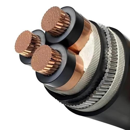
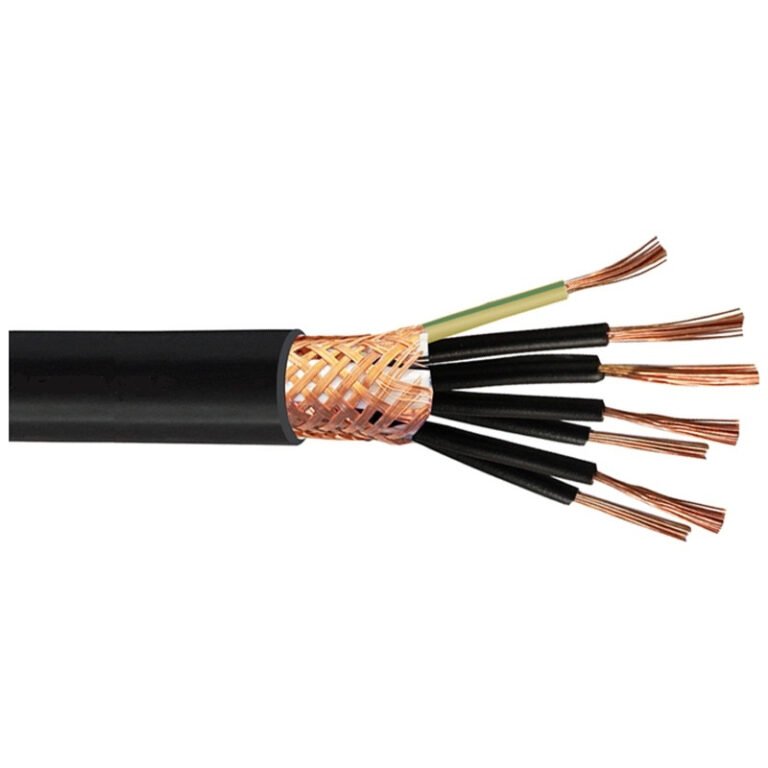
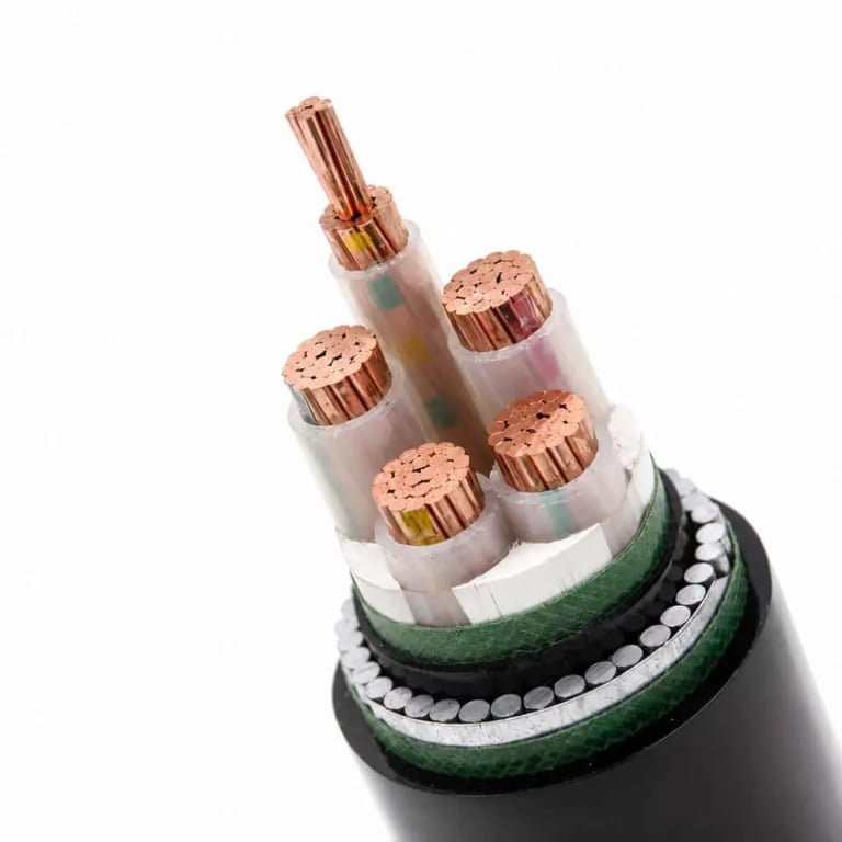
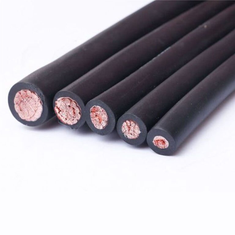
A good 12 gauge underground specification is not just “12 AWG.” It should define the conductor, insulation, jacket, voltage and temperature ratings, wet-location suitability, listing or standard basis, markings, and traceability. Two cables with the same nominal gauge can behave very differently in the trench, in conduit, at terminals, and during inspection.
What to specify beyond gauge
For procurement, I would put these items on the cable datasheet or purchase order before discussing price:
- Conductor material: Usually copper for 12 AWG branch circuits, though some projects consider aluminum only at larger sizes. Do not mix copper assumptions into an aluminum quote; resistance, termination practice, and allowed use change.
- Conductor construction: Solid or stranded, with the applicable stranding class if stranded. This affects pulling, flexibility, and termination hardware.
- Insulation type: Common North American underground branch-circuit work may use UF-B cable or individual wet-rated conductors such as THWN-2 in conduit. IEC-style projects may specify different insulation systems entirely, so the governing standard matters.
- Jacket material: Direct-burial cable needs a jacket system suited to soil contact and mechanical handling. Conductors pulled in conduit rely more on the conduit for mechanical protection but still need wet-location insulation.
- Voltage rating: Match the circuit and standard. Many building-wire products are marked for 600 V in NEC-style practice, but the marking must be verified on the actual product, not assumed from the category name.
- Temperature rating: Termination temperature limits often control the usable ampacity, even if the insulation has a higher rating. Panels, receptacles, breakers, and lugs have their own rules.
- Wet-location rating: Underground conduit is treated as wet in NEC-style work because water enters through condensation, joints, and grade changes. A “dry location” wire in buried conduit is asking for trouble.
- Flame behavior where applicable: Flame or smoke requirements may apply where the cable transitions into buildings, equipment rooms, tunnels, ducts, or other regulated spaces.
- Marking requirements: Cable type, size, conductor material, voltage rating, temperature rating, manufacturer identification, listing marks, production code, and length markings should be legible and durable enough for receiving inspection.

Solid vs. stranded 12 AWG copper underground
Solid 12 AWG copper is common in residential branch-circuit cable because it is simple, inexpensive, and works well under many screw terminals and device clamps designed around solid building wire. It also holds shape, which electricians often like inside boxes. The drawback shows up during long conduit pulls, bends, and vibration-prone equipment connections: solid wire is stiffer and less forgiving.
Stranded 12 AWG copper pulls easier through PVC conduit, especially where the route has several sweeps, a slightly dirty duct, or a pull string that was left in by the civil crew six months earlier. It handles repeated flexing better than solid, though normal building wire is still not the same thing as high-flex machine cable. The trade-off is termination discipline. Fine or compact stranding may require listed terminals, ferrules where permitted, or compression lugs suited to the conductor class. A back-wired receptacle that happily accepts solid copper may not be approved for the stranded construction being purchased.
For short, simple outdoor branch circuits, solid UF-B or solid conductors are often accepted by convention where the wiring method permits it. For longer conduit runs, crowded raceways, or panels with multiple field terminations, stranded conductors can save labor and reduce insulation damage during pulling. That preference stops holding if the devices, breakers, splice connectors, or local inspection practice do not accept the selected stranded construction.
Why wet-location construction matters underground
Moisture underground is not just rainwater. Conduit “breathes” with temperature swings, pulling humid air in and out; then condensation collects at low points. Direct-burial cable sees soil moisture, fertilizer salts, hydrocarbons in some industrial yards, acidic or alkaline soil chemistry, and physical abrasion during backfill. If the insulation or jacket was not designed for that environment, degradation may start invisibly.
The mechanism is usually slow but expensive. Water tracks through jacket nicks, poor end sealing, damaged insulation, or weak jacket adhesion. Once moisture reaches the conductor interface, insulation resistance can fall, leakage current rises, GFCI devices may nuisance trip, and copper corrosion can increase termination heating. In conduit, the cable may look protected from a distance while sitting in a wet plastic pipe for years.
Good jacket integrity is not only about thickness. It depends on compound selection, extrusion stability, concentricity, cooling control, adhesion, and handling during packaging. A cable with a thin spot may pass a casual visual check and still become the failure point after a hard pull around a sweep. This is where cheap cable often costs more than it saved.
Underground conduit should be treated as a wet environment when selecting conductor insulation.True
This reflects common NEC-style installation practice because buried raceways are subject to water entry and condensation. The exact rule reference and permitted wiring method must be verified against the current code adopted by the project jurisdiction.
Documentation buyers should request
For one pallet of cable, missing paperwork is annoying. For a container shipment, a utility yard, or a multi-building site, it becomes a schedule risk. The buying file should include:
- Applicable compliance evidence
Listing, certification, or declaration documents matching the intended market and installation method, such as NEC-style, IEC-style, or local hybrid requirements. - Factory test reports
Electrical test records relevant to the product type, including voltage withstand or spark testing where applicable. Do not accept a generic “passed QC” note as a substitute for batch-specific evidence. Conductor resistance data
Resistance is the practical fingerprint of conductor area and material quality. Undersized copper may still be shiny, flexible, and nicely printed.Insulation and jacket thickness records
Average thickness alone is not enough if minimum thickness is poor. Ask how the factory controls eccentricity and minimum wall.Packaging labels and reel identification
Labels should match the purchase order, cable markings, length, batch number, and destination requirements.Batch traceability
The supplier should be able to trace finished cable back through conductor, compound, production run, and test records. This matters when a field issue affects only part of a shipment.
For bulk international procurement, Jinda’s value is not only making cable; it is controlling repeatability across production, documentation, technical communication, and shipment preparation. With established manufacturing scale, multiple production bases, technical support, and export experience, the practical discussion should include consistent conductor diameter, stable insulation extrusion, repeatable electrical testing, export packaging, palletization, private labeling if required, and how batch records will be supplied with the order.
Low-cost cable risks that show up after delivery
The most dangerous cable problems are the ones that pass a quick receiving glance. I have seen buyers focus on price per meter and ignore the details that decide whether the electrician can actually install the product without scrap.
Common risks include:
- Undersized conductor area: Lower copper content increases resistance, worsens voltage drop, and can raise operating temperature.
- Inconsistent insulation thickness: Thin sections are more vulnerable during pulling and long-term wet exposure.
- Poor jacket adhesion or weak jacket compound: The jacket scuffs, splits, or peels during handling and backfill.
- Inaccurate meter marking: Crews cut wrong lengths, inventory records drift, and claims become hard to prove.
- Weak reels, cartons, or pallet wrapping: Cable arrives crushed, wet, tangled, or with unreadable labels.
- Missing or mismatched documentation: Inspection, customs clearance, and project handover slow down even if the cable itself is usable.
Cable selection should follow the governing standard and the installation jurisdiction. A project based on NEC-style practice, IEC-style practice, or a local hybrid specification may use different type designations, test requirements, conductor classes, colors, and approval marks. Do not assume a 12 gauge product approved for one market is automatically acceptable in another; the nominal gauge is only one line in the specification.
Sizing calculation workflow
- Identify the actual load, not just the breaker size.
Start with the equipment nameplate, installation manual, or measured current from a comparable unit. Record:- Full-load current
- Starting or inrush current, if it is a motor, pump, compressor, transformer, or LED driver bank
- Duty cycle, especially whether the load can run for three hours or more
- Supply voltage, such as 120 V or 240 V
- Manufacturer minimum operating voltage at the equipment terminals
This step matters because voltage drop is proportional to current. A receptacle on a 20 A breaker is not automatically a 20 A load; a 9 A gate operator and a 19 A heater behave very differently on the same 12 AWG conductors. Motors deserve extra attention because they may tolerate the running voltage but stumble during start-up, especially at the end of a long underground run on a cold morning when grease is stiff and voltage is already low at the service.
Measure the true one-way conductor length.
Use the conductor path, not the neat trench dimension on the site sketch. Include:- Panel routing inside the building
- Vertical risers up and down walls or posts
- Conduit sweeps
- Offsets around footings, slabs, landscaping, or existing utilities
- Equipment whip length
- Service loops left for termination and future repair
A “100 ft trench” can easily become 118 ft of conductor by the time it leaves the panel, turns through two long-radius sweeps, rises at a pedestal, and lands in a disconnect. That extra length is not bookkeeping trivia; the electrons travel it twice in a single-phase circuit, out on the ungrounded conductor and back on the neutral or opposite phase conductor.
Choose the voltage drop target before doing the math.
A common design target is 3% voltage drop for a branch circuit at normal load. For sensitive controls, long LED lighting strings, electronic power supplies, irrigation controllers, or equipment with a published minimum terminal voltage, use the equipment requirement rather than a generic rule of thumb.The trade-off is plain: a tighter voltage drop target usually means larger copper, a shorter run, or a different circuit layout. That costs more at purchase and can require larger conduit, but it can prevent nuisance trips, dim lighting, hot-running motors, and repeated service calls. For simple resistive loads, the preferred choice may flip; accepting a little more voltage drop might be commercially reasonable if heat output reduction is tolerable and the installation remains code-compliant.
Calculate voltage drop using the round-trip circuit length.
For single-phase copper branch-circuit estimating, a common formula is:Voltage drop = (2 × K × I × D) ÷ circular mil areaWhere:
Kfor copper is commonly taken as about 12.9 at typical design conditionsIis load current in amperesDis one-way conductor length in feet- 12 AWG copper is about 6,530 circular mils
The mechanism is simple but unforgiving: doubling current or doubling distance doubles voltage drop. Raising the circuit voltage does not reduce the volts lost in the wire, but it reduces the percentage lost against the system voltage. That is why the same 12 AWG conductors may be a poor 120 V choice and a reasonable 240 V choice for the same distance and lower current.
For starting loads, run a second check using the expected starting current if the manufacturer provides it. Do not use locked-rotor current as a normal design load unless the equipment manual requires that approach; it can make a small installation look impossible on paper. Still, if the load is a pump at the far end of a rural service with already-low utility voltage, starting performance should be verified more conservatively.
A 100 ft one-way 120 V, 20 A branch circuit on 12 AWG copper is commonly above the 3% voltage drop design recommendation.True
Using the standard copper voltage-drop formula with K = 12.9 and 6,530 circular mils for 12 AWG gives roughly 7.9 V drop, or about 6.6% at 120 V.
Sample calculation: 120 V, 20 A load at 100 ft
Given:
– Circuit voltage: 120 V
– Load current: 20 A
– One-way conductor length: 100 ft
– Conductor: 12 AWG copper, about 6,530 circular mils
Calculation:
Voltage drop = (2 × 12.9 × 20 × 100) ÷ 6,530
Voltage drop ≈ 7.9 V
Percentage drop:
7.9 ÷ 120 × 100 ≈ 6.6%
Delivered voltage at full load:
120 - 7.9 ≈ 112.1 V
That does not mean the breaker will trip or the wire is automatically illegal on voltage drop alone. It means 12 AWG is not a good design choice if the project is using a 3% branch-circuit voltage drop target. In practice, I would look at reducing the load, moving to 240 V if the equipment supports it, upsizing the conductor, or placing a feeder/subpanel closer to the loads.
Sample calculation: 240 V, 10 A load at 100 ft
Given:
– Circuit voltage: 240 V
– Load current: 10 A
– One-way conductor length: 100 ft
– Conductor: 12 AWG copper
Calculation:
Voltage drop = (2 × 12.9 × 10 × 100) ÷ 6,530
Voltage drop ≈ 4.0 V
Percentage drop:
4.0 ÷ 240 × 100 ≈ 1.7%
Delivered voltage at full load:
240 - 4.0 ≈ 236 V
The physical wire loss is still there, but the percentage is much lower because the circuit voltage is higher and the current is lower. This is why 240 V pumps, heaters, and equipment motors often make more sense on longer underground runs, assuming the equipment is listed for that voltage and the installation is wired accordingly.
- Check ampacity and overcurrent protection separately.
Voltage drop does not replace code ampacity. Confirm:- Breaker or fuse rating
- Conductor ampacity for the insulation type and terminal temperature rating
- Whether the load is continuous and needs the 125% sizing treatment
- Number of current-carrying conductors in the raceway
- Ambient temperature, especially where conduit runs across hot exterior walls, rooftops, or sun-exposed structures before going underground
- Any local rule or equipment listing that limits conductor size or breaker size
A common mistake is to upsize the breaker to “fix” voltage drop. That is backwards and unsafe. If voltage drop is excessive, increase conductor size, reduce current, shorten the run, or change the circuit design; do not overfuse 12 AWG conductors.
Verify the underground wiring method and inspection details.
Before procurement, confirm:- Cable or conductor type allowed for the burial method
- Wet-location rating for conductors in underground conduit
- Required burial depth for the selected wiring method
- PVC, rigid metal conduit, or direct-burial cable requirements
- Conduit fill after all conductors are counted
- Equipment grounding conductor size and continuity
- GFCI protection where required
- Disconnecting means at equipment, pumps, outbuildings, or exterior equipment
- Warning tape, expansion fittings, corrosion concerns, and physical protection at risers
- Local inspection requirements before backfill
Underground conduit is normally treated as a wet location, even if it looks dry during installation. I have seen too many clean-looking PVC runs collect water from condensation, bad glue joints, or a low box with a missing gasket. Use conductors and cable constructions that are actually rated for the environment, not whatever happens to be on the shelf.
Compare the practical alternatives.
Once the numbers are visible, the decision becomes much less emotional. Your options are usually:- Stay with 12 AWG if ampacity, voltage drop, installation method, and equipment voltage tolerance all check out
- Reduce the connected load or avoid simultaneous operation
- Use 240 V instead of 120 V where the equipment is designed for it
- Upsize to 10 AWG, 8 AWG, or larger based on calculated voltage drop and terminal compatibility
- Install a feeder and subpanel near a group of loads
- Split loads into dedicated circuits to reduce current per run
- Relocate equipment, controls, or the power source to shorten the conductor path
Document the calculation package. At minimum, keep the load data, one-way length, voltage drop math, conductor type, breaker size, wiring method, burial detail, and any manufacturer voltage requirement. Inspectors, owners, and procurement teams all make better decisions when they can see why 12 AWG was accepted or rejected instead of inheriting a trench, a receipt, and somebody’s guess.
Frequently asked questions
How far can 12 gauge wire run underground on a 20 A breaker?
On a 20 A breaker, 12 AWG copper is usually limited by voltage drop before it is limited by breaker size. At 120 V and a full 20 A load, many designers start questioning 12 gauge once the one-way trench length gets much beyond roughly 50–75 ft, depending on the acceptable voltage drop and load sensitivity.
At 240 V, the same conductor length has about half the percentage voltage drop for the same current, so longer runs are often workable. The breaker does not “approve” the distance; it only protects against overcurrent.
Can I run 12 gauge wire 100 ft underground?
Yes, 100 ft can be acceptable if the load is modest, especially on 240 V or on a lightly loaded 120 V circuit. A 120 V circuit pulling the full 20 A through 100 ft of 12 AWG copper will usually have too much voltage drop for good practice, even though the breaker and conductor ampacity may still be code-compliant.
For lights, controls, a gate opener, or a few receptacles with intermittent loads, it may be fine. For a saw, air compressor, pump, heater, or EV-related load, I would calculate it before trenching.
Is 12 gauge wire enough for a detached garage?
It depends on what the garage is expected to do. For basic lighting, a garage door opener, and occasional hand tools, a 20 A 120 V branch circuit in 12 AWG may be adequate if the distance is not excessive.
It is usually not enough for a serious workshop, compressor, welder, mini-split, large freezer, EV charger, or future subpanel. Detached garages tend to grow loads after the trench is backfilled; if the owner is already talking about “maybe adding equipment later,” upsizing the feeder is often cheaper than reopening the yard.
Can 12 gauge wire be buried without conduit?
Only if the cable is specifically listed for direct burial, such as UF-B in many residential applications. Individual THWN-2 conductors are not direct-burial conductors by themselves; they normally belong inside an approved raceway such as PVC conduit.
Direct burial saves conduit cost, but it is less serviceable. If the cable is damaged, you dig. Conduit costs more up front, yet it gives better mechanical protection and makes future replacement more realistic, assuming the conduit was sized and installed sensibly.
What type of 12 gauge wire is rated for underground use?
Common choices include:
- UF-B cable for direct burial where permitted by local code.
- THWN-2 copper conductors installed in underground-rated conduit.
- XHHW-2 conductors in conduit for applications where that insulation type is specified or preferred.
- Wet-location rated conductors or cables with markings that match the installation method.
Underground conduit is treated as a wet location. That small detail catches a lot of DIY and light commercial jobs during inspection.
Does 240 V allow a longer 12 gauge run than 120 V?
Yes. For the same wire size, current, and physical length, a 240 V circuit has about half the percentage voltage drop of a 120 V circuit.
That does not mean 240 V doubles the legal ampacity of the wire. It only improves voltage-drop percentage. The connected equipment, overcurrent protection, conductor insulation, and grounding still have to be correct.
Should I use 10 gauge instead of 12 gauge underground?
Use 10 gauge when the run is long, the load is near the circuit rating, the equipment is voltage-sensitive, or future load growth is likely. The trade-off is higher cable cost, larger conduit fill, stiffer pulling, and sometimes larger terminals or splicing hardware.
In practice, the cost difference between 12 and 10 gauge is often less painful than a weak pump start or dimming lights after the trench is paved over.
Can I use indoor cable in underground conduit?
No, not if it is ordinary indoor NM-B cable. Underground conduit is considered a wet location, and NM-B is not rated for wet locations.
Use conductors or cable marked for wet locations and the intended wiring method. Inspectors do not usually give much sympathy for “but it was inside conduit” on this one.
Indoor NM-B cable is acceptable in underground conduit because the conduit keeps it dry.False
Underground raceways are normally classified as wet locations, so the conductor or cable insulation must be rated for wet use.
Does GFCI protection change the allowed burial depth?
Sometimes, yes, under NEC-based residential rules for specific low-voltage branch circuits, GFCI protection can allow a shallower cover depth. The details depend on voltage, circuit rating, wiring method, location, and the currently adopted local code.
Do not guess burial depth from a web table. Confirm it against the applicable electrical code, utility rules if relevant, and the local inspector before trenching.
Will voltage drop trip the breaker?
Usually no. A breaker trips on overcurrent, not because the voltage at the load is low.
The indirect problem is that low voltage can make motors start poorly, run hotter, or draw higher current under load. That can lead to nuisance trips, shortened motor life, contactor chatter, or equipment faults that look mysterious until someone measures voltage at the far end while the load is running.
Is stranded 12 gauge better than solid underground?
Stranded 12 AWG is often easier to pull through conduit, especially with bends, long sweeps, or multiple conductors. Solid 12 AWG is common in cable assemblies such as UF-B and is fine when the wiring method and terminations are listed for it.
Electrically, stranded and solid copper of the same AWG are treated essentially the same for normal branch-circuit voltage drop and ampacity. The practical difference is handling, termination compatibility, and pull effort.
What information should I give a cable supplier before ordering?
Give the supplier enough detail to avoid a “technically close but wrong” cable quote:
- Circuit voltage and phase.
- Load current, starting current if motors are involved, and duty cycle.
- One-way trench length, not just building-to-building distance on a sketch.
- Required conductor size or voltage-drop target.
- Copper or aluminum preference.
- Cable type or wiring method: direct burial, PVC conduit, rigid metal conduit, duct bank, or tray-to-underground transition.
- Insulation rating and wet-location requirement.
- Grounding conductor requirement.
- Burial environment: soil moisture, chemicals, sunlight exposure at risers, rodents, vehicle traffic, frost, or mechanical damage risk.
- Applicable standards, approvals, inspection jurisdiction, and project country.
- Reel length, packaging, labeling, documentation, and test certificate requirements for procurement.
A clear load schedule and a rough site drawing are worth more than a long email full of assumptions. If the job is commercial or export procurement, ask for traceable cable markings and documentation before approving the purchase order.
Verify your cable specification
Approve 12 gauge underground wire only after four checks agree: calculated voltage drop, correct overcurrent protection, an underground-rated wiring method, and local inspection acceptance. If any one of those is marginal, do not “make 12 gauge work” on paper; change the conductor size, circuit design, or installation method before material is purchased.
For the final engineering decision, verify these items together, not one at a time:
- Calculated voltage drop
- Use the actual one-way trench length, load current, circuit voltage, conductor material, and expected operating duty.
- A circuit that looks acceptable at 240 V may be poor at 120 V over the same distance because the percentage drop is higher for the same conductor resistance and current.
- Check the load at running current and, where relevant, starting or inrush current.
- Overcurrent protection
- Confirm that the breaker or fuse rating matches the conductor ampacity, insulation rating, termination temperature limits, and circuit type.
- Do not treat a voltage drop calculation as permission to exceed the normal protection limits for 12 AWG conductors.
- Underground-rated wiring method
- Confirm whether the job uses UF-B direct burial, individual wet-location conductors such as THWN-2 in conduit, rigid metal conduit, or another locally accepted method.
- Check burial depth, conduit fill, pull points, sweep radius, expansion fittings, warning tape, and wet-location rating. Underground conduit almost always becomes a wet location in service, even when the installer swears the joints are tight.
- Local inspection acceptance
- Confirm the applicable code edition, utility requirement, project specification, and inspector preference before trenching.
- In practice, the cheapest cable is the one the inspector signs off the first time. Failed inspection after backfill is an ugly way to save a few cents per foot.

A practical go-or-upsize rule is simple: if the run is near the 3% voltage drop target, the load is continuous, the equipment has high starting current, or future expansion is likely, specify a larger conductor or feeder instead of forcing 12 gauge to fit. The extra copper cost is often easier to justify than nuisance tripping, dim lighting, weak motor starts, overheated terminations, or a second trench later. This is especially true for pumps, compressors, gate operators, EV-related branch circuits, outdoor production equipment, and any installation where the load list may grow after commissioning.
For contractors, distributors, and project buyers, prepare a short procurement brief before asking for price. It should include:
- System voltage and phase
- Full-load current and starting current, if known
- One-way distance from source to load
- Direct burial or conduit installation method
- Burial environment, including wet soil, chemical exposure, sunlight exposure at risers, rodents, or mechanical risk
- Required standard, code basis, or project specification
- Copper or aluminum conductor preference
- Insulation and jacket requirements
- Required certifications, test reports, and marking language
- Reel length, packaging, labeling, and delivery schedule
- Destination country, shipment batch size, and any documentation needed for import or project handover
Shandong Jinda Special Cable Group Co., Ltd. is positioned for bulk underground cable supply, project specification review, quality documentation, and long-term international supply coordination. With integrated R&D, production, sales, technical support, and after-sales service, Jinda can support buyers who need more than a spot quotation: conductor sizing review, cable construction confirmation, packaging planning, and supply coordination across project batches.
Send the project voltage, current, one-way run length, wiring method, burial conditions, required standard, certification needs, packaging requirements, and delivery schedule to the Jinda technical team. They can confirm the correct underground cable construction, conductor size, packaging plan, and procurement quotation before trenching starts or cable is purchased.