A 200 amp underground service looks straightforward until the trench is open, the panels are landed, and the far end sees low voltage under load. Then motors start hard, lights dip, EV chargers complain, and nobody wants to hear that the fix means larger cable, new conduit, or reopening a driveway. The right answer starts with voltage drop, conductor material, installed length, and the utility’s service requirements — not a guess from a wire-size chart.
For a 200 amp, 240 V underground service, many runs land around 150–200 ft on common 2/0 copper or 4/0 aluminum before voltage drop starts driving an upsizing decision. Longer runs are possible, but conductor material, actual load, utility rules, burial method, and permitted voltage drop must be checked.
The awkward part is that “how far” is not a code number by itself; it is a calculation tied to load behavior and installation details. A detached shop with welders, a house with heat pumps, and a farm service feeding long seasonal loads can all be 200 amp on paper, yet need different underground cable decisions once the route length is measured from termination to termination.
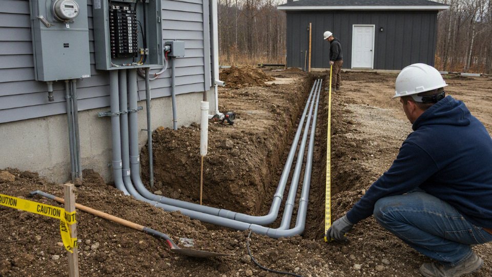
What actually limits the run?
The run is limited first by ampacity and then by voltage drop, with installation conditions deciding how much margin you really have. A 200 amp conductor that is thermally acceptable can still be a poor choice if the far-end voltage sags when the house, shop, pump, welder, or HVAC equipment loads up.
Ampacity is the first gate, not the whole design
Ampacity answers a safety question: can this conductor carry the load without exceeding the permitted insulation and termination temperature? That depends on more than the number “200 amp” printed on the service equipment.
For an underground service or feeder, the engineer or installer has to check:
- Conductor material: copper and aluminum have different resistance and ampacity for the same size.
- Insulation type: common wet-location underground conductors must be rated for the environment, such as conductors listed for wet conduit use where required.
- Termination temperature rating: many practical service calculations are limited by 75°C terminals, even if the conductor insulation has a higher rating.
- Number of current-carrying conductors: more loaded conductors in the same raceway can require derating.
- Raceway arrangement: one conduit in soil is not the same thermal case as several conduits packed together in a duct bank.
- Ambient and soil conditions: dry, compacted, or thermally poor soil holds heat around the raceway longer than damp soil with better heat transfer.
- Local code and utility rules: the utility may specify conductor type, raceway size, meter base requirements, or service lateral details that override a buyer’s preferred cable selection.
The mechanism is simple but often underestimated: current creates heat in the conductor, heat must escape through insulation, conduit, and soil, and the conductor temperature rises until heat generated equals heat dissipated. If the soil or raceway system cannot shed heat well, the same conductor runs hotter at the same load. That is why “underground” is not one condition; it is a family of conditions.
Voltage drop is where long runs usually get expensive
Voltage drop is not usually the first safety limit, but it is often the first performance limit on a long 200 amp run. Resistance in the conductor consumes part of the supply voltage, and the loss rises with current and distance. Longer run, higher current, smaller conductor, warmer conductor: all push the far-end voltage down.
A conductor can be legal for ampacity and still be unsatisfactory for voltage drop. That is the point that catches many projects after trenching is already finished. Lights dim when a compressor starts, motors run hotter, EV chargers reduce output, and controls may trip on undervoltage. In a plant or farm setting, the nuisance symptoms get blamed on the equipment first, when the feeder should have been checked.
For 120/240 V single-phase service, voltage drop hurts quickly because the available voltage is relatively low. A few volts lost on a 240 V load may be tolerable, but the same run feeding 120 V loads sees the percentage loss on half the voltage. Long rural laterals, detached shops, irrigation pumps, and large residential services with electric heat or EV charging deserve a conservative calculation, not a guess from a wire-size chart.
A 200 amp underground conductor sized only for ampacity may still need to be upsized for voltage drop on a long run.True
Ampacity checks thermal safety under the applicable installation conditions, while voltage drop depends on conductor resistance, length, current, and system voltage. These are related but separate design checks.
Service voltage changes the distance sensitivity
For the same power transfer, a higher-voltage three-phase arrangement generally carries less current than a lower-voltage single-phase arrangement. Lower current means less voltage drop and less I²R heating for the same conductor resistance. That is why industrial sites often distribute power at higher voltage and step it down near the load instead of dragging large low-voltage feeders across a property.
A 120/240 V single-phase residence or small shop does not have that luxury unless the utility and equipment arrangement support it. The trade-off is straightforward:
| Arrangement | What it helps | What it complicates |
|---|---|---|
| Larger low-voltage conductors | Simple equipment layout, no transformer near the load | Higher cable cost, larger conduit, harder pulling, larger terminations |
| Higher-voltage distribution with step-down equipment | Lower current over distance, better voltage-drop behavior | Utility approval, transformer cost, protection coordination, more engineering |
| Load relocation closer to service | Shorter feeder, less copper or aluminum | May disrupt site layout, trench routing, equipment access |
For most homes and light commercial buildings, upsizing conductors is the normal remedy. For a factory expansion, pump station, or remote process building, I would at least ask whether the distribution voltage is right before buying a very large low-voltage cable package.
Load diversity decides how often the worst case appears
A 200 amp rating does not mean 200 amps flows every minute. Homes have diversity: the oven, dryer, heat pump, water heater, and EV charger do not always run together. Shops are different. A dust collector, air compressor, welder, kiln, wash line, or process heater can create long-duty current that sits near the design load for hours.
That distinction matters because voltage drop at 65 amps is not the same problem as voltage drop at 180 amps. The cable does not know the nameplate service size; it responds to actual current. Still, design cannot be based on wishful operating habits. If the owner says, “We probably won’t run the charger and the heat at the same time,” I treat that as an operating preference, not an engineering control, unless load management is hard-wired and documented.
Underground installation conditions can change the thermal answer
Underground cable is out of sight, but it is not in a neutral environment. A single PVC conduit in moist native soil behaves differently from a duct bank under asphalt, a direct-buried cable in sand backfill, or several feeders grouped through the same trench. Seasonal changes matter too. In some regions, late-summer dry soil is a worse heat sink than spring soil, even though the trench looked perfect on installation day.
Common conditions that need checking include:
- Direct burial versus conduit: conduit adds a thermal layer but improves mechanical protection and replacement access.
- PVC versus metallic raceway: thermal and grounding behavior differ, and corrosion conditions may drive the choice.
- Duct bank grouping: mutual heating can require derating or larger conductors.
- Burial depth: affects mechanical protection, utility requirements, and sometimes thermal assumptions.
- Wet locations: underground raceways are generally treated as wet inside; conductor insulation must match that reality.
- Pulling length and bends: an electrically correct conductor is still a bad selection if it cannot be pulled without damage.
One mistake I see in procurement packages is treating “larger conductor” as a universal fix. Upsizing for voltage drop does not give permission to downsize grounding or bonding conductors, ignore termination ratings, reduce overcurrent protection, or bypass utility-mandated service equipment. Larger conductors also may not fit standard lugs, meter bases, disconnects, or conduit fill limits without adapters or revised gear.
The practical boundary is this: if the run is short and the load is ordinary, ampacity may dominate and standard service-conductor sizing may be enough after code and utility checks. As the route gets longer, the load becomes more continuous, the soil/raceway condition gets hotter, or the voltage gets lower, voltage drop and installation derating start to control the design and the procurement list changes with it.
Voltage drop sizing method
For a 200 amp underground service, estimate distance by choosing an allowable voltage drop, calculating the actual design current, and applying conductor resistance over the one-way route length. At 240 V single-phase, a conductor that is acceptable at 160 A may be marginal at the full 200 A, so the load assumption can change the cable size before the trench length does.
The basic single-phase voltage drop estimate is:
Voltage drop = 2 × conductor resistance per foot × load current × one-way distance
Where:
Voltage dropis in volts.Conductor resistance per footis in ohms per foot at the expected operating temperature.Load currentis the calculated current, not automatically the breaker rating.One-way distanceis the actual route length from source to load, including risers, sweeps, and equipment offsets.
For three-phase circuits, the common resistance-based estimate is:
Voltage drop = 1.732 × conductor resistance per foot × load current × one-way distance
The one-way distance often confuses people. Current does travel through a complete circuit, but the multiplier accounts for that path. In a single-phase 120/240 V circuit, the 2 × factor represents the outgoing and return conductors. In a balanced three-phase circuit, the geometry of the phase currents is handled by the 1.732 factor, so you still use the one-way route length.
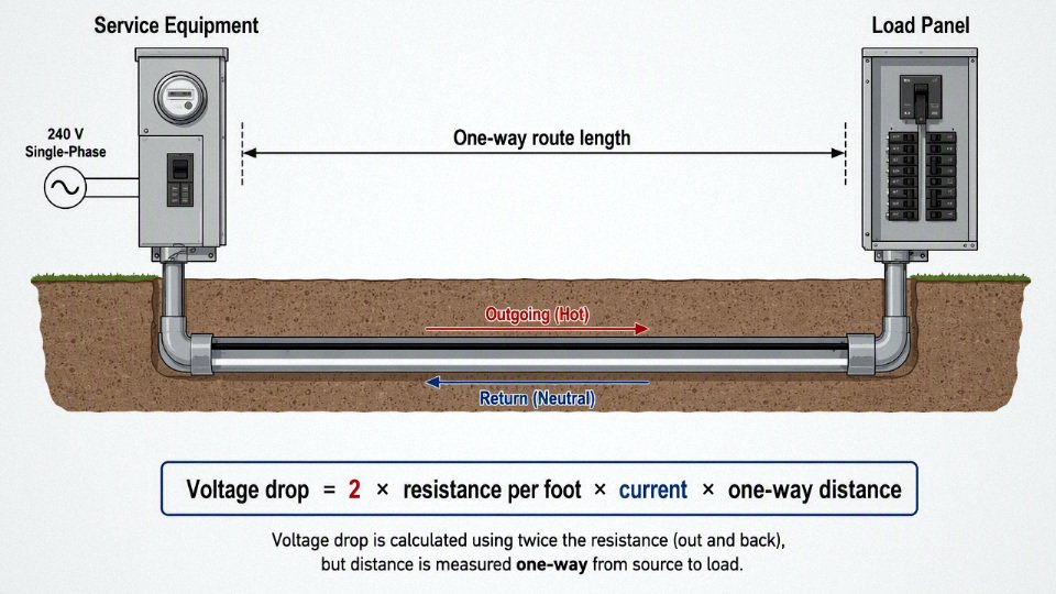
A simple 240 V example shows why a generic distance chart is risky. Assume a 3% voltage drop target on a 240 V single-phase service:
240 V × 3% = 7.2 V allowable drop
Using an approximate resistance for 4/0 aluminum around 0.00010 ohm/ft:
At 200 A:
Voltage drop = 2 × 0.00010 × 200 × distance
Solving for distance:
Distance = 7.2 ÷ 0.04 = 180 ft
At 160 A:
Voltage drop = 2 × 0.00010 × 160 × distance
Distance = 7.2 ÷ 0.032 = 225 ft
Same trench, same cable, same voltage target, but the acceptable distance changes by roughly 45 ft because the design current changed. That is why I get nervous when someone asks for “200 amp wire for 300 feet” without a load calculation. The breaker size is not the voltage drop load by itself.
Approximate benchmarks for common conductors, using rounded resistance values near normal operating temperature, look like this:
| Example conductor | Approx. resistance used for estimating | Approx. one-way distance at 3% drop, 240 V, 200 A | Approx. one-way distance at 3% drop, 240 V, 160 A |
|---|---|---|---|
| 2/0 copper | 0.000097 ohm/ft | about 185 ft | about 230 ft |
| 4/0 aluminum | 0.000100 ohm/ft | about 180 ft | about 225 ft |
| 250 kcmil aluminum | 0.000085 ohm/ft | about 210 ft | about 265 ft |
| 300 kcmil aluminum | 0.000071 ohm/ft | about 255 ft | about 315 ft |
| 350 kcmil aluminum | 0.000061 ohm/ft | about 295 ft | about 370 ft |
These are voltage drop estimates, not automatic code approvals. Ampacity, termination temperature rating, service conductor rules, utility requirements, burial method, conduit fill, and local inspection practice still have to be checked. A 2/0 copper or 4/0 aluminum conductor may be seen in 200 amp residential service work where allowed, but that does not mean it is suitable for every 200 amp underground feeder, commercial service, or continuous-load application.
The mechanism is straightforward: as distance increases, conductor resistance increases in direct proportion, and voltage loss increases with both resistance and current. Upsizing the conductor lowers resistance per foot, which reduces heat and voltage drop, but it also raises cable cost, conduit size, pulling difficulty, termination requirements, and sometimes lead time. The preferred choice flips when the cost of a larger conductor is lower than the cost of nuisance trips, motor heating, light flicker, production interruptions, or later trench rework. In a plant, I would rather buy one size larger before the duct bank is poured than explain later why a compressor starter chatters every hot afternoon.
The 3% and 5% numbers need careful handling. In many projects, designers use 3% as a practical target for a feeder or branch circuit and 5% as a total voltage drop target from service equipment to the final load. Those values are common design recommendations and often appear in specifications, but enforceability depends on the jurisdiction, project documents, and whether the conductors are service conductors, feeders, or branch circuits.
The 3 percent feeder and 5 percent total voltage drop values are common design recommendations, not a universal hard legal maximum for every 200 amp underground service.True
They are widely used for acceptable performance, but the enforceable requirement depends on adopted code language, local amendments, utility rules, and project specifications.
Do not check only the 240 V line-to-line loads. A 200 amp underground service usually supplies plenty of 120 V line-to-neutral loads: lighting, receptacles, control transformers, electronics, garage door operators, irrigation controls, boiler controls, and contactor coils. A voltage loss that looks tolerable as a percentage of 240 V can be twice as severe when judged against 120 V. For example, a 6 V drop is 2.5% at 240 V, but 5% at 120 V.
Neutral sizing also matters. If the neutral is reduced and the load has a heavy line-to-neutral imbalance, the 120 V circuits can see more objectionable voltage variation than the 240 V calculation suggests. This is where a tidy spreadsheet can miss what the maintenance electrician sees: lights dimming when a pump starts, a control relay buzzing, or a PLC power supply logging low-voltage events even though the main breaker never trips.
Motor-starting loads deserve their own check. Pumps, air compressors, HVAC equipment, welders, dust collectors, grain handling equipment, and shop machinery may draw several times running current during starting. A steady-state voltage drop calculation at 160 A or 200 A does not predict the full starting dip unless the motor starting current, power factor, transformer impedance, utility source strength, and conductor impedance are considered.
Typical trouble cases include:
- Deep well pumps and irrigation pumps with long underground runs and across-the-line starting.
- Air compressors that restart under pressure when voltage is already low at the end of the day.
- Welders and plasma cutters with short, high-current demand spikes.
- Large HVAC condensers at rural buildings with weak utility supply.
- EV charging banks where the load is not dramatic at startup but stays high for hours.
- Woodworking, metalworking, or farm shops where several motors may start while lighting and controls are already loaded.
This is where designing only from the nameplate 200 amp service rating can mislead in both directions. For some homes, a full 200 A voltage drop calculation is conservative because the calculated demand may be far below 200 A most of the time. Upsizing the entire underground run based on a load that almost never occurs may waste money, especially if the run is short and the utility transformer is stiff.
The opposite mistake is more expensive. For agricultural loads, process buildings, commercial kitchens, workshops, lift stations, and EV charging, the “actual” demand may stay high for long periods. A casual assumption of 125 A or 160 A may be dangerously optimistic if the equipment schedule shows continuous loads, simultaneous motor operation, or seasonal peaks. Cable temperature rises with sustained current, resistance increases with temperature, and the voltage drop gets worse just when the load is working hardest.
For final sizing, use these inputs rather than a generic distance chart:
- Actual one-way route length
Measure the trench path, not the straight-line distance on a site sketch. Include risers up poles, sweeps into gear, offsets around footings, and routing through handholes. - System voltage and phase
A 120/240 V single-phase service, 120/208 V three-phase service, and 277/480 V three-phase service have different voltage drop percentages for the same conductor loss in volts. Calculated load current
Separate service rating, calculated demand, continuous load, largest motor, and likely simultaneous operation. The right number may not be 200 A.Acceptable voltage drop target
Use the project specification, utility requirement, equipment tolerance, and local inspection expectation. Sensitive controls may justify a tighter target than basic heating loads.Conductor material and size
Copper has lower resistance but higher material cost. Aluminum is common for long underground services because cost per amp-foot is often better, but it needs proper terminations, oxide inhibitor where specified, and torque control.Insulation and temperature rating
Voltage drop calculations should use resistance at the expected operating temperature. Ampacity may be limited by 60°C or 75°C terminals even if the insulation has a 90°C rating.Raceway and installation method
PVC, HDPE, rigid metal conduit, direct burial cable, duct bank grouping, and soil thermal conditions affect ampacity and pulling practicality. They do not all affect voltage drop the same way, but they affect whether the selected conductor can be installed and operated safely.Load character
Motors, welders, chargers, heaters, lighting drivers, and electronics behave differently. A resistive heater tolerates voltage drop differently than a motor starter coil or a compressor motor.
The resistance-only formula is a good first pass for many 200 amp underground services, but it is not the final engineering model for every long run. At longer distances, larger conductors, lower power factor, or three-phase motor loads, AC impedance and voltage drop angle can matter. For those cases, use the cable manufacturer’s impedance data or the applicable electrical design tables, then verify against the equipment manual and local electrical requirements.
Underground cable and conduit choices
For a long 200 amp underground service, the cheapest conductor on a quote sheet is not always the cheapest installed system. Copper buys lower resistance and smaller diameter; aluminum usually wins on weight and material cost in large service sizes. The right choice depends on voltage drop target, termination quality, raceway layout, pulling conditions, and what the utility or electrical authority will accept.
Copper is attractive because it carries the same current with a smaller cross-section than aluminum and has lower resistance, so voltage drop is easier to control over distance. That can reduce conduit fill, make bends less punishing, and leave more margin where the route is already long. The penalty is obvious to anyone who has bought large cable recently: copper ties up more cash, is heavier per amp of capacity, and can make theft risk worse on exposed job sites.
Aluminum is widely used for service entrance conductors because it is lighter and often much more economical in the sizes used for 200 amp feeders and services. The trade-off is that aluminum demands better discipline at terminations. Badly prepared aluminum terminations do not usually fail on day one; they heat, relax, oxidize, and show up later as nuisance voltage problems, browned insulation, or a lug that looks fine until someone opens the gear.
For aluminum underground service conductors, the installation crew needs to control several details:
- Use lugs and terminals marked as compatible with aluminum conductors.
- Apply oxide inhibitor where the terminal manufacturer, utility, or local practice requires it.
- Wire-brush or prepare the conductor only as specified, not by shop folklore.
- Torque every termination with a calibrated torque wrench, not “two hands on a hex key.”
- Recheck accessible terminations during commissioning or scheduled maintenance where permitted.
- Avoid mixing conductor metals, connector types, or strand classes without manufacturer approval.
That last point is where many failures start. A service lateral may be installed perfectly in the trench, then compromised inside the meter base because someone used a lug that was “close enough” or reused hardware from old stock.
Insulation and cable markings matter
Underground service work commonly involves markings such as USE-2, XHHW-2, RHW-2, and THWN-2. These markings are not decoration; they tell you where the conductor is allowed to be installed, its wet-location rating, temperature rating, and whether it is intended for direct burial, raceway use, or specific service entrance applications. The accepted combinations depend on the governing electrical code, utility service rules, and the exact product marking, so the reel tag and printed legend on the cable matter.
Any wet-rated conductor can be used for any underground service installation.False
Wet-location rating alone does not prove the conductor is approved for direct burial, service entrance use, or all raceway configurations. The conductor marking, cable assembly listing, local code, and utility rules must be checked together.
In practice, this is where procurement mistakes get expensive. A buyer may specify “200 amp underground cable” and receive a wet-rated conductor that is fine in conduit but not approved for the planned direct-burial section. Or a direct-burial assembly may be acceptable in the trench but not allowed to continue inside a building or through a particular raceway arrangement without transition to another wiring method. Do not let the purchase order reduce the requirement to ampacity only.
Direct burial versus conduit
Direct burial can reduce raceway material cost and speed up open-trench work, especially on long rural or site-distribution runs. It demands the correct cable construction, proper bedding, warning tape, suitable burial depth, protection where the cable rises out of the ground, and a crew that will not use the trench as a rock dump. Rocky backfill, careless compaction, and later fence-post work are the enemies. The installation can be electrically sound and still have a shortened life because the jacket was damaged before the trench was closed.
Conduit gives better mechanical protection and a practical replacement path, which matters when the service feeds a shop, pump station, cold storage building, or tenant space where downtime is costly. It also introduces its own constraints:
- Conduit fill limits can force a larger raceway than expected.
- Long sweeps, not plumbing elbows, are needed for pullability.
- Heat dissipation may be worse than direct burial depending on arrangement.
- Pulling tension and sidewall pressure must be checked on long routes.
- Water will enter most underground conduit systems eventually, so conductor wet rating still matters.
- Spare conduit may be cheap insurance if the trench is already open.
The trade-off flips when replacement access is worth more than first cost. For a short, protected residential run, direct burial may be sensible if allowed. For a long commercial service under pavement, through landscaped areas, or across property that will be developed later, conduit often saves money the first time a cable must be replaced without excavation.
Long-run procurement and installation constraints
Long 200 amp underground runs are limited by more than ampacity tables and voltage drop math. Conductor size availability can decide the design before engineering preferences do. Large aluminum and copper service conductors may have lead times, minimum order quantities, reel weight limits, and shipping constraints that affect the project schedule.
Before ordering, confirm:
- Total measured route length, including risers, sweeps, gear entry, and service loops.
- Required conductor material and size after voltage drop calculation.
- Insulation type and all printed markings required by code and utility.
- Whether the run is direct burial, conduit, or a mixed installation.
- Maximum reel length available without factory splicing.
- Reel dimensions and weight versus site handling equipment.
- Minimum bending radius for the selected cable.
- Pulling tension limits and whether pulling eyes are needed.
- Sidewall pressure at bends, especially in long PVC or HDPE conduit routes.
- Lubricant compatibility with the cable jacket or insulation.
I have seen otherwise good jobs slowed down because the reel would not fit through the site gate or the electrician had no safe way to lift it off the truck. Those are not engineering failures on paper, but they become schedule failures by Tuesday morning.
Parallel conductors may be considered on larger services or where one very large conductor becomes hard to pull, but they are not a casual workaround for voltage drop or stock shortages. Parallel sets have strict requirements: same material, same size, same insulation, same length, same termination method, and a raceway layout that keeps impedance balanced. Unequal parallel paths can make one conductor carry more current than intended, and that defeats the whole purpose of sharing the load.
For projects involving long cable lengths, overseas shipping, or repeat procurement, manufacturing consistency becomes a practical reliability issue rather than a brochure point. Consistent conductor geometry helps terminations and pulling behavior; insulation quality and sheath integrity matter in wet underground service; testing documentation reduces argument at receiving inspection; export packaging affects whether the reel arrives usable after weeks of handling. Jinda’s role as a cable manufacturer with integrated production, technical support, and export supply capability is relevant in that procurement context: the buyer needs repeatable cable construction, traceable documentation, and packaging suited to the route from factory floor to trench.
Code, utility, and inspection boundaries
A 200 amp underground run is not approved only because the voltage drop math works. The conductor category, the utility service point, the local electrical code, and the inspector’s interpretation all decide what can be installed, where it can terminate, and who is allowed to inspect it before backfill. Do not trench or order long-length cable until the utility and the authority having jurisdiction have agreed on the service arrangement.
The first boundary is terminology. People casually call everything “service cable,” but the code does not treat every underground conductor the same way:
- Service lateral: Usually the underground conductors from the utility system to the service point. In many areas these are utility-owned or utility-controlled, even when the customer provides the trench or conduit.
- Service entrance conductors: Conductors from the service point to the service disconnecting means. These often have tighter rules because they are ahead of the main overcurrent protective device.
- Feeder: Conductors leaving a service disconnect or panel to supply another panel, building, shop, pump house, or detached garage. Feeders normally require an equipment grounding conductor and different neutral-ground handling than service conductors.
- Branch circuit: Conductors from a final overcurrent device to loads such as receptacles, lighting, HVAC equipment, welders, or pumps. A 200 amp underground branch circuit is less common, but the rules are still different from a service lateral.
That classification affects disconnect location, grounding, bonding, conductor identification, neutral isolation, and overcurrent protection. A common field mistake is treating a feeder to a detached building like a service. That can leave the neutral bonded in the wrong place, put return current on metal raceways or grounding paths, and create nuisance voltage on equipment frames. It may work electrically on day one, but it will not necessarily pass inspection, and it is not a harmless paperwork issue.
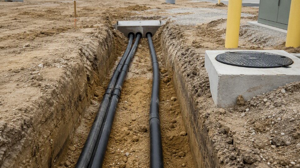
Utility requirements are a separate layer. The utility may not accept the conductor size or routing that looks best to the owner’s electrician. Depending on the territory, they may dictate:
- Meter location and height
- Service point location
- Whether the customer or utility supplies the lateral conductors
- Conduit material, trade size, and number of bends
- Minimum sweep radius for pulling service cable
- Trench route and separation from gas, water, communications, or drainage
- Pull box or handhole requirements on long runs
- Inspection sequence before energizing
- Whether the trench must remain open for utility inspection
This is where procurement gets expensive fast. Ordering 300 ft of large aluminum conductors before the utility confirms conduit size and service point is gambling with freight, restocking, and schedule. I have seen perfectly good cable become the wrong cable because the utility moved the meter-main from a pole line to the building wall, changing what counted as service entrance versus feeder length.
Burial depth is another approval item, not just an installation preference. Required cover depends on wiring method, voltage, physical protection, residential or commercial location, and whether the route crosses driveways, parking areas, farm lanes, or industrial traffic zones. Local amendments can be stricter than the base electrical code. A residential yard run in PVC is not the same condition as a commercial service crossing a forklift yard or truck approach. If the site has frost heave, rocky backfill, or future paving planned, the installation detail matters as much as the number printed in a table.
Grounding and bonding need special attention at the transition between service equipment and feeder equipment. The design must correctly identify:
- Grounded conductor: Usually the neutral in a 120/240 V single-phase system.
- Equipment grounding conductor: The fault-current path on the load side of the service disconnect.
- Grounding electrode conductor: The conductor connecting service or building grounding equipment to grounding electrodes.
- Bonding jumpers: Connections that intentionally bond metal raceways, enclosures, and service equipment.
- Neutral isolation: Required in feeder-fed panels so neutral current stays off equipment grounding paths.
For a detached structure, the feeder panel typically needs isolated neutrals, an equipment grounding conductor back with the feeder, and grounding electrodes at the detached building, subject to the adopted code and local inspection practice. The mechanism is simple: fault current must have a low-impedance metallic return path to trip the breaker quickly, while normal neutral current must not use that same equipment path. Mixing those functions creates objectionable current on raceways, building steel, water piping, or cable armor.
Service equipment and feeder equipment can also trigger different device requirements. Depending on the jurisdiction and adopted code edition, the project may need service disconnects, emergency disconnects for dwellings, surge protective devices, specific labeling, grouped disconnects, and working clearance in front of equipment. Commercial sites may add utility CT cabinets, sealable sections, bollards, or dedicated meter rooms. None of that is solved by upsizing wire.
Temperature rating is a quieter compliance trap. Large underground conductors may have insulation marked for 90°C wet locations, but the connected equipment lugs often limit ampacity selection to the 75°C column for conductors in this size range. The 90°C rating may still be useful for adjustment or correction calculations where allowed, but it does not automatically let the installer use the 90°C ampacity as the final conductor ampacity.
A conductor with 90°C insulation can always be sized using the 90°C ampacity if it is underground.False
Final ampacity is limited by the temperature rating of terminations and equipment, commonly 75°C for large service and feeder conductors. The applicable code edition and equipment markings must be checked.
The trade-off is schedule versus certainty. Early cable purchasing may protect a production slot on a long reel, but underground 200 amp work has too many approval-dependent variables to buy on assumption alone. The safer procurement sequence is to confirm the service category, utility drawings, burial method, conductor material, insulation type, raceway size, grounding scheme, and inspection hold points first; then release cable and conduit with enough detail that the installer, inspector, and utility are all looking at the same installation.
Installation risks that change distance
A 200 amp underground run that looks acceptable by voltage drop can still be a bad installation if the field conditions reduce ampacity, damage the cable during pulling, or create wet-location failures later. Distance is not just an electrical calculation; it is also a heat, moisture, conduit, and workmanship problem, especially once the route gets long enough that pulling and termination quality become marginal.
Soil is the first place paper designs get too optimistic. Underground conductors reject heat through the insulation, raceway, backfill, and surrounding soil. Damp, uniform soil usually carries heat away better than dry rocky fill, compacted spoil full of air pockets, or high thermal-resistivity material. If a trench is backfilled with random excavated rubble instead of suitable thermal backfill, the conductor can run hotter at the same load. That does not always mean the service fails immediately; it means insulation aging accelerates, ampacity assumptions become weaker, and the safety margin behind a long-distance design gets thinner.
Raceway grouping can create the same problem from the other side. One 200 amp lateral in one conduit is different from several loaded conduits packed into a duct bank or sharing the same trench for a long distance. Adjacent circuits warm the soil and each other, so conductor cooling is reduced. Depending on the applicable code, raceway arrangement, load diversity, and installation details, derating or an engineered ampacity calculation may be required. The practical trap is treating a single-conduit voltage drop estimate as if it still applies after the service is placed beside other loaded feeders.
Underground raceways should be assumed to contain water during their service life.True
This is standard electrical installation practice. Even well-glued or gasketed underground raceways can accumulate condensation, groundwater, or water from box entries, so conductors and fittings must be suitable for wet locations.
Long pulls add mechanical risk that no voltage drop spreadsheet sees. Before energizing, the cable may already be compromised by:
- excessive pulling tension on a long straight section;
- too many bends between pull points;
- tight sweeps that violate minimum bending radius;
- crushed, ovalized, or poorly joined conduit;
- dried mud, gravel, or duct burrs inside the raceway;
- inadequate pulling lubricant or the wrong lubricant for the jacket and insulation;
- pulling by one conductor instead of using an approved pulling head or basket grip.
This is where upsizing can work against the installer. A larger copper or aluminum conductor may reduce voltage drop, but it also increases cable stiffness, pulling tension, bend radius, conduit fill, and the physical size of lugs and termination compartments. In practice, the preferred choice can flip: instead of simply increasing conductor size again, it may be better to revise the route, add compliant pull points, increase conduit size, change to parallel conductors where permitted and properly designed, or move service equipment closer to the load.
Water exposure needs the same respect. Underground raceways are wet locations, not “mostly dry” spaces. Conductors must have wet-location insulation suitable for the installation, and any splice, termination, pull box, handhole, meter enclosure, or service equipment connection must match that environment. Splices in long service runs should be avoided where possible; every splice adds resistance, workmanship dependency, and a future failure point. Where a splice is unavoidable, use an approved underground-rated splice kit, place it only where allowed and accessible when required, and install it exactly as the kit instructions specify. A half-cleaned aluminum conductor, a rushed torque step, or a poorly sealed kit can become the weak point years before the conductor itself is worn out.
Voltage drop can also drift worse over time. Loose terminations increase contact resistance. Aluminum connections can oxidize if not prepared and protected correctly. Damaged strands reduce effective conductor area. Moisture entering a termination space can drive corrosion and heating. The customer sees dimming lights or nuisance equipment behavior and assumes the original conductor was undersized, but sometimes the real fault is a joint that has been cooking quietly since commissioning.
The safe distance estimate holds only while the installation conditions match the assumptions: soil thermal performance, raceway layout, wet-location components, pull geometry, splice quality, and termination integrity. Once any of those are uncertain, the next useful step is not another decimal place in the voltage drop calculation; it is a route review with conduit layout, pull points, conductor construction, and termination hardware checked together.
Cost tradeoffs beyond larger wire
A long 200 amp underground run is not automatically solved by buying the next bigger conductor. Once the route gets long, the economical answer may be a different equipment location, a revised load layout, a different service arrangement, or a standard cable size that is easier to buy and install. The cheapest design is usually the one that minimizes installed system cost, not conductor cost alone.
Upsizing affects more than the copper or aluminum invoice. In the field, a larger conductor often drags several other costs behind it:
- Conductor price: Copper rises fast with cross-sectional area; aluminum is usually cheaper per ampacity but larger and less flexible.
- Conduit size: Larger conductors may push the raceway into the next trade size because of fill limits and pulling practicality.
- Trench width and bedding: A bigger conduit bank, separation requirements, warning tape, sand bedding, and backfill handling can change excavation cost.
- Sweeps and pull boxes: Long-radius bends, larger handholes, and intermediate pull points may be needed to keep pulling tension and sidewall pressure under control.
- Termination hardware: Larger lugs, reducers, compression tools, oxide inhibitor for aluminum, heat-shrink kits, and enclosure space all matter.
- Freight and reel handling: Big reels are not handled like cartons. Forklift capacity, unloading space, reel stands, and damage risk become part of the job.
- Labor: Pulling oversized cable through a wet trench on a Friday afternoon is where “only one size larger” becomes two extra electricians and a tugger.
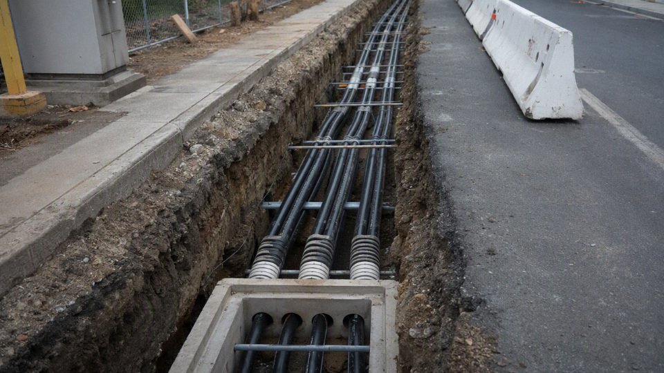
For a remote house, pump station, shop, or guard building, moving the meter, transformer, service disconnect, or load center can be cheaper than carrying 200 amps a long distance at low voltage. Utility rules decide what is allowed, but the economic logic is simple: shorten the high-current, low-voltage portion of the run. A pad-mounted transformer placed closer to the load, for example, may cost more in utility coordination but save a painful amount in secondary conductors, trench complexity, and voltage-drop mitigation.
Do not assume the load truly needs a full 200 amp feeder at the far end. If the calculated demand is lower, a smaller feeder to a subpanel may be acceptable, subject to code, future expansion, and inspection approval. On farms, small factories, and commercial yards, distributing loads can also help: put motor loads near the supply, split lighting and receptacles separately, or serve a remote machine building with a properly sized feeder instead of dragging the entire service capacity across the site.
Where the utility and equipment allow it, higher voltage or three-phase service changes the math. For the same power, higher voltage means lower current, and lower current reduces voltage drop and conductor heating. That can make a 480 V three-phase distribution approach more economical than a very large 240 V single-phase run, especially for motor-heavy industrial loads. The tradeoff is extra equipment cost, transformer selection, protection coordination, arc-flash considerations, and personnel skill requirements.
For the same delivered power, increasing distribution voltage reduces current and therefore reduces voltage drop in the conductors, assuming conductor resistance and route length are unchanged.True
Voltage drop is proportional to current for a given conductor impedance. Higher-voltage distribution can reduce current for the same power, but the final design still depends on load type, power factor, equipment ratings, code rules, and utility availability.
Lifecycle cost should stay in the calculation. Excessive voltage drop increases conductor losses, can run motors hotter, worsens starting performance, and causes nuisance issues with welders, compressors, HVAC equipment, EV chargers, and electronic controls. A conductor that “passes inspection” but leaves equipment struggling at the far end may cost more through downtime and shortened equipment life than the next practical size up.
Procurement can flip the decision too. A theoretically perfect conductor size is not always the best buy if it is nonstandard, delayed, hard to document, or requires uncommon terminations. For international or bulk cable purchasing, standard sizes, available insulation types, reel lengths, test documentation, and supplier production schedules can outweigh a small optimization on paper. The design stops being purely electrical once the cable has to be manufactured, shipped, pulled, terminated, inspected, and maintained.
Procurement data for cable quotes
A usable cable quote needs more than “200 amp underground, 180 feet.” The supplier has to know the electrical system, installed route, load behavior, installation method, governing standards, and jobsite exposure before conductor size, insulation, reel length, packaging, and documentation can be priced correctly. Bad input usually shows up later as short reels, wrong markings, failed inspection, or expensive field splices.
For a 200 amp underground service package, send the quote request as a technical schedule, not a casual material list:
- Complete route length
- Straight-line trench distance is not enough.
- Include:
- Vertical risers at meter, transformer, switchgear, or panel
- Sweeps and offsets
- Termination slack
- Service loops required by the utility or contractor
- Pulling waste and cutting allowance
- Reasonable contingency, often a few percent depending on route uncertainty
- If the route is not field-staked yet, say so. A supplier can quote reel lengths with tolerance, but they cannot guess whether the trench crew will add 25 feet around a driveway, retaining wall, or gas line conflict.
- System configuration
- State whether the service is:
- 120/240 V single phase
- 208Y/120 V three phase
- 480Y/277 V three phase
- Another voltage or grounding arrangement
- This changes conductor count, neutral treatment, voltage drop calculation, insulation selection, and sometimes utility acceptance.
- Load and voltage-drop basis
- Provide:
- Calculated load in amperes or kVA
- Continuous load percentage
- Acceptable voltage drop
- Motor starting or compressor starting loads
- Future expansion allowance
- In practice, this is where many “200 amp” quotes split into different answers. A lightly loaded farm shop, a house with heat pumps, and a small process building with motors may all have a 200 amp service rating, but the cable decision is not the same.
- Conductor schedule
- Confirm:
- Copper or aluminum
- Conductor size
- Number of phase conductors
- Neutral size, full or reduced where permitted
- Equipment grounding conductor requirements
- Whether parallel conductors are being considered
- Parallel runs can reduce pulling difficulty and manage large sizes, but they add termination discipline, raceway fill checks, phase grouping requirements, and more chances for installation error.
- Installation method
- Identify the actual route type:
- Direct burial
- PVC conduit
- HDPE conduit
- Rigid metal conduit risers
- Concrete duct bank
- Tray transition
- Mixed underground and aboveground sections
- Cable that is acceptable in one method may be wrong, uneconomical, or noncompliant in another.
Also list the required cable standards, insulation markings, wet-location rating, flame rating where relevant, certification documents, factory test reports, packaging method, reel dimensions, lifting limits, and export documentation. For international projects, reel size is not a clerical detail; it affects container loading, crane access, site storage, and whether the contractor can pull the cable without respooling it in the mud beside the trench.
Site conditions belong in the request too: soil type, ambient temperature, trench drainage, corrosive exposure, rodent risk, flood history, and local utility rules. Shandong Jinda Special Cable Group’s integrated R&D, production, sales, technical support, and after-sales structure is useful on larger or repeat cable orders because the same specification can be carried from engineering review into production control, documentation, packing, and later project support. The boundary is simple: the supplier can quote accurately from complete project data, but final approval still has to match the current code, utility requirements, and the engineer of record’s design.
Frequently asked questions
Can I run 200 amp service 300 ft underground?
Yes, but 300 ft is long enough that voltage drop and installation cost usually drive the design, not just ampacity. A standard minimum-size 200 amp conductor may be electrically legal in some cases, yet still give poor voltage at the far end under heavy load. Expect conductor upsizing, a load calculation, and utility coordination.
What wire size is needed for 200 amps at 200 ft?
There is no responsible one-size answer without knowing conductor material, allowable voltage drop, load profile, raceway type, temperature conditions, and whether this is service entrance or feeder wiring. In practice, 200 ft often pushes buyers beyond the smallest code-ampacity conductor, especially with aluminum. Have the electrician or engineer calculate voltage drop using the expected demand load, not just catalog ampacity.
Is 4/0 aluminum enough for a 200 amp underground service?
4/0 aluminum is commonly associated with 200 amp residential service conductors, but “enough” depends on the route length, local code rules, utility requirements, and voltage drop tolerance. For a short service lateral it may be accepted. For a few hundred feet, it may still carry the current but deliver more voltage drop than the owner wants.
Is copper always better than aluminum for long runs?
Copper has lower resistance, so it usually gives less voltage drop for the same conductor size. That does not automatically make it the best purchase. Aluminum is lighter and often cheaper per amp-foot, so upsized aluminum can beat copper economically on long underground runs. The decision flips when conduit space, terminations, pulling tension, or project standards favor copper.
Does the electrical code set a maximum distance for underground service?
Electrical codes generally do not give a simple maximum distance for a 200 amp underground service. They regulate ampacity, burial method, grounding, protection from damage, working clearances, and approved wiring methods. Voltage drop is often treated as a design recommendation rather than a hard pass/fail rule, but utilities and inspectors can still impose project-specific requirements.
Should I calculate voltage drop at 200 amps or my actual load?
Use the calculated or expected load for design judgment, and check worst-case scenarios where needed. Designing strictly at 200 amps can oversize the cable for a house that rarely draws that much. Ignoring high simultaneous loads can create nuisance low-voltage problems when HVAC, pumps, welders, or EV charging overlap.
Can I use direct-burial cable instead of conduit?
Sometimes, if the cable type is listed for direct burial and the installation meets burial depth, protection, marking, and local inspection requirements. Conduit gives better mechanical protection and makes route transitions cleaner, but it can add pulling difficulty on long runs. I usually prefer conduit where future replacement or driveway crossings are a concern.
Do I need a ground wire to a detached building?
For a feeder to a detached building, modern practice typically requires an equipment grounding conductor run with the feeder, plus grounding electrodes at the detached structure as required by code. Do not rely on earth as the fault path. Neutral-ground bonding rules also matter; this is one area where older farm wiring habits cause trouble.
Can I splice a 200 amp underground service cable?
Yes, but only with splice kits and enclosures rated for the conductor material, insulation type, voltage, burial environment, and installation method. A buried splice is not the place for hardware-store improvisation. Poor compression, wrong inhibitor on aluminum, or a cheap moisture seal can become a failure that costs a trenching crew to find.
Who decides the final conductor size: electrician, utility, engineer, or inspector?
The final answer is shared. The electrician usually sizes and installs the conductors, the utility controls service connection requirements, the inspector enforces adopted code, and an engineer may be needed for long runs, commercial loads, or unusual site conditions. For procurement, get those requirements settled before ordering cable; returning cut-to-length service conductors is rarely pleasant.
Verify your 200 amp route
A 200 amp underground service is not approved by asking, “How far can it run?” The practical decision is whether the selected conductor can carry the calculated load, keep voltage drop within the project target, satisfy the utility and inspector, and survive installation over the actual trench route. Miss any one of those, and the distance number is just a guess with expensive copper or aluminum attached to it.
Before trenching or ordering a long pull, lock down the engineering and purchasing data as a single package:
- One-way route length: measure the actual conductor path, not the straight-line distance across the yard or site plan.
- Service voltage and phase: for example, 120/240 V single phase or a three-phase service arrangement.
- Calculated load: use a proper load calculation, not only the main breaker size.
- Voltage drop target: commonly selected by the designer or owner based on equipment sensitivity and acceptable performance.
- Conductor material: copper or aluminum, including the intended size and number of conductors.
- Insulation and cable type: suitable for wet underground locations and the selected raceway or direct-burial method.
- Installation method: conduit, duct bank, direct burial, sweep bends, pulling boxes, and expected pulling distance.
- Utility requirements: service point, meter base location, service lateral rules, allowed conductor types, and who supplies which part.
- Burial condition: soil, rock, groundwater, paving, frost depth, traffic loading, and any crossing under drives or process areas.
- Termination equipment: lugs, meter socket, disconnect, panel, transformer, and whether they are rated for the selected conductor material and size.
Use a licensed electrical designer or qualified electrician to perform the load calculation and voltage drop check before the trench is opened. In practice, I would also confirm the inspection sequence before buying cable: some jurisdictions want conduit inspected before backfill, some utilities will not energize until meter location and service entrance details match their drawing, and a late change can leave you with hundreds of feet of the wrong conductor on a reel.
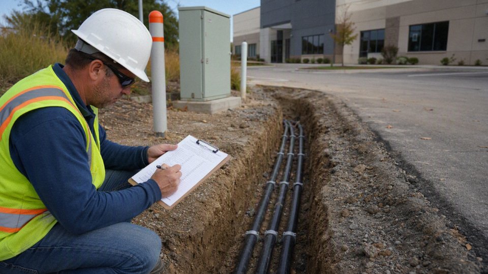
For cable selection and project quotation, provide Jinda with the route length, system voltage, load data, preferred conductor material, installation method, applicable documentation requirements, and any utility specification you have received. Jinda can use that information to support technical cable selection and prepare a project quotation for the underground service cable package.