Undersizing a 100 amp underground feeder is not a small paperwork mistake; it shows up later as voltage drop, nuisance heating, failed inspections, or a trench that has to be reopened after landscaping and paving are finished. That turns a simple service run into labor, downtime, rework, and wasted cable cost. The right starting point is to size the conductors from ampacity, installation conditions, terminal ratings, and the rule set your inspector will enforce.
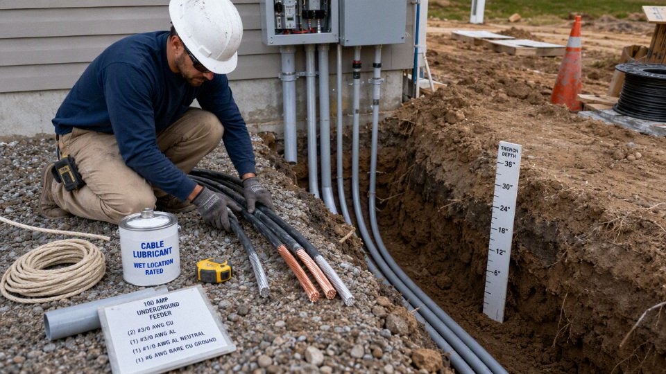
For a typical 100 amp underground feeder, start with 3 AWG copper or 1 AWG aluminum conductors based on 75°C ampacity, subject to local code and equipment terminals. In some dwelling applications, 4 AWG copper or 2 AWG aluminum may be allowed, and the equipment grounding conductor is commonly 8 AWG copper or 6 AWG aluminum.
The catch is that “100 amp underground wire” is not one decision. Conduit fill, direct burial cable type, voltage drop on long runs, aluminum terminations, wet-location ratings, and whether this is a dwelling service, feeder, garage supply, pump house, or shop panel can all change the correct purchase. That is where many jobs go wrong: the wire size is chosen before the installation is understood.
Code rules that control size
For a 100 amp underground run, the code answer is not one wire size until the installation conditions are known. The usual NEC-style sizing path starts with ampacity tables, then applies material, insulation rating, terminal temperature, ambient correction, conductor count, continuous-load rules, installation method, and voltage-drop judgment before anyone should write a purchase spec.
That is why one reputable source may say 3 AWG copper or 1 AWG aluminum, while another residential example shows 4 AWG copper or 2 AWG aluminum. They may both be correct inside their own assumptions, and wrong if copied into the wrong job.
The variables that actually control the conductor size
The conductors are not sized only by the breaker handle saying “100 A.” A competent design or inspection review normally checks these items:
- Conductor material: Copper and aluminum have different ampacity, termination preparation, bend radius, weight, price, and availability. Aluminum is common for long feeders because cost per amp-foot is attractive, but terminations need the right lugs, oxide inhibitor where specified, and proper torque.
- Insulation temperature rating: Common building-wire insulation may be rated 75 degrees Celsius or 90 degrees Celsius, depending on the conductor type. Underground cable assemblies and wet-location conductors must also be suitable for the environment.
- Terminal temperature rating: The breaker, disconnect, meter base, panel lugs, and splice connectors may limit the usable ampacity. For larger conductors, 75 degrees Celsius terminals are common, but the actual marking on the equipment wins.
- Ambient temperature: Underground raceways are not exposed to attic heat, but outdoor terminations, pull boxes, and above-grade sections can see higher ambient temperatures. Correction may be required depending on the code method used.
- Number of current-carrying conductors: More loaded conductors in the same raceway or cable can trap heat. A typical single-phase feeder has two ungrounded conductors plus a neutral that may or may not count fully, depending on the load type and code rules.
- Continuous load: Loads expected to run for three hours or more may require sizing at 125 percent of the continuous load unless a specific rule or listed equipment instruction allows another method.
- Installation method: Direct-burial cable, individual conductors in PVC conduit, rigid metal conduit, cable in duct bank, and conductors entering equipment each create different mechanical and thermal conditions.
- Overcurrent protective device: The breaker or fuse rating drives both conductor protection and equipment grounding conductor sizing. A 100 amp breaker is not just a convenient switch; it is part of the conductor protection system.
In practice, the two details most often missed in informal sizing advice are terminal temperature and conductor adjustment. A wire with 90 degrees Celsius insulation does not automatically get to use the 90 degrees Celsius ampacity as its final allowable ampacity if it lands on 75 degrees Celsius equipment.
How the ampacity table is used
Standard conductor sizes are selected from ampacity tables by material, insulation temperature, and conductor size. Under common NEC-based practice, a straightforward 100 amp underground feeder often lands around 3 AWG copper or 1 AWG aluminum when using the 75 degrees Celsius ampacity basis, assuming the connected equipment is rated for that temperature and no other derating pushes the conductor larger.
The mechanism is heat. Current produces I²R losses in the conductor. That heat has to leave through insulation, conduit fill, soil, air spaces, equipment terminals, and enclosure surfaces. If the insulation can tolerate more heat than the lug, the lug becomes the weak link. If several current-carrying conductors are packed in the same raceway, the thermal environment gets worse before the breaker ever trips.
The temperature columns serve different jobs:
| Ampacity column | What it usually means in design | Common trap |
|---|---|---|
| 60 degrees Celsius | Often applies to smaller conductors or equipment marked only for 60 degrees Celsius use | Using a 75 degrees Celsius size where the equipment only permits 60 degrees Celsius termination ampacity |
| 75 degrees Celsius | Common basis for larger conductors on equipment with 75 degrees Celsius rated terminals | Assuming the conductor is acceptable without checking every termination in the run |
| 90 degrees Celsius | Often used for adjustment or correction calculations when insulation is rated for it | Treating the corrected 90 degrees Celsius value as final even though the terminal is rated lower |
A conductor with 90 degrees Celsius insulation can always be sized from the 90 degrees Celsius ampacity column for a 100 amp feeder.False
The 90 degrees Celsius column may be used for adjustment or correction when allowed, but the final usable ampacity is still limited by the equipment termination rating, conductor material, installation conditions, and applicable code rules.
A common field example: THHN/THWN-2 copper conductors may have a 90 degrees Celsius insulation rating, but the breaker lugs in the panel may be marked 75 degrees Celsius. The designer may start with the 90 degrees Celsius column to apply adjustment factors, then confirm the final adjusted ampacity does not exceed what is allowed at the 75 degrees Celsius termination. That is the kind of detail that separates a clean inspection from a red tag and a rushed material reorder.
Why residential examples may show smaller conductors
The dwelling-service and dwelling-feeder allowance is the reason residential charts sometimes show 4 AWG copper or 2 AWG aluminum for 100 amp applications. Under certain NEC dwelling rules, service or feeder conductors supplying a dwelling may be allowed to be smaller than the general ampacity table result because of load diversity assumptions built into the code.
That allowance is not a blank check. It does not automatically apply to every 100 amp circuit with a house nearby, and it should not be casually carried over to:
- Detached workshops with welders, compressors, kilns, or dust collection
- Pump stations, irrigation controls, or farm service equipment
- Commercial tenant panels
- EV charging panels unless the applicable rules and equipment instructions support it
- Detached garages with mixed future loads
- Industrial control panels or machine feeders
- Any feeder where the local authority does not accept the dwelling allowance for that configuration
The trade-off is simple enough: the dwelling rule can reduce copper or aluminum cost on eligible residential work, but it reduces margin for non-diversified or future heavy loads. In a procurement setting, that saving can disappear fast if the inspector rejects the interpretation after the cable is already pulled through 120 feet of underground conduit.
Continuous load can push the design above 100 amps
A 100 amp breaker does not mean the circuit can feed 100 amps of continuous load without further checking. If the expected load runs for three hours or more, many code applications require the branch circuit or feeder rating to be at least 125 percent of the continuous load, unless a specific code rule or listed equipment instruction says otherwise.
For example, a steady 80 amp continuous load may need equipment and conductors suitable for 100 amps after the 125 percent calculation. A steady 100 amp continuous load may require a larger circuit, not just “100 amp wire.” This matters for EV charging, process heaters, ventilation loads, pumps, grow facilities, battery equipment, and some commercial lighting or HVAC combinations.
This is a commercial issue as much as an electrical one. If the buyer only says “100 amp underground cable” but the load schedule shows a nearly continuous 92 amp draw, the quoted cable may be technically underspecified. The right purchase inquiry should include load type, duty cycle, voltage, phase, overcurrent device, and whether the run supplies a dwelling service, feeder, subpanel, or dedicated equipment.
Voltage drop is a performance limit, not usually an ampacity limit
Voltage drop normally does not decide whether the conductor is protected from overheating. Ampacity does that. Voltage drop decides whether the equipment at the far end receives acceptable voltage during running and starting conditions.
Long underground runs are where this becomes expensive. A conductor that is code-legal for ampacity may still give poor motor starting, nuisance trips, dim lights, low heater output, or unhappy electronics at the load end. The estimate depends on:
- One-way circuit length
- Voltage and phase
- Load current and duty cycle
- Copper versus aluminum
- Power factor for motor loads
- Starting current, not only running current
- Acceptable voltage drop target for the equipment
- Whether the load is steady, cyclic, or intermittent
Upsizing from aluminum to larger aluminum is often cheaper than switching to copper on long runs, but not always. Conduit size, pulling tension, bend count, lug capacity, splice kits, and availability can flip the decision. I have seen jobs where the cable price was not the constraint; the problem was that the larger conductor would not land in the existing disconnect without adapter lugs and enclosure changes.
Neutral and grounding conductor sizing
The neutral is not always required to be the same size as the ungrounded conductors if a proper load calculation shows the neutral load is lower. That said, many practical 100 amp feeders use a full-size neutral because it keeps the installation simpler to inspect, easier to explain, and more flexible if the owner later adds 120 V loads.
Reasons a full-size neutral is often chosen include:
- Mixed 120/240 V residential or light commercial loads
- Future panel changes that are not fully known
- Simpler cable purchasing and inventory control
- Fewer arguments during inspection
- Reduced risk from load imbalance assumptions that prove optimistic later
The equipment grounding conductor is different. It is not sized from the normal load current in the same way as the phase conductors. For a 100 amp feeder, a common size is 8 AWG copper or 6 AWG aluminum, subject to the overcurrent protective device rating, local code, and the wiring method.
The advanced detail that gets missed: if the ungrounded conductors are increased for voltage drop, common code rules may require the equipment grounding conductor to be increased proportionally. The logic is fault clearing. A longer or larger phase conductor changes the impedance relationship in the fault path, and the grounding conductor still has to carry fault current long enough and strongly enough to help trip the breaker. So a long 100 amp feeder upsized for voltage drop may not be complete if only the hot conductors were upsized and the grounding conductor stayed at the minimum table size.
This is where informal online answers are weakest. They usually answer the easy ampacity question and skip the installation-specific corrections, dwelling-rule boundary, neutral calculation, and grounding conductor adjustment. For procurement, the safer specification is not just “100 amp underground wire,” but a conductor schedule tied to code basis, run length, wiring method, terminal ratings, load calculation, and inspection jurisdiction.
Copper versus aluminum conductors
For a typical 100 amp underground feeder sized from standard 75°C ampacity rules, the usual comparison is 3 AWG copper versus 1 AWG aluminum. Where the NEC dwelling allowance is valid and accepted by the local authority, that may shift to 4 AWG copper versus 2 AWG aluminum. The better choice is rarely just “copper is best” or “aluminum is cheaper”; it depends on run length, conduit, terminations, inspection risk, and procurement scale.
Copper conducts better than aluminum, so it carries the same current in a smaller conductor. That smaller diameter can matter underground because the wire is not just an electrical item; it has to fit through conduit, survive pulling tension, land cleanly in lugs, and leave enough room in gear that may already be crowded with neutral bars, bonding jumpers, and branch circuit wiring.
A practical comparison looks like this:
| Selection point | Copper option | Aluminum option | What changes in the field |
|---|---|---|---|
| Typical standard 100 amp feeder size | 3 AWG copper | 1 AWG aluminum | Aluminum is larger for similar ampacity, so conduit fill and pulling effort need checking. |
| Possible dwelling-rule size, where permitted | 4 AWG copper | 2 AWG aluminum | Only use this where the dwelling allowance applies and the inspector accepts it for the specific service or feeder. |
| Conductivity and resistance | Lower resistance at a given ampacity size | Higher resistance unless upsized | Copper often helps on voltage drop; aluminum can be upsized economically on long runs. |
| Material cost | Higher conductor cost | Usually lower conductor cost | Aluminum often wins on long underground feeders and bulk buying. |
| Termination sensitivity | More forgiving | More dependent on correct lug, prep, and torque | Aluminum workmanship errors show up later as heat, nuisance trips, or failed inspections. |
| Space and handling | Smaller but heavier | Larger but lighter | Copper may reduce conduit size; aluminum may be easier to handle per metre or foot but needs more space. |
The electrical mechanism is straightforward. Resistance creates voltage drop and heat in proportion to current and conductor length, so a 100 amp feeder that looks fine at 40 ft can become a different decision at 180 ft, especially with motors, compressors, welders, HVAC equipment, or shop loads with high starting current. Copper’s higher conductivity gives it an advantage when comparing common ampacity sizes, but aluminum lets a buyer step up one size without the same material-cost penalty. On long underground runs, upsized aluminum can be the lowest-cost way to control voltage drop while still meeting ampacity requirements.
That statement has a boundary: it stops holding when the larger aluminum conductor forces a larger conduit, difficult bends, more expensive terminations, or a failed fit in the equipment lugs. I have seen jobs where the cable price looked good on the purchase order, then the installer had to change from a comfortable pull to a fight through two 90-degree bends and a weathered PVC sweep that should have been replaced. The copper alternative would have cost more per foot, but the crew would have finished faster and with less risk of damaged insulation.
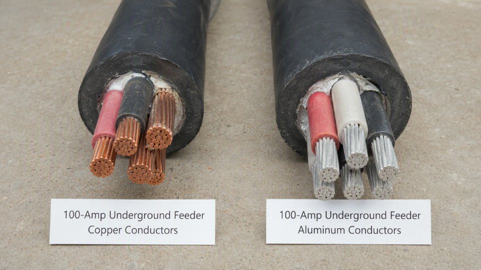
Mechanical behavior is where plant and site crews feel the difference. Copper is not magic, but it tolerates rough handling better. Aluminum is softer, forms oxide on the surface, and depends heavily on the termination system being correct:
- Use lugs listed or marked for aluminum conductors, or dual-rated copper/aluminum lugs where appropriate.
- Clean and prepare the conductor as required by the equipment or connector manufacturer.
- Apply oxide inhibitor only where specified or permitted; do not treat it as a universal cure.
- Torque terminals with a calibrated torque tool, not a “good feel” from a tired wrist at 5 p.m.
- Re-check whether the equipment terminal temperature rating is 60°C or 75°C before applying ampacity tables.
- Confirm bend radius and pulling tension limits from the cable supplier, especially for compact stranded conductors or assemblies with an overall jacket.
Copper also needs proper torque and listed terminals, but it is less sensitive to surface oxide and creep-related connection problems. Aluminum connections can perform perfectly for decades when installed correctly; they become troublesome when someone treats them like oversized copper and skips the connector details. In outdoor pedestals, meter-main equipment, farm services, pump houses, and coastal installations, that workmanship margin matters.
Corrosion and wet-location design should not be simplified to “copper good, aluminum bad.” Underground raceways are considered wet locations in many code contexts, and water eventually finds its way into most underground conduit systems through condensation, imperfect seals, or grade movement. Both metals need insulation rated for the environment, such as the appropriate wet-location-rated conductor or cable assembly for the installation method. The difference is that aluminum terminations deserve closer attention wherever damp air, fertilizer dust, salt exposure, or service-equipment condensation is present.
For procurement, the metal choice should be tied to a complete cable specification, not just “100 amp underground wire.” International buyers should define:
- Conductor material: bare or metal-coated copper, or aluminum alloy as required by the project.
- Standard basis: ASTM, IEC, UL, CSA, or a project-specific specification.
- Conductor construction: stranded class, compact stranded or concentric stranded, and flexibility requirements.
- Insulation compound and rating: for example, wet-location suitability, voltage rating, temperature rating, sunlight resistance where exposed, and direct-burial rating if not in conduit.
- Cable assembly details: single conductors in conduit versus multi-core cable, grounding conductor inclusion, jacket type, color coding, and phase identification.
- Marking language: English markings, project codes, meter or foot marks, voltage class, conductor size, and certification marks where applicable.
- Documentation: routine test reports, factory test records, packing lists, drum schedules, certificates of conformity, and any third-party inspection required by the buyer.
For standard 75°C ampacity sizing, 3 AWG copper and 1 AWG aluminum are common code-based conductor sizes for a 100 amp underground feeder, while 4 AWG copper and 2 AWG aluminum may be allowed only under certain dwelling rules.True
These are typical code-based selections, but the final permitted size depends on the adopted electrical code, terminal temperature ratings, conductor type, service versus feeder classification, and local inspection authority.
The commercial trap is buying the cheaper conductor and accidentally buying a more expensive system. Larger aluminum may require larger conduit, wider sweeps, more pulling lubricant, extra pulling equipment, larger junction boxes, different lugs, or termination adapters. On a straight trench between a house and detached garage, that may still be no problem. In a plant expansion with existing duct banks, tight switchgear entries, and a shutdown window that ends Monday morning, those details decide the real cost.
Copper tends to make sense when space is tight, the run is moderate, terminations are small, voltage drop margin is limited, or the labor rate is high enough that easier installation offsets the material premium. Aluminum tends to make sense when the run is long, the conduit is being installed new, the equipment is specified with aluminum-rated lugs from the start, and the buyer is purchasing enough volume for the metal saving to matter. For a technical buyer, the right question is not only “what size wire carries 100 amps?” It is “which conductor gives the lowest installed and inspected cost at the required voltage performance?”
Underground cable construction choices
For a 100 amp underground run, conductor ampacity is only one part of the specification; the wiring method has to be listed for wet underground use, mechanically protected for the site, and buildable within conduit fill and pulling limits. In practice, most engineered jobs end up as individual wet-rated conductors in conduit, a listed underground cable assembly, or a direct-burial service cable where the code and utility allow it.
Individual conductors in conduit
Individual conductors pulled through PVC, HDPE, rigid metal conduit, or intermediate metal conduit are common for 100 amp underground feeders because they give the installer control over conductor count, conductor material, insulation type, bend layout, and future replacement. The usual insulation families to look for are wet-location rated types such as THWN-2 or XHHW-2, depending on conductor construction, voltage rating, and the supplier’s listing.
The key detail is easy to miss: underground raceways are treated as wet locations. Even a glued PVC conduit system eventually sees water from condensation, small joint leakage, grade movement, or water entering at handholes and sweeps. I have opened plenty of “sealed” underground conduits with standing water in the low point; that is normal enough that the wiring method must be selected for it, not wished away.
Conduit does not make dry-location wire acceptable for underground installation.True
Underground raceways are considered wet locations in typical electrical-code practice, so the conductor insulation itself must be rated for wet use. The conduit provides routing and mechanical protection, not a dry environment.
Conduit material also changes the job. PVC is common because it is corrosion-resistant, economical, and easy to glue, but it needs proper burial support and expansion planning where it emerges from the ground. Rigid metal conduit gives better physical protection at risers, driveways, and exposed transitions, but it costs more, requires corrosion attention, and takes more labor to thread and fit. In commercial yards I often see PVC underground with rigid metal elbows or risers where forklifts, snow plows, or landscaping crews are likely to hit the installation.
USE-2 cable and service-entrance use
USE-2 conductors or cable are designed for underground service-entrance applications and may be permitted for direct burial where the installation matches the listing and local code. They are often seen in service laterals from a utility point to service equipment, especially where the utility has its own service rules layered on top of the electrical code.
The limitation is at the building transition. USE-2 is not automatically acceptable for general interior wiring beyond the service equipment or allowed transition point. Some products have multiple markings, such as USE-2 combined with another insulation designation, and those markings matter. A buyer should not order “USE cable” and assume the electrician can run it through the basement, into a panel, and across interior framing without checking the exact listing.
That boundary flips the selection on many jobs. If the run is a pure service lateral terminating at outdoor service equipment, USE-2 may be a clean fit. If the run feeds an indoor subpanel, individual THWN-2 or XHHW-2 conductors in conduit, or a properly listed feeder cable assembly, is often the more straightforward specification.
Mobile home feeder and underground feeder cable assemblies
Listed cable assemblies can simplify purchasing because the phase conductors, neutral, and equipment grounding conductor may already be bundled in the correct relationship. Mobile home feeder cable is a familiar example in North American practice: it is commonly used for 120/240 volt feeder runs to mobile homes or similar equipment when the listing, conductor sizes, and local rules match the installation.
Underground feeder cable types can also be used where listed for the environment and permitted by code. The buyer’s task is to match the assembly to the actual circuit, not just the amp rating printed in a catalog. Check:
- Whether the cable is listed for direct burial, raceway installation, or both.
- Whether it contains an equipment grounding conductor of the required material and size.
- Whether the neutral is insulated and correctly sized for the load calculation.
- Whether the cable is suitable for sunlight exposure at risers, if it emerges outdoors.
- Whether the cable can legally enter and continue inside the structure.
- Whether the authority having jurisdiction or utility has a stricter local requirement.
Cable assemblies can be attractive for procurement because they reduce line items and reduce the chance of shipping the wrong mix of colors and sizes. The trade-off shows up during installation: a stiff assembly can be harder to pull through bends than separate conductors, and oversized conduit may be needed even when the electrical ampacity looks right.
Direct burial versus conduit
Direct burial reduces raceway material and installation steps, but it puts more responsibility on the cable jacket, trench quality, warning tape, and future excavation control. It can be reasonable across open ground with stable soil and low damage risk. It is less attractive under driveways, industrial yards, rocky fill, farm traffic paths, or anywhere another crew may later dig without good drawings.
Conduit costs more up front, especially if long sweeps, risers, pull boxes, and larger trade sizes are needed, but it buys mechanical protection and a better chance of replacing conductors later. That replacement advantage is not automatic. If the conduit is undersized, full of tight bends, crushed by poor backfill, or installed with no accessible pull points, it becomes an expensive buried sleeve that nobody can service.
For plant and commercial work, I usually prefer conduit for a 100 amp underground feeder unless the route is simple, well documented, and unlikely to be disturbed. Residential service laterals may be different because utility standards and local practice often drive the method.
Conductor count for common feeder types
A typical 120/240 volt single-phase feeder to a detached building or subpanel uses four conductors:
- Two ungrounded conductors.
- One grounded neutral conductor.
- One equipment grounding conductor.
That is the common arrangement for a 100 amp feeder supplying mixed 120 volt and 240 volt loads. The neutral and grounding conductor must remain separate at subpanels, with bonding handled only where the applicable code requires it.
Service laterals can be treated differently depending on where the service disconnect is located, whether the utility owns part of the lateral, and how the service equipment is arranged. Some service configurations use three conductors to the service disconnect because the grounding and bonding scheme is established at service equipment. Do not carry that assumption into a feeder to a garage, shop, pump house, or secondary building without checking the actual service point and grounding rules.
Conduit fill, bend count, and pulling limits
A design can be electrically correct and still miserable to install. Large aluminum conductors, compact four-conductor assemblies, long underground sweeps, and several 90-degree bends raise pulling tension and sidewall pressure. On paper, the conduit fill calculation may pass; in the trench, the crew may still fight the pull, damage insulation, or abandon the run and upsize the raceway.
Good underground design usually checks:
- Conduit fill for the actual conductor outside diameter, not just AWG size.
- Number of bends between pull points.
- Sweep radius, especially for larger aluminum conductors.
- Pull length and expected pulling tension.
- Compatibility of pulling lubricant with the insulation.
- Space in panels, meter bases, and disconnect lugs.
- Whether the conductor stranding and flexibility suit the terminations.
The mechanism is simple: every bend converts pulling force into side pressure on the insulation, and larger conductors have less patience for sharp routing. Upsizing conduit costs a little more in material and trench width, but it can save hours of labor and reduce insulation damage. The preferred choice flips only where the route is very short, straight, and accessible enough that a smaller raceway remains easy to pull and inspect.
Burial depth and physical protection
Required cover depth is not one universal number. It depends on wiring method, circuit voltage, residential versus commercial location, driveway or traffic exposure, GFCI protection in some cases, conduit type, direct-burial listing, and local amendments. The installer should verify the current electrical code, utility standard, and local inspection requirement before trenching.
A sound trench detail normally includes:
- Stable bedding without sharp rock against cable or conduit.
- Correct cover depth measured from finished grade, not rough trench grade.
- Warning tape placed above the wiring method where it can be found before damage occurs.
- Mechanical protection at risers and building entries.
- Proper sealing or drainage strategy where conduit enters buildings.
- Backfill compacted enough to prevent later settling without crushing the raceway.
- As-built route documentation, especially before paving or landscaping.
The diagram should show a trench cross-section with service equipment at one end, conduit containing individual conductors, warning tape above the conduit, compacted backfill layers, finished grade, and a labeled cover-depth dimension. Keep every label in English, and avoid implying a universal burial depth unless the drawing is tied to a specific code basis.
Distance and voltage drop
Past roughly the first few dozen feet, the “right” 100 amp underground wire size may no longer be the minimum ampacity size. A 3 AWG copper or 1 AWG aluminum conductor may satisfy the basic 75 degrees Celsius ampacity check in many installations, but a long run to a detached garage, well house, barn, or remote panel can justify upsizing simply to keep usable voltage at the load.
Voltage drop is just the voltage lost as current pushes through conductor resistance. The breaker may be rated 100 amps, the panel label may say 120/240 V, but the motor at the far end only sees what is left after the conductors have taken their share. That loss rises with:
- Longer one-way distance
- Higher current
- Smaller conductor cross-section
- Higher conductor resistance, with aluminum having more resistance than copper for the same AWG size
- Higher operating temperature, since conductor resistance increases as it warms
Designers commonly aim for about 3 percent voltage drop on a feeder or branch circuit and about 5 percent total from the service equipment to the farthest load. Those figures are widely used design recommendations, not the same thing as the ampacity rule that protects the wire from overheating. Some local specifications, utility requirements, industrial standards, or project owners may impose tighter limits, so the actual target needs to be checked against the job documents and local authority.
A 100 amp breaker means voltage drop must always be calculated at 100 amps.False
Voltage drop should be calculated from the expected load current and load profile. A conservative designer may still check 100 amps, especially where future equipment is likely, but the breaker rating is not automatically the continuous operating current.
Planning conductor size by run length
Short underground feeders often stay with the basic code-sized conductor because voltage drop is modest and the cost of larger cable, conduit, lugs, and labor is hard to justify. Once the trench gets long, the calculation changes. A feeder to a backyard workshop with a compressor, welder, mini-split, dust collector, and battery chargers behaves differently from a feeder serving a few LED lights and receptacles.
The table below is not a substitute for a voltage drop calculation. It is a planning screen I would use before asking an electrician or engineer to run the final numbers against the actual load, system voltage, insulation type, raceway fill, terminal ratings, and local code.
| One-way underground run length | Copper size to evaluate | Aluminum size to evaluate | Voltage drop concern | Notes for electrician verification |
|---|---|---|---|---|
| Up to about 50 ft | 3 AWG copper | 1 AWG aluminum | Usually low for a 100 amp feeder if loads are ordinary | Confirm 75 degrees Celsius ampacity, conductor type, burial method, and whether dwelling-service sizing rules apply |
| About 50 to 100 ft | 3 AWG or 2 AWG copper | 1 AWG or 1/0 aluminum | Starts to matter if heavy 120 V loads, motors, or compressors are present | Check calculated load rather than assuming the panel will sit at 100 amps continuously |
| About 100 to 150 ft | 2 AWG copper often deserves evaluation | 1/0 aluminum often deserves evaluation | Noticeable under high load; motor starting may expose weak design | Verify voltage at locked-rotor or starting conditions for pumps, HVAC, air compressors, and shop tools |
| About 150 to 250 ft | 1 AWG or 1/0 copper may be evaluated | 2/0 or 3/0 aluminum may be evaluated | Frequently a design driver, not just a cost option | Larger conductors can force larger conduit, bigger pull boxes, and lug compatibility checks |
| Beyond about 250 ft | Engineered calculation needed | Engineered calculation needed | High risk of poor voltage regulation if guessed | Consider actual diversified load, future expansion, service voltage, phase, and whether a different distribution approach makes more sense |
For long 100 amp underground runs, the practical conductor size is often selected by voltage drop first and ampacity second. That does not mean the ampacity rules go away. It means the conductor must pass both tests: safe current-carrying capacity and acceptable delivered voltage.
Use the expected load, but do not design yourself into a corner
A 100 amp feeder rarely carries 100 amps all day. A detached garage may have a 100 amp panel because the owner wants enough breaker spaces and occasional capacity, while the normal load is a garage door opener, lights, a receptacle circuit, and a small heater. In that case, calculating voltage drop at the full breaker rating may exaggerate the everyday loss.
The trap is sizing only for today’s tiny load. I have seen this on farm and shop projects: the first installation serves a few lights and a freezer, then someone adds a well pump, pressure washer, welder, grain-handling motor, EV charger, or larger compressor. The cable is already buried under a driveway, landscaping, or concrete apron. At that point the cheap decision becomes an expensive excavation problem.
A sensible load discussion includes:
- Expected continuous loads
- Largest motor or compressor starting load
- Simultaneous tool or equipment use
- Large 120 V loads that create more severe voltage drop on one leg
- Seasonal loads such as heat tape, irrigation pumps, block heaters, or cooling equipment
- Future equipment that is likely, not fantasy wish-list capacity
- Whether nuisance dimming or motor starting weakness would be acceptable to the owner
The commercial trade-off is straightforward. Upsizing the conductor increases material cost and may increase installation cost, but it can reduce nuisance trips, motor heat, starting complaints, and future replacement risk. The preferred choice flips when the load is genuinely light, the run is short, and future expansion is unlikely; in that case, buying oversized cable may tie up money without improving the installation in any useful way.
Single-phase and three-phase are not the same calculation
Before selecting cable, confirm the system voltage and phase. A 100 amp underground feeder for a residence or small outbuilding is often 120/240 V single-phase, using two ungrounded conductors, an insulated neutral where required, and an equipment grounding conductor. A commercial or agricultural site may use 208Y/120 V, 240 V three-phase, or 480Y/277 V, and the voltage drop math changes.
For the same conductor and current, voltage drop is handled differently in single-phase and three-phase circuits because the current paths and formula factors differ. Three-phase loads can be more efficient for motors, but lower-voltage systems such as 208 V have less voltage headroom than 480 V distribution. That is one reason remote industrial loads are often served at higher voltage where practical, then transformed or distributed near the equipment.
Do not let someone price “100 amp underground cable” without these basics nailed down:
- System voltage: 120/240 V, 208Y/120 V, 240 V three-phase, 480Y/277 V, or another arrangement
- Phase: single-phase or three-phase
- Number of current-carrying conductors
- Neutral loading, especially with mixed 120 V loads
- Copper or aluminum
- Conduit or direct-burial cable construction
- Actual load current used for voltage drop design
- Allowable voltage drop target
This is also where procurement can accidentally buy the wrong thing. A quotation may look attractive because it has fewer conductors, the wrong insulation rating, or a conductor arrangement suited to a different system. Fixing that after the trench is open is never pleasant.
Motor loads reveal voltage drop problems first
Lights and heaters are forgiving. Motors are not. Wells, sump pumps, irrigation pumps, air compressors, HVAC equipment, woodworking machinery, refrigeration equipment, and welders can make a marginal feeder show itself immediately.
Low voltage at the load can cause:
- Hard starting or failure to start
- Contactor chatter
- Nuisance breaker or overload trips
- Higher motor current and heating
- Poor compressor performance
- Flickering lights when equipment starts
- Shorter insulation and bearing life in severe cases
- Welders that feel weak or inconsistent under load
The mechanism is simple enough: during motor starting, current can be several times normal running current for a short period. That high current produces a larger momentary voltage drop in the feeder. If the voltage at the motor terminals falls too far, the motor develops less starting torque, stays in the high-current region longer, and heats more. A submersible well pump at the end of a long rural run is a classic example; the wire may be “legal” by ampacity and still be a poor performer.
The boundary of this advice is that voltage drop cannot be solved only by larger wire if the utility supply is already weak, the transformer is undersized, the motor is defective, or the starting method is wrong. Measure or estimate the source voltage under load before blaming the underground feeder.
Upsizing wire changes the rest of the installation
Larger conductors are not a line item change only. They affect the mechanical parts of the installation, and this is where a tidy spreadsheet can turn into a field delay.
Check these before approving the purchase:
- Conduit size and fill: Larger conductors may exceed planned conduit fill or make pulling tension unreasonable, especially with long sweeps and multiple bends.
- Pull boxes and handholes: Bigger cable needs more bending space. A small PVC junction box that looked fine for 3 AWG copper may be miserable with 1/0 or 3/0 aluminum.
- Panel and breaker lugs: Terminals must accept the conductor material and size. Aluminum conductors need compatible lugs and proper preparation per the equipment instructions.
- Reducers or splicing method: If the feeder is upsized for voltage drop, the equipment lugs may not accept it directly. Proper listed splice connectors or tap arrangements may be required.
- Equipment grounding conductor: When ungrounded conductors are increased for voltage drop, the equipment grounding conductor may also need to be increased proportionally under applicable code rules. Verify this against the current electrical code and the authority having jurisdiction.
- Pulling lubricant and installation temperature: Underground pulls through PVC or HDPE can be easy on paper and ugly in cold weather, especially with stiff aluminum conductors and long runs.
- Procurement length tolerance: Long underground feeders need enough cable for sweeps, risers, panel terminations, and routing changes. Ordering exactly the measured trench length is a rookie mistake.
A good specification names the conductor material, size, insulation or cable type, number of conductors, grounding conductor, burial or conduit method, voltage system, and the voltage drop design basis. That gives the electrician something buildable and gives procurement something they can quote without guessing.
Service, feeder, or subpanel
A 100 amp underground run is not sized or wired the same way in every application: first identify whether it is a utility service lateral, a feeder, or a detached-building subpanel supply. That classification changes conductor count, neutral-ground bonding, grounding electrodes, inspection paperwork, and sometimes the cable product itself.
The three applications are not interchangeable
| Application | What it supplies | Typical conductor logic | Who may control the details |
|---|---|---|---|
| Underground service lateral | Utility supply point to service equipment | Service conductors, often no equipment grounding conductor on the utility/service side | Utility specifications, electrical code, local inspector |
| Feeder | Service equipment or distribution panel to another panel/load center | Ungrounded conductors plus neutral if needed, plus equipment grounding conductor | Electrical code, engineer, inspector |
| Detached-building subpanel feeder | Main building panel to a remote structure panel | Usually four conductors for 120/240 V single-phase: two hots, insulated neutral, equipment grounding conductor | Electrical code, site grounding rules, inspector |
An underground service lateral is the conductors from the utility supply point to the service disconnect or service equipment. In practice, this is where owners get surprised: the utility may specify conductor type, burial depth, conduit sweep radius, meter base location, and even who is allowed to terminate the conductors. The electrical code still matters, but the power company’s service guide often decides what gets accepted at the meter.
A feeder starts after the service equipment. It may run from a main switchboard to a shop panel, from a meter-main to a garage load center, or from a distribution panel to a pump house controller. For a 120/240 V single-phase feeder, the normal arrangement is two ungrounded conductors, one neutral if there are 120 V loads, and one equipment grounding conductor. That last conductor is not optional just because the raceway is buried or because ground rods are installed at the far end.
A detached-building subpanel is where bad online advice causes the most trouble. For modern 120/240 V supply to a detached garage, barn, studio, or small workshop, expect a four-conductor feeder: L1, L2, neutral, and equipment grounding conductor. The neutral bar in the subpanel is isolated from the enclosure, and the grounding bar is bonded to the cabinet and to the feeder equipment grounding conductor. The detached structure may also need its own grounding electrode system, such as ground rods or other electrodes accepted by the local code.
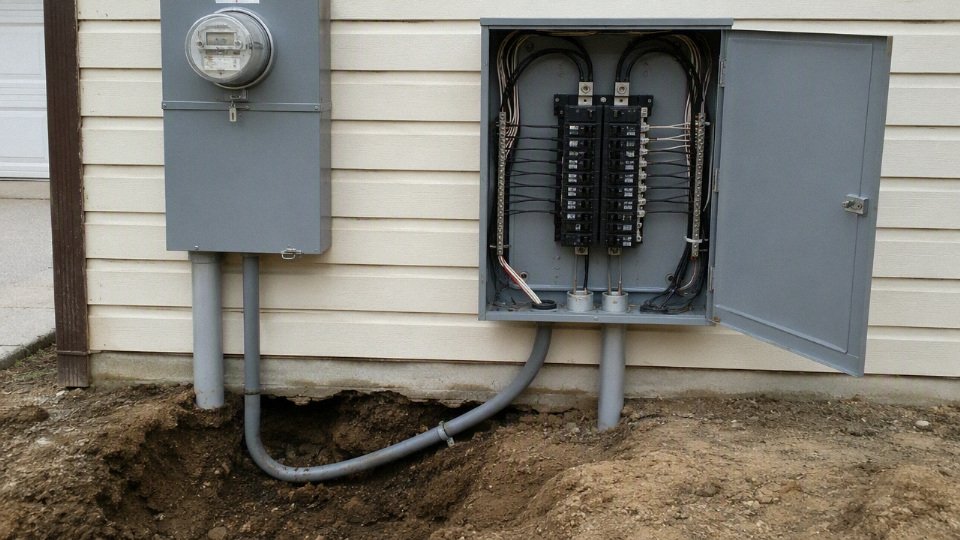
Why three-wire and four-wire answers conflict
Three-wire advice usually comes from one of three places:
- Service lateral discussions, where the utility/service conductors are being confused with downstream feeder wiring.
- Older detached-building installations, which may have been installed under earlier rules or local exceptions.
- Incomplete shorthand, where someone says “three conductors” but is only counting current-carrying conductors and ignoring the equipment grounding conductor.
That distinction is not academic. The neutral is a current-carrying conductor: it carries the imbalance between the two 120 V legs. If a workshop has lights, receptacles, a small compressor control transformer, and a battery charger, the neutral may carry meaningful current for hours.
The equipment grounding conductor is different. It normally carries no load current. Its job is to provide a low-impedance fault path so a breaker or fuse operates quickly when a metal cabinet, raceway, pump frame, or panel enclosure becomes energized. Combining neutral and equipment grounding downstream of the service equipment can put normal neutral current onto metal parts, grounding electrodes, water piping, cable armor, and bonded building steel. That creates shock risk, nuisance voltage, and in wet underground environments it can contribute to corrosion paths that are hard to diagnose later.
Ground rods do not replace the feeder grounding conductor
A detached building may need grounding electrodes, but those electrodes are not a substitute for the equipment grounding conductor run with the feeder. Ground rods help reference the structure to earth and dissipate certain surges or lightning-related energy. They are not reliable enough, by themselves, to clear a line-to-case fault on a 100 amp circuit.
This is a common field mistake: an installer drives two rods at the garage, lands the neutral and grounds together in the subpanel, and assumes the earth will “take care of it.” Soil resistance varies wildly with moisture, rock content, frost, and season. A dry summer site with sandy backfill can have a very different fault path than the same trench in March. Breakers need a metallic return path with low enough impedance to trip promptly; earth is not designed to be that path.
Bonding location decides whether the panel is safe or wrong
Neutral-to-ground bonding is generally made at the service equipment, not at downstream feeder panels. In a normal subpanel, the neutral bar floats on insulating standoffs, the bonding screw or strap is removed, and grounding conductors land on a bonded grounding bar. I like to see installers put the removed bonding screw in a small bag taped inside the panel or note it on the cover schedule; it prevents the next person from “fixing” what was intentionally isolated.
There are service-side arrangements where bonding rules differ, especially around service disconnects, meter-main equipment, separately derived systems, and utility-controlled equipment. That is why the word “service” should not be used casually. If the 100 amp underground run is ahead of the service disconnect, treat it as service work and check the utility book and local service rules before buying cable.
A detached building supplied by a 120/240 V feeder usually needs a separate equipment grounding conductor run with the feeder, even if ground rods are installed at the detached structure.True
This reflects modern feeder grounding practice under commonly applied electrical-code rules, but the final requirement must be checked against the adopted local code, installation date rules, and inspector requirements.
What inspectors and buyers may ask to see
For a small residential job, the paperwork may be light. For a farm, commercial yard, rental property, or industrial outbuilding, expect a more formal review. The useful documents are not bureaucracy for its own sake; they prevent trench rework and wrong cable purchases.
Common inspection or procurement documents include:
- Panel schedules showing the loads served by the 100 amp panel.
- Load calculation confirming that 100 amp capacity is adequate and that neutral load assumptions are reasonable.
- One-line diagram showing service equipment, feeders, disconnects, grounding electrodes, and bonding points.
- Trench inspection record before backfill, including burial depth, warning tape, conduit type, and separation from other utilities.
- Conductor markings or cable datasheets proving insulation type, conductor material, conductor size, voltage rating, and direct-burial or wet-location suitability.
- Torque records for lugs and terminals, especially with aluminum conductors, because under-torqued or over-torqued terminations are a real failure mode.
- Photos before backfill, which are cheap insurance when a future repair crew is standing there with a locator and a shovel.
The trade-off is simple enough: treating every 100 amp underground run as “just three big wires” saves a little planning time up front, then risks a failed inspection, unsafe bonding, or the wrong cable on the reel. Once the trench is open and the panel type is known, conductor count and grounding method should be locked down before procurement; changing from three to four conductors after delivery is the kind of avoidable mistake that leaves expensive cable sitting in the yard.
Specification and procurement checklist
Use a cable schedule, not a one-line request for “100 amp underground wire.” A buyer should be able to send the same schedule to an electrical contractor, distributor, cable factory, inspector, and freight forwarder without each party guessing what was meant.
Minimum cable specification fields
At quotation stage, lock down the electrical construction first. The minimum fields should include:
| Specification field | What to state clearly | Why it matters in procurement |
|---|---|---|
| Conductor material | Copper or aluminum | Drives ampacity, voltage drop, termination hardware, reel weight, and price |
| Conductor size | AWG, kcmil, or mm² as applicable | Prevents substitutions based only on nominal amp rating |
| Number of conductors | Phase conductors, neutral, grounding conductor | Missing grounds or neutrals are a common reason cable is unusable on arrival |
| Insulation type | Such as THWN-2, XHHW-2, USE-2, or project-specified equivalent | Determines wet-location suitability, conduit use, and approval path |
| Voltage rating | Commonly 600 V for many low-voltage feeders, unless project requires otherwise | Must match system and standard requirements |
| Temperature rating | 60°C, 75°C, or 90°C insulation rating, with terminal rating checked separately | Ampacity is often limited by equipment terminals, not just the cable |
| Wet-location rating | Required for underground raceways and many buried installations | Underground conduit is treated as wet in typical code practice |
| Direct-burial rating | Required only if the cable will be buried without raceway where permitted | A conduit-rated wire is not automatically a direct-burial cable |
| Jacket, sheath, or armor | PVC jacket, LSZH jacket, metallic armor, interlocked armor, or none | Affects pulling, sunlight resistance, mechanical protection, and fire requirements |
| Standard compliance | NEC-related listing, UL, CSA, IEC, ASTM, or local standard as specified | Inspectors and import authorities usually care about the mark, not verbal assurances |
| Print legend | Manufacturer, size, voltage, insulation, standard, date or batch code | Field crews and inspectors identify the product from the jacket marking |
A clear cable schedule reduces more commercial risk than shaving a few percent from the unit price. The costly failures are usually not copper versus aluminum price differences; they are wrong insulation, missing grounding conductors, non-accepted listings, reel lengths that cannot be pulled, or documents that do not satisfy the buyer’s customs or inspection process.
Conductor construction details to specify
Do not stop at “copper” or “aluminum.” For underground feeders, the conductor build affects pulling force, termination behavior, bend radius, and long-term connection reliability.
Specify:
- Solid or stranded conductor
- Solid conductors are simple for smaller sizes but become stiff and difficult to route as size increases.
- Stranded conductors are usually preferred for larger underground feeders because they pull and terminate more practically.
- Compact or concentric stranding
- Compact stranded conductors reduce overall diameter, which can help conduit fill and pulling tension.
- Concentric stranding is common and familiar to installers, but may require a slightly larger raceway for the same ampacity class.
- Stranding class
- State the required ASTM, IEC, or project standard rather than relying on a loose description such as “flexible.”
- Extra-flexible conductors can create termination issues if the lug is not rated for that strand class.
- Copper surface condition
- Bare copper is common.
- Tinned copper may be specified where corrosion resistance, marine exposure, or project practice requires it, but it adds cost and should not be selected by habit.
- Aluminum alloy grade
- Where aluminum is used, state the required electrical-grade alloy or applicable standard.
- Terminations must be compatible with aluminum conductors, and joint compound, torque values, and re-torque practices should follow the connector manufacturer’s instructions.
The trade-off is straightforward: a compact stranded aluminum feeder may lower material cost and reduce conduit fill, but it can increase sensitivity to termination quality. A stranded copper feeder is easier to trust in mixed-maintenance environments, especially where crews vary, but it carries a higher metal cost and reel weight.
System data the supplier and contractor need
The electrical system information tells the manufacturer and supplier what the cable is actually serving. Include:
- System voltage, such as 120/240 V single-phase or 120/208 V three-phase.
- Phase and wire arrangement.
- Frequency, usually 50 Hz or 60 Hz depending on country and site.
- Grounding arrangement, including separate neutral and equipment grounding conductor where required.
- Whether the run is a service, feeder, or subpanel supply.
- Expected continuous and non-continuous load.
- Breaker or fuse size protecting the conductors.
- Load type, especially motors, welders, HVAC, pumps, EV charging, or mixed receptacle loads.
- Installation environment: residential, farm, industrial yard, marina, utility area, or commercial site.
This is where many buying errors start. A purchasing department sees “100 amp underground” and orders conductors sized for ampacity only, while the engineer assumed a separate insulated grounding conductor, wet-location rating, and a specific listing. The cable may be electrically close but still fail inspection or be impossible to terminate cleanly in the selected gear.
Route and installation data
Underground cable procurement needs route data because the installed condition changes both the cable design and the reel plan.
Provide:
- One-way circuit length, not just trench length if terminations rise up at both ends.
- Conduit material, such as PVC, HDPE, rigid metal conduit, or intermediate metal conduit.
- Conduit diameter and fill calculation basis.
- Number of bends, bend angles, and approximate bend radii.
- Pull boxes, handholes, vaults, or splice locations.
- Burial depth required by local code and site drawings.
- Soil condition: dry sand, clay, rocky backfill, corrosive soil, high water table, or concrete encasement.
- Ambient temperature and expected soil temperature where known.
- Sunlight exposure at risers or above-ground transitions.
- Oil, fuel, fertilizer, salt spray, wastewater, or chemical exposure.
- Rodent risk and mechanical damage risk from vehicles, tools, or future excavation.
The mechanism is not academic. More bends and smaller conduit increase pulling tension, which raises the chance of jacket scoring, insulation damage, or a crew using lubricant and force to make a bad design work. Longer pulls may need larger conduit, intermediate pull points, lower-friction jacket material, or different reel lengths. The usual ampacity recommendation stops being enough once the route makes installation damage likely.
Compliance documents and quality controls
For domestic work, the inspector may mainly want the correct listing and visible jacket legend. For international projects, the documentation package can be just as important as the cable.
Request the required documents before production or shipment:
- Factory test reports.
- Certificate of conformity.
- UL or CSA listing documentation where required.
- IEC, ASTM, or other standard compliance declarations where specified.
- RoHS or REACH statements if the buyer’s market requires them.
- Packing list.
- Drum schedule.
- Batch, lot, or reel traceability records.
- Mill certificates or conductor material certificates where contractually required.
Quality control requirements should also be named in the purchase specification, not argued after inspection:
- Conductor resistance test.
- Insulation thickness measurement.
- Spark testing during production where applicable.
- High-voltage withstand testing according to the specified standard.
- Overall diameter and dimensional checks.
- Marking and print legend verification.
- Reel or drum inspection before shipment.
- End sealing and moisture protection check.
A cable can meet the requested conductor size and still be rejected if its listing, marking, wet-location rating, or documentation does not match the project requirement.True
Conductor ampacity is only one acceptance criterion. Underground electrical work is commonly checked against installation conditions, approved wiring method, equipment ratings, and applicable product standards.
Logistics, reels, and project identification
For bulk procurement, logistics can decide whether the cable is usable on the day the trench is open. State delivery length tolerances and whether exact cut lengths are required. If a 420 ft pull is planned, a reel supplied at 390 ft plus a second short reel creates a splice problem, not a minor shipping variation.
Specify:
- Required reel lengths and allowable tolerance.
- Wooden or steel reel packaging.
- Reel flange diameter and maximum reel weight if the site has handling limits.
- Moisture protection, end caps, and wrapping.
- Export documentation, commercial invoice, packing list, and certificate requirements.
- Destination port or delivery address.
- Indoor, outdoor, or covered storage conditions.
- Maximum stacking limits if relevant.
- Project lot identification, cable tag numbers, and drum numbers matching the cable schedule.
This is a place where plant-floor discipline helps. Label the reel for the load it serves, not just the size. “Building B feeder, 100 A, panel BP-1” prevents a forklift driver or subcontractor from sending the right cable to the wrong trench.
Using a manufacturer for project-specific supply
Shandong Jinda Special Cable Group Co., Ltd., established in 1987, is positioned for this kind of procurement work because its organization covers R&D, production, sales, technical support, and after-sales service across multiple production bases. For international buyers, that matters when the order needs more than catalog stock: conductor selection, insulation construction, testing documents, packaging method, reel schedule, and shipment records all have to line up.
The most useful request to a cable manufacturer is not “quote your best 100 amp cable.” Send the cable schedule, applicable standard, installation method, destination market, required documents, and reel plan. That gives the supplier enough information to confirm what can be manufactured, what must be listed or certified through the proper channel, and where the specification still needs approval from the project engineer or local authority.
Installation risks and safeguards
Most 100 amp underground failures are not caused by a mysterious cable defect; they come from using the right-looking conductor in the wrong environment, damaging it during installation, or losing discipline at terminations and inspections. Treat the underground run as a wet, mechanically exposed, inspectable electrical system, not just a length of wire between two panels. That mindset prevents most failed inspections and many later service calls.
Underground raceways should be treated as wet locations, even when conduit is used.True
This is a standard code and field practice principle: underground conduit commonly accumulates moisture through condensation, joints, and temperature cycling, so conductor insulation must be suitable for wet locations. Always verify the exact permitted wiring method against the current local electrical code.
Common failure points show up in a fairly predictable pattern:
- Wrong insulation rating
- Dry-location building wire is not acceptable just because it is pulled inside conduit. Underground raceways collect water; I have opened risers that looked sealed and still had standing water at the low point.
- Specify conductors and cable assemblies with insulation and jackets listed for the actual installation method: wet location, direct burial where applicable, sunlight resistance on exposed risers, and temperature rating compatible with the terminals.
- Undersized conductor
- The common mistake is applying the dwelling-service allowance everywhere. In many ordinary 100 amp underground feeder situations, 3 AWG copper or 1 AWG aluminum is the typical 75°C ampacity-based starting point, while 4 AWG copper or 2 AWG aluminum may only be permitted in certain dwelling service or feeder cases.
- If the inspector rejects the basis, the cheap conductor becomes expensive fast: re-pulling, trench reopening, delayed utility coordination, and a very annoyed owner.
- Excessive voltage drop
- A conductor can be legal on ampacity and still disappointing in operation. Long runs to a detached shop, pump house, gate equipment, or agricultural load may start motors weakly, dim lights, or nuisance-trip equipment under peak load.
- Upsizing improves voltage performance and reduces heating losses, but it increases cable cost, conduit size, pulling tension, and lug compatibility issues. The preferred choice flips when the load is intermittent, lightly loaded, or close enough that voltage drop is not the controlling factor.
- Improper aluminum termination
- Aluminum is a sound engineering choice when specified and installed correctly. Problems begin with incompatible lugs, no surface preparation where required, oxide on the conductor, missing antioxidant compound where specified by the connector manufacturer, or “good and tight” torque done by feel.
- Use AL-rated terminals, strip without nicking strands, follow the lug manufacturer’s preparation instructions, and record torque with a calibrated torque wrench. A hot aluminum termination usually starts as a small resistance problem; over time, load cycling makes it worse.
- Neutral and ground errors
- In a subpanel, the neutral must normally be isolated from the enclosure and equipment grounding conductor. Bonding neutral and ground downstream can put return current on metal raceways, enclosures, and grounding paths.
- Do not use ground rods as a substitute for an equipment grounding conductor. Grounding electrodes serve a different job; they do not provide the same low-impedance fault-clearing path back to the source.
- Conduit fill and pulling damage
- Too many conductors in a small raceway, too many bends between pull points, poor lubricant choice, sharp conduit edges, and rough field-cut PVC can scrape or stretch insulation.
- Bigger conduit often looks like wasted money on a bill of material, but it buys lower pulling tension, easier future replacement, better heat dissipation conditions, and fewer damaged conductors. That trade-off is usually worth it on long or bent underground runs.
- Inadequate burial protection
- Shallow cover, no warning tape, rocky backfill, vehicle loading, and exposed risers are mechanical failure invitations.
- Bed the raceway or direct-burial cable in suitable material, remove sharp rock contact, protect risers with rigid conduit or approved guards where exposed, and verify burial depth against the applicable code, wiring method, and traffic loading.
- Poor moisture control
- Open conduit ends, unsealed risers, cracked fittings, and damaged jackets allow water migration. Moisture does not need to cause an immediate fault to be a problem; it can lower insulation resistance, corrode terminations, and accelerate jacket deterioration.
- Seal where required, use listed fittings, avoid low-point traps where practical, and inspect jacket condition before backfill. A roll that was dragged across gravel in the yard deserves a closer look before it disappears underground.
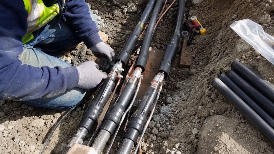
A planned inspection sequence prevents the usual “cover it now, fix it later” mess. Use a short field checklist and make someone responsible for signing it before the trench is closed:
- Pre-pull inspection
- Confirm conduit size, bend count, pull boxes, burial depth, riser protection, and raceway cleanliness.
- Check for sharp edges, missing bushings, crushed conduit, and water standing in low spots.
- Insulation check
- Verify conductor or cable markings match wet-location or direct-burial requirements as specified.
- Inspect for cuts, flattened sections, jacket damage, and abrasion after pulling.
- Conductor identification
- Confirm phase conductors, neutral, and equipment grounding conductor are correctly identified at both ends.
- Check that conductor count matches the service, feeder, or subpanel design.
- Torque record
- Record lug type, conductor material, terminal rating, torque value, tool used, and installer initials.
- Recheck aluminum termination instructions against the actual connector, not just the panel label.
- Trench inspection
- Verify burial depth, warning tape placement, backfill condition, conduit supports, sweeps, and riser protection before cover.
- Photograph open-trench conditions for project records; it saves arguments later.
- Final energization approval
- Confirm inspection release, panel labeling, neutral-ground separation where required, grounding electrode connections where applicable, and basic electrical tests before load is applied.
The boundary on all of this is simple: local code, utility rules, equipment listings, and the inspector of record govern the installation. Good procurement can buy the right cable, but safe energization depends on field execution being documented before the trench is gone.
Frequently asked questions
What size underground wire do I need for 100 amp service?
For many standard 100 amp underground feeder designs, the usual starting point is 3 AWG copper or 1 AWG aluminum when using the 75°C ampacity column and terminals rated for that use. That answer still has to be checked against the local electrical code, insulation type, installation method, conductor count, ambient conditions, and voltage drop.
For certain dwelling service or dwelling feeder applications, code rules may allow 4 AWG copper or 2 AWG aluminum. That allowance is not a blanket rule for every shop feeder, detached building, pump supply, or commercial panel. If the job is not clearly inside that dwelling rule, many inspectors and engineers will expect the more conservative 3 AWG copper or 1 AWG aluminum basis before voltage-drop upsizing.
Can I use 2 AWG aluminum for 100 amps?
Yes, 2 AWG aluminum may be acceptable for certain 100 amp dwelling service or dwelling feeder installations where the applicable dwelling allowance is valid. It should not be treated as a universal 100 amp aluminum feeder size.
The catch is the word “dwelling.” A 100 amp feeder to a house panel may be reviewed differently from a 100 amp feeder to a detached workshop with welders, a barn panel, a small commercial unit, or a pump house. Terminal temperature ratings matter too; if the equipment is only rated in a way that changes the usable ampacity basis, the paper size can stop being acceptable. Aluminum also needs correct terminations, antioxidant where required by the connector manufacturer, and torque with a proper torque screwdriver or wrench, not “good and tight” by feel.
Can I use 4 AWG copper for 100 amps?
4 AWG copper may be permitted for some 100 amp dwelling service or feeder applications, but 3 AWG copper is the safer standard answer outside that allowance. This is why two electricians can give different answers and both may be thinking of different code paths.
In practice, 4 AWG copper often appears in discussions around residential service entrance or dwelling feeder sizing. Once the installation is a general feeder, a non-dwelling application, or a situation where the dwelling allowance does not apply, 3 AWG copper is commonly used as the baseline for 100 amps under typical 75°C sizing. Long runs may still push the design larger for voltage drop.
What wire is best for underground conduit?
For underground conduit, commonly used individual conductor insulation types include THWN-2 and XHHW-2, provided the specific product is listed for wet locations and suitable for the installation. Underground conduit is normally considered a wet location because water eventually gets in, no matter how neatly the PVC was glued.
THWN-2 is common and widely stocked. XHHW-2 is often chosen where buyers want tougher insulation or better handling characteristics on larger feeders, though availability and pulling behavior vary by manufacturer. The conduit fill, bend count, pulling distance, lubrication, and conductor stiffness all affect whether the installation goes smoothly. A short straight trench and a 150 ft run with several sweeps are not the same job.
Can USE-2 wire be run inside a house?
USE-2 is intended for underground service entrance use and has limitations inside buildings. In many installations, USE-2 conductors must transition outside or near the point of entry to a wiring method approved for interior use, unless the specific cable or conductor carries additional markings that permit the indoor application.
This is a common purchasing mistake: someone orders “direct burial wire” and assumes it can run from the trench, through the wall, across a basement, and into a panel. The marking on the cable decides what is allowed, not just the conductor size. Some products have multiple ratings, such as USE-2 plus another building-wire rating, but that must be verified on the print legend and datasheet.
How many wires are needed for a 100 amp subpanel?
A typical 120/240 V single-phase 100 amp subpanel feeder uses four conductors:
- Two ungrounded phase conductors, often called “hots”
- One insulated neutral conductor
- One equipment grounding conductor
At the subpanel, the neutral and equipment grounding bar are normally isolated from each other. The bonding connection belongs at the proper service equipment point, not casually repeated in every downstream panel. This is one of those inspection items that gets caught quickly because it affects fault-current paths and touch voltage during a fault.
What size ground wire is needed for a 100 amp feeder?
A common equipment grounding conductor size for a 100 amp feeder is 8 AWG copper or 6 AWG aluminum, based on the overcurrent protective device rating. Local code, conductor material, raceway type, and any required adjustments still need to be checked.
Do not confuse the equipment grounding conductor with the grounded neutral conductor. They serve different purposes and are sized by different rules. If the feeder conductors are upsized for voltage drop, the equipment grounding conductor may also need to be reviewed under the applicable code rules rather than left at the first size someone remembered.
Does underground wire have to be in conduit?
Not always. Whether conduit is required depends on the cable type, burial depth, exposure to damage, building entry method, local code, and the authority having jurisdiction.
A practical split is:
- Individual conductors, such as THWN-2 or XHHW-2, normally need a raceway.
- Direct-burial cable may be allowed underground without continuous conduit if it is listed for that use.
- Risers, building entries, driveways, rocky soil, and exposed sections often need extra physical protection even when the buried cable itself is direct-burial rated.
Many contractors still sleeve direct-burial cable in conduit at risers and vulnerable areas because shovel damage, mower hits, and settlement around foundations are not theoretical problems.
How far can 100 amp wire be run underground?
There is no single maximum distance for 100 amp underground wire. The practical limit is set by voltage drop, actual load, conductor material, system voltage, acceptable performance at the equipment, and sometimes starting current for motors or compressors.
A feeder that rarely carries more than 40 amps behaves differently from one serving continuous HVAC, EV charging, shop tools, or irrigation pumps. Aluminum has higher resistance than copper at the same AWG size, so it may need to be upsized sooner on long runs. For a serious design, calculate voltage drop using:
- One-way circuit length
- Load current, not just breaker size
- Voltage, such as 120/240 V single-phase
- Conductor material and size
- Acceptable voltage drop target
- Motor starting or sensitive electronics, if present
Should I choose copper or aluminum for a long underground run?
For long underground runs, copper gives lower resistance and smaller conductor size, while aluminum usually wins on material cost and is widely used for service and feeder conductors. The better choice depends on total installed cost, not just the cable price per foot.
Copper can reduce conduit size, pulling difficulty, voltage drop, and termination bulk. Aluminum can save a meaningful amount of money on long feeders, especially where larger conductors are already expected and equipment lugs are rated for aluminum. The trade flips toward copper when space is tight, the run has difficult bends, voltage drop is marginal, or terminations are small. It leans toward aluminum when the route is long, the raceway is planned correctly, and the crew is disciplined about torque, connector ratings, and handling.
2 AWG aluminum and 4 AWG copper are always acceptable for any 100 amp underground feeder.False
Those sizes may be permitted under certain dwelling service or feeder rules, but standard 100 amp feeder sizing often starts at 1 AWG aluminum or 3 AWG copper before project-specific checks.
Verify your 100 amp cable schedule
Start with the cable schedule, not a loose “100 amp wire” request. For most standard 75 °C ampacity selections, evaluate 3 AWG copper or 1 AWG aluminum as the normal 100 amp underground basis; consider 4 AWG copper or 2 AWG aluminum only where the dwelling sizing rule is valid and accepted by the authority having jurisdiction. That last condition matters, because a cable that passes a pricing review can still fail inspection if the job is actually a feeder, subpanel supply, commercial circuit, agricultural load, or installation with different terminal assumptions.
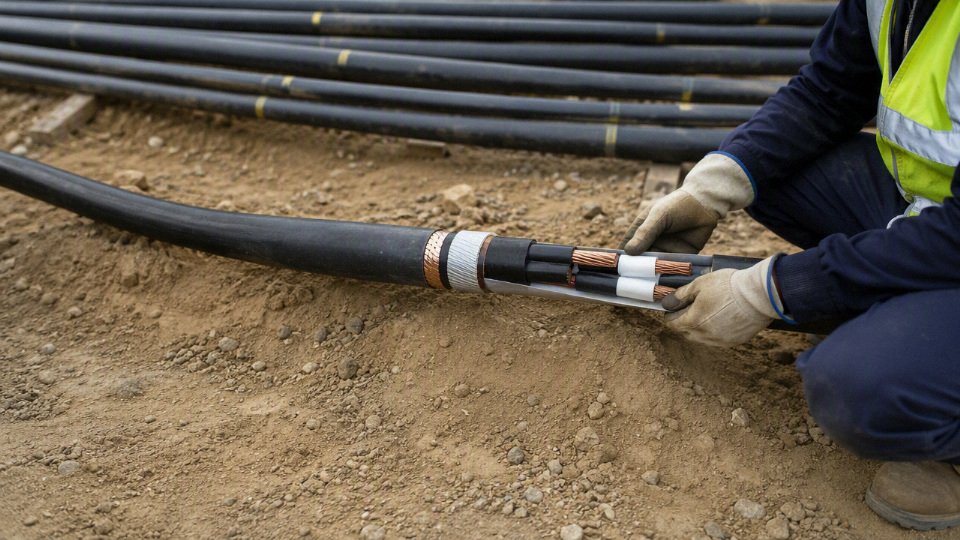
Before ordering, lock down these items in writing. I prefer to see them on one schedule sheet, because scattered notes in emails are how the wrong neutral, insulation, or reel length gets bought.
- Load calculation
Confirm that 100 amp is the correct overcurrent rating, not just the panel label or a convenient round number. - One-way route length
Measure the trench path, including risers, sweeps, offsets around foundations, and slack at terminations. Voltage drop is driven by conductor resistance over length; a code-legal ampacity size may still give poor motor starting or nuisance equipment behavior on a long detached-building run. System voltage and phase
State whether the circuit is 120/240 V single-phase, 120/208 V three-phase, 277/480 V, or another system. This affects conductor count, neutral loading, and product marking.Service, feeder, or subpanel classification
This controls grounding, bonding, neutral isolation, and whether an equipment grounding conductor is required.Conductor material
Copper gives smaller conductors and more forgiving terminations; aluminum can reduce material cost but needs correct lugs, antioxidant practice where specified, torque discipline, and bend-space checks.Insulation and cable type
Specify insulation suitable for wet locations and the intended underground method. Underground conduit is usually treated as a wet location in code practice.Direct burial or conduit method
Direct-burial cable and individual conductors in conduit are not interchangeable purchasing descriptions. Conduit fill, pulling tension, sweep radius, and jacket toughness all affect installation time.Neutral size
Do not assume the neutral is automatically the same size or automatically reduced. It depends on load profile and code allowance.Equipment grounding conductor size
A common reference point for a 100 amp feeder is 8 AWG copper or 6 AWG aluminum, subject to the overcurrent device rating and local code.Termination compatibility
Match conductor material, strand class, insulation temperature rating, lug listing, and equipment terminal rating. A 90 °C insulated conductor may still be limited by 75 °C terminals for ampacity selection.Local approval path
Confirm the applicable code edition, utility rules if it is service-related, and inspector expectations before the purchase order is released.
For procurement, request more than a price per foot or meter. A useful documentation package should include:
- Cable datasheet with conductor, insulation, voltage rating, and construction details
- Compliance certificate for the specified standard
- Factory test report for the supplied lot or shipment
- Reel schedule with lengths, reel numbers, and shipping weights
- Print legend showing size, voltage, standard, manufacturer, and traceability marks
- Packing plan suitable for site handling, export shipping, or phased installation
- Installation notes covering bend radius, pulling precautions, storage, and termination handling
The expensive mistake is ordering by amp rating alone. That shortcut can produce a cable that is electrically undersized for voltage drop, mechanically awkward to pull through the selected conduit, unsuitable for wet underground conditions, noncompliant with the installation category, or incompatible with the actual terminals on the gear. The trade-off is familiar: buying the minimum conductor can reduce initial material cost, while upsizing can improve voltage performance and installation margin; the preferred choice flips when route length, starting loads, conduit congestion, or inspection risk cost more than the conductor savings.
If you want Jinda to help verify a suitable 100 amp underground cable specification for quotation and supply, send the project voltage, phase, route length, installation method, preferred standard, conductor material preference, service or feeder classification, required documentation, and any drawings or site photos available. Jinda’s technical team can review the cable schedule against those inputs and support a quotation package with the appropriate product documentation for project purchasing.