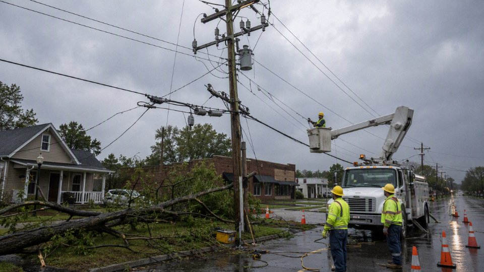
A windstorm drops a tree limb across a feeder, the neighborhood goes dark, and the first question from ratepayers is obvious: why was that line still in the air? The operational pain is visible in bucket trucks, mutual-aid crews, spoiled inventory, idled production, and customers running diesel generators in the parking lot. Burying lines can reduce that exposure, but the decision runs straight into capital cost, repair time, soil conditions, cable thermal limits, and who pays the bill.
Americans don’t bury most power lines because underground distribution typically costs several times more to build—often about $1 million to $5 million per mile versus roughly $100,000 to $400,000 for new overhead lines—and buried faults can take longer to locate, excavate, splice, and restore despite fewer storm-related outages.
That answer sounds simple until you separate a suburban lateral from a downtown duct bank, or a 13.8 kV distribution circuit from a high-voltage transmission corridor. The economics change with trenching conditions, load density, easements, transformers, jointing labor, and outage tolerance. The uncomfortable truth is that underground cable is not automatically “better”; it is better under the right operating and financial conditions.
Cost, density, and geography
Universal undergrounding is uncommon in the United States because the country has a lot of line miles serving relatively few customers per mile in many places, and underground construction usually costs several times more than overhead distribution. The decision changes in dense districts, new developments, and high-value corridors, but it breaks down quickly on long feeders, difficult terrain, and retrofit work.
A distribution pole line is not cheap, but it is mechanically simple compared with a buried system. A typical overhead project buys poles, anchors, crossarms or brackets, insulators, conductors, cutouts, surge arresters, transformers, and line hardware. The labor is specialized, yet access is often from bucket trucks, digger derricks, backyard machines, or tracked equipment. Repairs can be ugly after a storm, but the failed part is usually visible: a broken pole, a tree on a phase, a blown fuse, a damaged transformer lead.
Underground distribution changes the cost structure completely. The cable itself is only one line item. The job may require:
- Trenching, boring, or rock excavation
- PVC conduit, HDPE conduit, or concrete-encased duct banks
- Manholes, handholes, transformer pads, switch vaults, and pull boxes
- Cable pulling equipment, pulling lubricant, rollers, and tension monitoring
- Thermal backfill where native soil will not dissipate heat adequately
- Medium-voltage terminations, elbows, splices, and separable connectors
- Grounding and bonding systems
- Pavement, curb, sidewalk, driveway, and landscape restoration
- Traffic control, lane closures, night work, and police details in some cities
- Utility locating and relocation for gas, water, sewer, telecom, drainage, and street lighting
That is why broad cost comparisons usually land in very different bands. New overhead distribution often falls somewhere in the hundreds of thousands of dollars per mile, commonly around $100,000 to $400,000 per mile depending on conductor size, pole class, terrain, labor rates, and permitting. Underground distribution is often in the millions per mile, roughly $1 million to $5 million per mile in many planning discussions, with dense urban work, rock, contaminated soil, groundwater, or heavy traffic control pushing higher. Those are not bid numbers for a specific route; a serious estimate needs drawings, soil data, utility conflict information, restoration requirements, cable ampacity, and local labor assumptions.
Underground distribution usually costs more to build than overhead distribution, even though it can reduce outages caused by wind, trees, ice, and vehicle impacts.True
This is consistent with common utility planning practice. The cost gap comes mainly from civil work, duct systems, vaults, splicing, surface restoration, and utility conflicts, while the reliability benefit is strongest against above-ground physical damage.
Why density changes the economics
A mile of power line in a downtown district may serve hundreds or thousands of customers, commercial loads, elevators, data rooms, transit assets, and high-value street frontage. A mile of rural line may serve a handful of homes, a pump station, a grain bin, or a few ranch services. Same mile, completely different economics.
The mechanism is simple: cost recovery follows the number and value of customers served. If a $3 million underground segment supports a dense block with high demand, expensive outage consequences, limited pole space, and strong aesthetic pressure, the cost per customer and per kilowatt of connected load may be tolerable. If the same $3 million serves 18 rural meters across several miles, the rate impact is hard to justify unless there is a specific hazard, public funding source, or customer contribution.
Dense areas also create coordination opportunities. Underground power can be installed during road reconstruction, rail station work, utility corridor upgrades, streetscape projects, or new real estate development. If the street is already open and multiple utilities are moving, the incremental cost of installing power ducts may be much lower than opening the same street just for electric conversion two years later. Anyone who has watched a city cut fresh asphalt three times in one season knows why coordination matters.
There is a trade-off, though. Dense areas make undergrounding more valuable, but they also make it harder to build. Crews fight for space with gas mains, fiber ducts, water services, old clay sewer laterals, steam lines in some cities, and undocumented abandoned utilities. A shallow trench that looks easy on a plan can turn into vacuum excavation, hand digging, redesign, and a week of traffic control because an old service line is six inches from the proposed duct bank.
America’s route length is part of the engineering problem
The United States is not just large; its electrical distribution system is stretched across many settlement patterns. Long suburban feeders run behind shopping centers, through cul-de-sacs, along drainage easements, and across road crossings added decades after the original line was built. Rural cooperatives maintain miles of line along agricultural service roads, county highways, fence lines, and wooded rights-of-way. Western utilities may cross desert, rock, and long empty distances. Mountain utilities deal with slope stability, narrow roads, frost depth, and access windows. Coastal utilities face salt exposure, high groundwater, storm surge, and hurricane winds.
Those conditions do not point to one universal answer. Undergrounding may be attractive in a coastal town center where wind exposure, tree damage, tourism aesthetics, and business interruption all matter. The same approach may be poor value on a long mountain lateral where rock trenching is expensive and fault repair would require difficult excavation in winter. In forested fire-risk areas, targeted undergrounding can make sense on selected circuits, but it competes with covered conductor, spacer cable, aggressive vegetation management, sectionalizing, recloser settings, and relocating lines to better access routes.
High-voltage transmission is a different cost category again. Underground transmission is not just “bigger distribution cable.” At higher voltages, insulation systems, thermal limits, joint bays, reactive power compensation, grounding, sheath bonding, installation method, and testing requirements become major design drivers. A buried transmission circuit may need engineered thermal backfill or forced cooling in special cases, large splice vaults or joint bays at planned intervals, and careful management of charging current on long AC cable runs. Costs can reach far higher multiples than distribution undergrounding, and the acceptable route may be controlled as much by permitting and thermal performance as by cable price.
Why retrofit work hurts the budget
Retrofitting an existing overhead neighborhood is usually far more expensive than installing underground service during new construction. In a new subdivision, the developer can grade roads, install ducts, set transformer pads, coordinate water and gas, pour sidewalks later, and bring service laterals to homes before lawns, fences, mature trees, and driveways exist. Crews are working in dirt, not in someone’s finished front yard with a sprinkler line every few feet.
A conversion project has to preserve electric service while building a second system. That can mean temporary feeds, staged cutovers, switching plans, outage notices, generator provisions for sensitive customers, and extra field labor. The utility may need new easements if the old overhead line sits in a rear-lot position that is unsuitable for underground equipment. Pad-mounted transformers require physical space and vehicle access; not every neighborhood has a neat place to put them without upsetting sight lines, parking, landscaping, or property owners.
Customer-side work can be another surprise. A house served from an overhead weatherhead may need a new meter base location, underground service lateral, conduit riser, panel coordination, grounding upgrades, or local code corrections before the conversion is accepted. Multiply that by hundreds of homes and the “just bury the wires” idea becomes a civil, electrical, legal, and customer-service project.
This is the counter-intuitive part: underground service can be economically rational when built from the start, while converting the same area 25 years later can look financially unreasonable. The first case avoids duplicate infrastructure and builds around open access. The second case demolishes and restores finished surfaces, works around unknown utilities, negotiates access, maintains the old system during construction, and then removes or abandons pieces of it after cutover.
Who pays for undergrounding
The payer depends on why the project is being done and who receives the benefit. In practice, the funding package is often as important as the engineering estimate.
Common payment routes include:
- General utility ratepayers: The utility includes approved capital spending in its rate base, subject to regulator review where applicable. This spreads cost broadly but requires justification against other reliability investments.
- Municipal undergrounding districts or special assessments: A city or town forms a district and charges benefiting properties over time. This is common where streetscape, tourism, property value, or civic design is part of the driver.
- Developers: New subdivisions, industrial parks, and commercial sites often include underground distribution as part of site development. The cost is embedded in land, lease, or project economics.
- Homeowners associations: Gated communities or planned neighborhoods may fund or require underground service, especially where aesthetics and tree-lined streets are priorities.
- Public agencies and resilience grants: Storm-hardening, wildfire mitigation, military base resilience, transportation corridors, or critical public facilities may qualify for public funding, but grants usually come with scope, schedule, reporting, and eligibility limits.
- Individual customers: A property owner requesting conversion from overhead to underground service may pay for the service lateral, trenching, conduit, meter changes, and utility fees, depending on local tariff rules.
The practical boundary is this: undergrounding looks strongest where many customers, high outage costs, public-space value, or new construction timing share the cost of each mile. It looks weakest where long route length, low customer density, rock, groundwater, or retrofit constraints push civil cost onto a small number of meters. A utility planner will not settle that question from a national average; they need feeder maps, outage history, soil and pavement conditions, customer count, load served, restoration scope, and a clear answer on who is actually paying the bill.
Reliability beyond storm headlines
Underground power is usually better at avoiding the most visible storm failures, but it is not automatically the more reliable system in every operating sense. The right comparison separates how often customers lose power from how long they stay out, what hazard caused the event, and whether the surrounding network can isolate damage and back-feed load.
Underground distribution circuits generally experience fewer wind, tree, ice, and pole-impact outages than overhead circuits, but cable faults can take longer to locate and repair.True
This follows standard utility operating experience: underground conductors are shielded from many above-ground hazards, while failed buried cable often requires fault location, switching, excavation, splicing, and site restoration before service is restored.
Overhead systems fail for reasons any line crew can identify from the road after a bad night:
- Wind-blown limbs bridging phases or pulling service drops down
- Whole trees leaning into conductors after saturated soil loses grip
- Ice loading that increases conductor weight and galloping forces
- Pole failures from rot, ground-line decay, storm loading, or vehicle impact
- Wildlife contact at transformers, cutouts, risers, and open secondary connections
- Lightning exposure on long rural spans
- Wildfire ignition risks from conductor slap, failed hardware, or vegetation contact
Burying the line removes many of those exposure points. A cable in conduit or direct-buried trench does not care much about a maple limb coming down in a March storm. It is not whipped by wind, it does not accumulate radial ice like an aerial conductor, and it is not hanging on a pole at the edge of a road where a pickup truck can take it out at 2 a.m. In fire-prone areas, undergrounding can also reduce some ignition paths associated with overhead conductors and hardware, though it does not eliminate fire risk from substations, transformers, secondary equipment, or customer-side installations.
The trap is treating “protected from weather” as the same thing as “immune to failure.” Underground systems have their own failure menu, and some items are less forgiving because they stay hidden until the insulation system is already compromised:
- Water ingress: Moisture enters through damaged jackets, bad terminations, failed seals, cracked conduit, or flooded vaults. Once water reaches insulation defects, electrical trees can grow under voltage stress.
- Insulation aging: Medium-voltage cable insulation degrades with heat, moisture, voltage stress, contamination, and time. Older cable families and poorly controlled installation practices can make this worse.
- Thermal overload: Soil is not a perfect heat sink. Cable ampacity depends on burial depth, duct bank layout, soil thermal resistivity, load factor, adjacent energized circuits, and seasonal ground conditions. A feeder that looked acceptable on paper can run hot in dry backfill or congested duct banks.
- Poor splices and terminations: In my experience, a mediocre splice is one of the most expensive “small” workmanship problems in a utility system. Contamination, wrong tooling, bad shield cutback, poor crimping, or rushed heat-shrink work can shorten service life dramatically.
- Dig-ins: Excavators, fence posts, directional drills, and utility crossings still damage buried cable despite locating procedures. A nicked jacket may not fail the same day; it may fail after moisture and load cycling do their work.
- Neutral corrosion and grounding problems: Concentric neutrals and grounding conductors can deteriorate in corrosive soils or wet ducts, affecting fault return paths and protection behavior.
- Flooding and vault contamination: Road salt, silt, hydrocarbons, sewage, and brackish water are hard on terminations, elbows, switches, and exposed metallic parts.
- Rodent damage in accessible spaces: Cable in vaults, basements, tunnels, and cabinets is not fully isolated from animals unless the civil and sealing work is maintained.
- Manufacturing or installation defects: Cable quality matters, but so do pulling tension, sidewall pressure, bend radius, reel handling, cleanliness, and test discipline before energization.
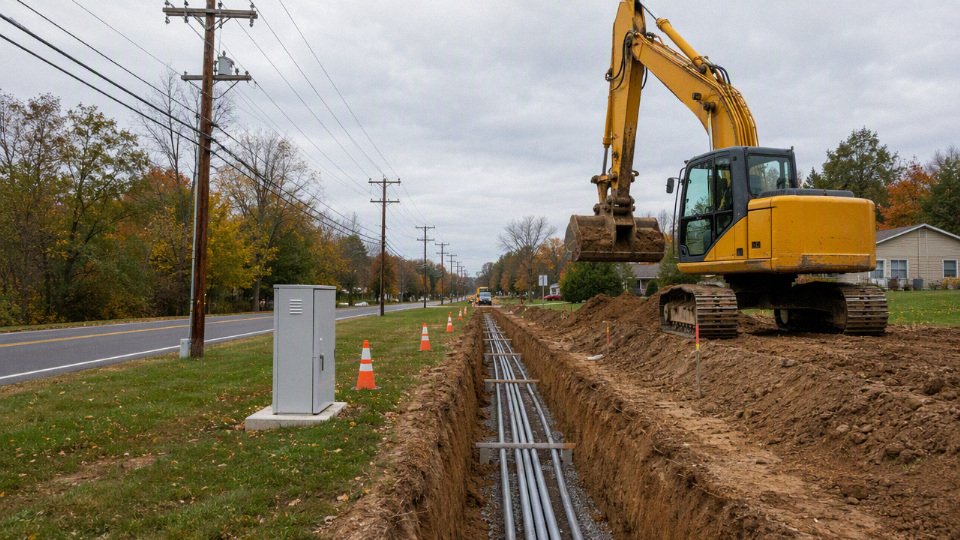
The repair sequence is where many public conversations get sideways. If a storm drops a span of overhead primary, the damage is often visible. A crew can patrol the feeder, open switches, replace a crossarm, hang a transformer, pull in a new span, and re-energize sections with a bucket truck and stocked hardware. It may be ugly work in rain and wind, but the failed part is in the air, not under a paved arterial with a gas main beside it.
With underground cable, the first hour may be spent proving where the fault is and how to isolate it safely. Depending on the system, crews may need:
- Switching orders to isolate the failed section without overloading an alternate feeder.
- Fault indicators, thumpers, time-domain reflectometry, or other locating equipment.
- Drawings that actually match the field, which is not guaranteed in older districts.
- Excavation permits, traffic control, utility locates, and sometimes police detail.
- Dewatering if the manhole, vault, or trench is flooded.
- Qualified cable splicers and the correct splice kits, elbows, terminations, and test equipment.
- Replacement cable of the right voltage class, conductor size, insulation type, and shield configuration.
- Pavement, sidewalk, landscaping, or roadway restoration after the electrical repair is finished.
That is why underground feeders can show fewer interruptions while still producing long-duration outages when a serious cable fault occurs. The preferred system flips with the hazard profile: in a tree-heavy suburban area with frequent wind events, underground laterals may cut nuisance outages sharply; in a rocky rural area with long feeders and limited crew access to specialized splicing resources, selective overhead hardening may deliver better service per dollar.
Reliability also lives above the individual line segment. A plain radial underground feeder with no alternate source can still leave everyone dark from one failed cable, transformer, or switch. A well-sectionalized overhead feeder, by contrast, may take several hits in a storm but restore most customers quickly through automated switching and field sectionalizing.
Utilities usually get better results by comparing packages of improvements, not by arguing overhead versus underground as a religion:
| Reliability measure | What it improves | Typical plant-floor equivalent in utility work |
|---|---|---|
| Looping and feeder ties | Reduces customers affected by one fault | Gives operators another path to feed load |
| Sectionalizers and reclosers | Limits outage area and clears temporary faults | Isolates the bad zone instead of dropping the whole line |
| Automated switching | Cuts restoration time | Removes waiting time for manual switching crews |
| Vegetation management | Reduces overhead fault frequency | Preventive maintenance, not emergency repair |
| Pole class upgrades and guying | Improves storm survivability | Mechanical derating margin for bad weather |
| Covered conductors | Reduces some contact faults | Not insulated cable, but more tolerant of incidental contact |
| Targeted undergrounding | Removes exposure at the worst spans | Best used where tree, wind, fire, or access risk is concentrated |
| Microgrids and local generation | Keeps critical loads served | Especially relevant for hospitals, water plants, shelters, and communications sites |
Pad-mounted equipment is the part many owners miss. A feeder may be “underground,” but the transformers, switch cabinets, riser poles, terminations, vault lids, and substations still have addresses in the physical world. Put them in a floodplain, next to a road without bollards, in a coastal salt environment, or in a low vault that takes stormwater, and the buried cable has not bought full resilience. I have seen cabinets where the cable was fine but the operating mechanism, elbows, or controls were the weak link because water and salt got to the accessible equipment first.
This is why utility reliability planning uses metrics rather than appearances. Common measures include outage frequency, outage duration, customer minutes interrupted, number of critical customers served, restoration crew availability, material lead time, switching flexibility, and expected avoided storm cost. A homeowner sees the pole line and thinks, reasonably, “bury it.” A utility planner has to ask which customers benefit, which failure modes disappear, which new ones appear, how long repairs will take, and whether the same capital would prevent more customer-minutes of outage somewhere else on the system.
A buried system can be the right choice, especially in dense districts, high-wind corridors, heavily treed subdivisions, critical campuses, and selected wildfire-exposure zones. It stops being the obvious answer when the network lacks redundancy, the civil environment is wet or congested, specialized repair resources are thin, or exposed above-ground equipment remains the true weak point.
Engineering limits below grade
Putting power lines underground is not a matter of taking the same overhead conductor and burying it. Below grade, the cable becomes part of a thermal, civil, and maintenance system where soil, ducts, joints, moisture, records, and installer workmanship all affect whether the circuit survives at rated load. Undergrounding reduces exposure to wind and trees, but it transfers a lot of risk into places operators cannot see without test equipment and excavation.
Heat has nowhere easy to go
An overhead conductor sheds heat directly into moving air. If the wind picks up, its cooling improves; if the conductor temperature rises, operators can often see sag limits, clamp issues, or hot spots with inspection tools. Underground cable is different. Heat must move through:
- The conductor and strand screen
- The insulation system
- Metallic shield or concentric neutral
- Jacket or sheath
- Duct wall, if installed in conduit
- Grout, thermal backfill, or native soil
- Nearby soil, pavements, foundations, other utilities, and sometimes other energized circuits
That heat path is why ampacity tables are never just “copper size equals amperes.” Soil thermal resistivity matters heavily, and it changes with moisture. A duct bank that performs acceptably in damp spring soil can run hotter during a dry August after a long peak-load period. Burial depth, spacing between circuits, duct arrangement, load factor, and proximity to steam lines, district heating, sewer mains, or other power cables all shift the result.
A common mistake in early cost estimates is to treat underground cable rating as if it were a catalog property. It is not. The same cable can carry different current depending on whether it is direct-buried in engineered thermal backfill, pulled through a crowded concrete-encased duct bank under asphalt, or routed through a bridge transition with poor heat rejection. In practice, utilities and project engineers run ampacity calculations using site assumptions, then derate again if the route has uncertainty. Nobody wants the first full summer peak to become the commissioning test.
The trade-off is straightforward but expensive: tighter underground corridors save right-of-way and surface disturbance, yet they concentrate heat and make future access harder. Wider spacing, thermal backfill, larger conductors, parallel feeders, or forced cooling can protect capacity, but each adds civil work, material cost, or operating complexity. This conclusion stops holding only where loads are light, run lengths are short, soil conditions are known, and the owner accepts conservative ratings.
Underground cables are engineered insulation systems
Bare overhead distribution conductors rely mostly on air clearance for insulation. Crossarms, insulators, pole spacing, and clearances keep energized metal away from ground, vegetation, buildings, and other phases. Underground cable cannot use air in the same way, so the insulation must be built into the cable and controlled at every cut end.
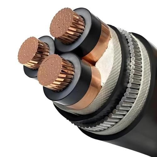
Medium-voltage underground cables commonly use engineered insulation such as cross-linked polyethylene or ethylene propylene rubber. Around that insulation sit semiconducting screens, metallic shields or concentric neutrals, moisture barriers where specified, and outer jackets selected for abrasion, corrosion, sunlight exposure at risers, and installation environment. At transitions, terminations and splices have to control electrical stress so voltage gradients do not concentrate at the insulation edge.
That is where the plant-floor comparison is useful: a good cable with a poor termination is like a well-built hydraulic hose with a bad crimp. The hose may be rated correctly, but the failure starts at the fitting. Underground power circuits behave the same way. The accessory is often where design, workmanship, and contamination meet.
Decision-relevant accessory details include:
- Terminations and stress cones: They manage the electric field where shielding ends. A nicked insulation surface or misplaced stress control component can become a partial-discharge site.
- Joints and splices: They must restore insulation, shielding, moisture sealing, and mechanical continuity. A splice is not just a connector covered in tape.
- Elbows and separable connectors: Common in pad-mounted distribution equipment, they need correct current rating, interface class, lubrication practice, and torque.
- Cable preparation: Concentric neutral cutting, semicon removal, insulation shaving, cleaning, and dimensional control matter more than non-specialists expect.
- Bend radius and pulling tension: Damage can be built into the cable during installation and appear later as an unexplained failure.
- Installer qualification: The best material package cannot fully compensate for a crew working in mud, rain, poor lighting, or under a restoration deadline without proper tools.
Medium-voltage accessory quality is one reason utilities are cautious about large underground conversion programs. Overhead construction has workmanship issues too, but many defects are visible. Underground defects can remain hidden until voltage stress, moisture ingress, or load cycling turns them into a fault.
Underground power systems are maintenance-free once installed.False
Underground systems remove many weather and tree contacts, but they still require testing, records, accessory inspection, moisture control, fault location capability, and planned replacement of components such as terminations, elbows, and splices.
Civil conditions can dominate the electrical design
On paper, underground cable routing looks tidy. On a job site, the trench may run into rock, groundwater, unstable fill, old foundations, contaminated soil, drainage structures, abandoned utilities, fiber ducts, gas mains, and municipal restrictions that only allow night work. This is one reason cost spreads get wide so quickly.
Civil and geotechnical constraints that change the design include:
| Constraint | Why it matters below grade |
|---|---|
| Rock excavation | Slows production, damages tools, increases trench cost, and may force rerouting or drilling |
| High groundwater | Complicates trench stability, vault design, cable sealing, and corrosion control |
| Corrosive soils | Affects metallic sheaths, neutrals, grounding systems, and hardware selection |
| Frost depth | Influences burial depth, conduit movement, and surface restoration durability |
| Unstable or unknown fill | Raises settlement risk and can stress ducts, joints, and vaults |
| Contaminated sites | Adds handling rules, disposal cost, worker protection, and schedule uncertainty |
| Existing utility congestion | Limits spacing, increases strike risk, and reduces room for joint bays or vaults |
| Bridge, rail, and highway crossings | Bring permitting, vibration, access, thermal, and outage-window constraints |
Directional drilling can reduce surface disruption, but it is not a magic wand. Bore path accuracy, drilling fluid management, pullback tension, unknown obstructions, and thermal performance inside the installed conduit all need review. I have seen teams love trenchless methods during planning and then quietly redesign after the utility locate marks, potholing, and bore logs made the risk obvious.
Urban underground work also lives by access windows. A downtown feeder replacement may be electrically simple but commercially painful because traffic control, police details, business access, bus routes, and pavement restoration dictate the construction rhythm. The cable is only one line item in a much larger street surgery.
Fault location and maintenance require different tools
Overhead circuits are easy to patrol compared with buried circuits. Crews can inspect poles, conductors, crossarms, switches, insulators, and tree contact from the ground, from bucket trucks, or with drones. Thermal imaging can find bad connections before failure, and storm damage is often visible as soon as the road is open.
Underground faults are located through records and instruments before anyone digs. Common practices include:
- Sheath or jacket integrity testing to find damage to protective layers
- Very-low-frequency testing for certain cable commissioning and maintenance programs
- Partial discharge assessment where the owner has the equipment, access, and reason to use it
- Time-domain reflectometry and other fault-location methods to estimate distance to a defect
- Manhole, vault, and pad-mounted equipment inspection
- Phase identification and switching verification before repair work
- Record checking against as-built drawings, GIS data, and field markers
The record discipline matters. If as-builts are wrong, if a splice location was never updated, or if a duct bank has abandoned cables mixed with energized ones, restoration slows and safety risk rises. A pole-line repair may need a new crossarm, fuse, cutout, or conductor section. An underground repair may need excavation permits, cable identification, de-energization planning, confined-space procedures, pumping, shoring, a splice kit, a qualified splicer, and enough spare cable length to work with.
The trade-off is fewer routine interruptions from wind, trees, ice, and vehicle impacts versus potentially longer repair duration when a fault does occur. That trade-off can be very favorable for some suburban feeders and critical campuses. It is less attractive where soil access is poor, documentation is weak, or the owner does not maintain splicing and test capability.
High-voltage transmission is a separate class
Distribution undergrounding and transmission undergrounding should not be priced or engineered as the same problem. High-voltage transmission cables are larger, more thermally constrained, and much less forgiving of route details. The cable system may require long pulling calculations, large vaults or joint bays, special bonding and grounding arrangements, surge protection, sheath voltage control, and detailed outage sequencing.
At transmission voltages, charging current and reactive power become major design issues, especially over longer AC cable runs. The cable’s capacitance is far higher than an overhead line’s, so the system may need reactive compensation and careful protection coordination. Thermal bottlenecks at joints, crossings, duct banks, tunnels, bridge attachments, or congested substations can set the rating for the entire line. In some installations, forced cooling is considered, but that adds pumps, heat exchangers, controls, redundancy, and maintenance obligations.
This is why utilities may underground a short transmission segment through a constrained urban corridor but resist burying long rural transmission routes. The engineering problem is not only “can the cable be insulated?” It is whether the complete system can carry the required load, reject heat, manage reactive effects, be repaired within acceptable outage windows, and justify the capital cost over its service life.
Permits, ownership, and incentives
Undergrounding moves slowly in the United States because the decision is rarely owned by one party with one budget. A city may want cleaner streets, a utility may control the wires, a regulator may control cost recovery, and the property owner may control the land needed for transformers, vaults, or service changes. Even when the engineering case is sound, the institutional case has to survive permits, easements, rate hearings, funding rules, and construction sequencing.
The American grid is not a single public works department. Along one feeder route, several parties can have a legitimate say:
- Investor-owned utilities, which usually recover approved investment through regulated rates.
- Municipal utilities, where the city or local authority owns the electric system and answers to local boards or elected officials.
- Rural electric cooperatives, which serve wide, lower-density areas where per-mile economics are especially sensitive.
- Transmission owners, which may be separate from the local distribution utility.
- Distribution operators, who deal with poles, pad-mounted gear, service laterals, switching, outage restoration, and customer conversions.
- Independent system operators or regional transmission organizations, which may influence transmission planning and interconnection work, though they do not decide every neighborhood distribution project.
- Developers and homeowners’ associations, especially in new subdivisions where underground service is often built into the site plan from day one.
- Property owners, who may need to grant easements or accept pad-mounted equipment.
- Public agencies, including highway departments, rail authorities, drainage districts, coastal commissions, parks departments, and historic preservation offices.
That fragmentation creates a practical problem I have seen on many infrastructure jobs: the group receiving the most visible benefit is not always the group paying the bill, taking the outage risk, or maintaining the asset for the next 40 years.
Utility commissions do not approve “nice to have” spending casually
For investor-owned utilities, large undergrounding programs often pass through public utility commission review. The utility normally has to show that the investment is prudent, cost-effective, and allocated fairly among ratepayers. That is a hard case when a conversion benefits a beach town, a wooded ridge, or a wealthy subdivision more directly than the rest of the service territory.
Regulators tend to ask uncomfortable but necessary questions:
- Does undergrounding this circuit reduce total system outage risk enough to justify the capital cost?
- Are customers outside the project area being asked to subsidize a local aesthetic improvement?
- Would vegetation management, covered conductor, pole hardening, reclosers, sectionalizers, or targeted feeder automation produce more reliability per dollar?
- How will future repair costs be handled if underground faults require excavation, traffic control, or specialty splicing crews?
- Is the project part of a broader resilience plan, or is it a one-off political request?
That does not mean commissions oppose undergrounding. It means broad conversion programs need a record that holds up under public review. The mechanism is simple: once the investment enters the regulated asset base, customers pay for it through rates over time. If only a small district receives the direct benefit, the fairness argument becomes just as important as the engineering argument.
Undergrounding decisions in the U.S. are often delayed by ownership, permitting, easement, and cost-allocation issues, not only by cable technology.True
Underground cable systems are technically feasible, but approval and execution commonly require coordination among utilities, regulators, municipalities, property owners, and public agencies. Cost recovery and benefit allocation can be contested, especially for broad distribution conversion programs.
Cities can require underground utilities, but they still need a funding path
Municipal authority is strongest in new construction. A city can require underground utilities in a new subdivision, downtown streetscape project, redevelopment district, scenic corridor, or coastal resilience zone. That is why many newer American neighborhoods have underground service while older areas nearby still have pole lines.
Retrofit work is harder. The existing overhead route already has poles, attachments, service drops, streetlights, communications cables, and easements. A city that wants conversion may need one or more funding mechanisms:
- Special assessment districts charged to benefiting properties.
- Local improvement districts.
- Municipal bonds.
- Tax increment financing in redevelopment areas.
- Utility tariff riders approved by a regulator.
- Developer contributions tied to rezoning or site approval.
- State or federal grants for resilience, transportation, or hazard mitigation.
The trade-off is political as much as technical. Local funding gives a city more control and makes the beneficiary-pay argument cleaner, but it can trigger property owner resistance. Utility-wide funding spreads the cost, but it invites regulatory scrutiny from customers who may never see a single pole removed from their street.
Easements and access are often the hidden schedule killer
Overhead lines can often follow long-established rights-of-way. They may not be pretty, but the access pattern is known: bucket truck, pole line, road shoulder, alley, rear-lot easement, or transmission corridor. Underground conversion changes the physical footprint.
A conversion may require:
- New easements for underground duct banks or direct-buried cable.
- Locations for pad-mounted transformers, switchgear, junction cabinets, and sectionalizing equipment.
- Vaults or manholes in dense urban areas.
- Service entrance modifications at each building.
- Trenching through driveways, sidewalks, landscaped yards, parking lots, or tree roots.
- Coordination with water, gas, sewer, telecom, storm drains, traffic signals, and street lighting.
- Permanent access rights for future fault repair and equipment replacement.
That last item is not paperwork trivia. A pad-mounted transformer behind a locked gate, a splice vault under a newly poured decorative plaza, or a duct bank squeezed beside an unmarked irrigation main will punish the maintenance crew later. Good underground design needs access discipline: enough room to work, safe switching positions, clear cable pulling routes, and restoration plans that do not depend on heroic field improvisation.
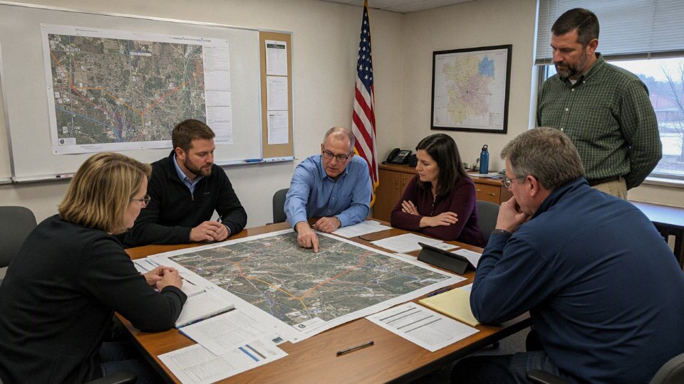
Incentives do not line up neatly
Homeowners usually value fewer local storm outages, better views, and no trees trimmed into odd shapes around wires. Utilities are judged on systemwide reliability, safety, capital efficiency, restoration time, and regulatory approval. Emergency managers may care less about neighborhood appearance and more about hospitals, pumping stations, evacuation routes, military facilities, communications hubs, and traffic corridors.
Those incentives can point to different answers. A utility engineer may recommend undergrounding only the worst-performing lateral serving a fire station and a water plant, while residents want the entire scenic road converted. A regulator may approve targeted hardening in wildfire country but reject a broad aesthetic program. A city may support undergrounding downtown because street reconstruction is already scheduled, while the same project would be uneconomic if the pavement had to be opened only for electric work.
Federal or state resilience money can shift the calculation. Grants or cost-share programs may make undergrounding more attractive in wildfire exposure zones, hurricane-prone coastal areas, critical infrastructure corridors, military bases, hospital districts, evacuation routes, and grid modernization projects. The funding does not make the work cheap; it changes who carries the capital burden and which benefits count in the approval file.
Approval is not the same as energization
Even after a project is approved, the field schedule can stretch for years. Design has to be completed, permits secured, materials specified, cable and accessories procured, outage windows negotiated, civil crews scheduled, customers converted, old overhead facilities removed, and the new system tested and commissioned.
Materials alone can become a gating item. Underground work is not just cable on a reel. It includes terminations, elbows, joints, separable connectors, ducts, pulling lubricant, vault hardware, grounding materials, pad-mounted equipment, protective devices, and sometimes specialty monitoring or communication equipment. Long-lead switchgear or transformers can hold up an otherwise straightforward conversion. Anyone who has had a crew waiting on one missing connector kit knows how quickly a clean schedule turns into expensive idle time.
The main boundary is this: institutional delay matters most for retrofit projects crossing public streets, multiple properties, or regulated cost recovery. In a new private development with a single owner, clear utility standards, and coordinated civil works, underground construction can move much faster because the easements, trenching, service locations, and funding model are settled before the first curb is poured.
Where undergrounding wins
Undergrounding wins where the route is short, the load or consequence is high, the civil work is already open, or overhead construction creates unacceptable risk, clearance, or land-use conflict. It is rarely the cheapest way to move electrons, but it can be the best value when avoided outages, avoided pole conflicts, fire-risk reduction, streetscape value, or customer criticality outweigh the higher installed cost.
The strongest case is often a new residential subdivision. Before asphalt, curbs, sidewalks, driveways, irrigation, fences, and lawns are in place, the developer and utility can trench once, install ducts, pull cable, set pad-mounted transformers, and run service laterals without tearing up finished property. The cost is still higher than simple pole-line construction, but the timing changes the economics: restoration is minimal, easements are clean, and the same civil contractor may already be mobilized for water, sewer, telecom, and street lighting. In a finished neighborhood, the same job becomes a traffic-control, landscaping, driveway-repair, customer-access headache.
Dense urban centers are the other obvious fit. Pole space is limited, load density is high, and a single block may carry electric distribution, telecom, streetlights, signs, traffic signals, and building services in a messy overhead bundle nobody wants to own. Underground construction costs more, especially with unknown utilities, old vaults, steam lines, and night-work requirements, but the asset serves many customers per mile. Pedestrian safety, truck clearance, streetscape projects, and fire access also matter. In practice, city work succeeds or fails on coordination: if the electric utility opens the street six months after a water-main replacement, everyone pays twice.
Undergrounding is most economically defensible where trenching is combined with other planned civil work or where customer load density is high.True
The fixed costs of excavation, traffic control, restoration, duct banks, vaults, and coordination are spread across more customers or shared with other construction scopes. This does not make every urban or subdivision project cheap, but it improves the cost-benefit case compared with retrofitting long rural routes.
Critical facilities deserve separate treatment because the value of continuity is not the average residential bill. Hospitals, data centers, airports, ports, military bases, universities, semiconductor plants, transit hubs, water treatment plants, and emergency operations centers may justify underground feeders, looped service, redundant routes, protected switchgear, and on-site generation interfaces. The engineering goal is not just hiding the wire; it is controlling failure modes. A buried feeder protected from trees is useful, but if both feeders enter the same flooded vault or share one duct bank under a loading dock, the plant has paid for neatness rather than resilience.
The better design is usually selective: underground the exposure that creates the unacceptable consequence, then verify that switching, protection, drainage, access, and spare-parts strategy support the same reliability objective. Data centers and fabs are good examples. They may accept high feeder construction cost because process interruption, product loss, restart time, and contractual penalties dwarf the civil premium. A municipal park building usually cannot make the same case.
Wildfire-risk corridors are increasingly strong candidates for targeted undergrounding, especially where bare overhead conductors run through vegetation-dense, windy, difficult-to-patrol terrain. The mechanism is direct: remove energized conductors from tree contact, wind-driven galloping, broken crossarms, and pole-top hardware failures, and ignition exposure drops for that segment. The trade-off is that underground cable still needs terminations, cabinets, protection devices, and access roads; it also introduces excavation disturbance and longer repair windows after a fault. The case weakens where terrain is rocky, environmentally sensitive, unstable, or so remote that construction and maintenance access become a second risk.
Coastal and hurricane-prone neighborhoods can also benefit, but they are not automatic wins. Underground circuits avoid wind-blown debris, falling palms, and snapped poles, which are common failure points in severe storms. The catch is water. Pad-mounted transformers, switch cabinets, splice boxes, and vaults must be placed above expected flood levels or built with suitable drainage, sealing, corrosion protection, and safe re-energization procedures. Saltwater intrusion is especially unforgiving; after storm surge, equipment that looks intact may still be contaminated internally. Aerial lines may be ugly, but a flooded padmount on every corner is not resilience.
Scenic, heritage, and high-value commercial districts often justify undergrounding for reasons that are partly commercial rather than purely electrical. Tourism streets, historic downtowns, waterfront promenades, resort zones, medical districts, and premium retail corridors may place a measurable value on unobstructed views, outdoor dining space, sign visibility, property frontage, and public-realm quality. That value usually comes from a city, developer, improvement district, or special assessment mechanism, not from the utility’s reliability budget alone.
Short, high-consequence crossings are another practical category:
- Road widenings where poles would conflict with clear zones, turn lanes, or sidewalks.
- Rail crossings where overhead clearance, ownership, and outage windows are hard to manage.
- River or canal crossings where pole structures are impractical or visually unacceptable.
- Airport approaches where height restrictions remove overhead options.
- Industrial sites with cranes, tall loads, pipe racks, or frequent truck movements.
- Constrained rights-of-way where easement width cannot support safe pole placement.
These projects are expensive per foot, but the alternative may be no buildable overhead route at all.
Selective hardening programs are usually the most commercially disciplined version of undergrounding. Utilities review outage history, vegetation exposure, customer count, critical loads, patrol difficulty, and repair access, then underground the worst-performing feeder taps or mainline segments instead of an entire service territory. That approach does not create a “storm-proof” grid, and it will not eliminate underground faults, animal damage at cabinets, or vehicle strikes on pad-mounted equipment. It does, however, put capital where the reliability benefit per dollar is most defensible.
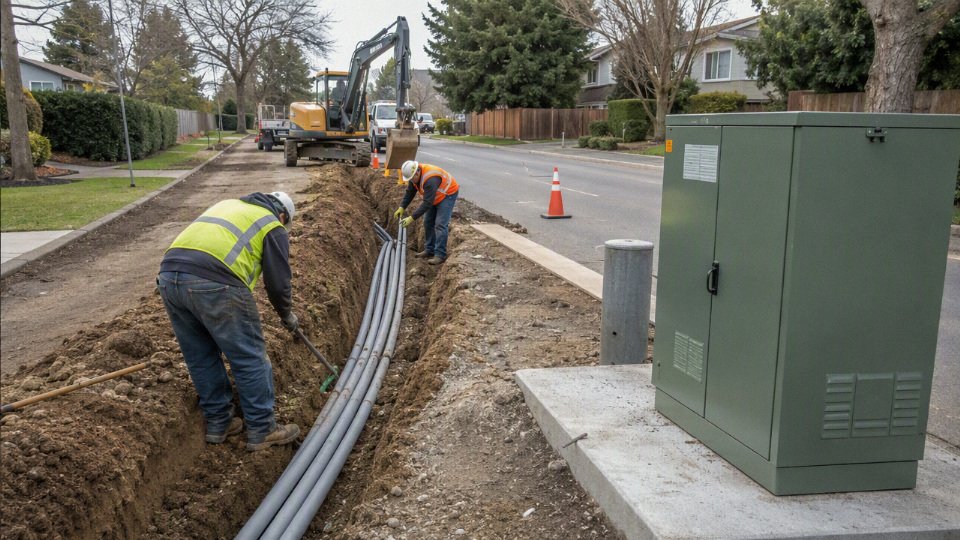
Cable and procurement requirements
For an underground power project, the cable purchase is not just a price-per-foot exercise. The procurement package has to match the electrical duty, soil and duct conditions, utility standards, accessories, test regime, delivery schedule, and repair strategy for the next several decades. A cheap cable that is difficult to terminate, trace, test, or repair usually becomes expensive after the trench is closed.
Main cable categories in underground power work
Underground systems use several cable families, and mixing them loosely in a bill of materials is where procurement trouble starts.
- Low-voltage service cable
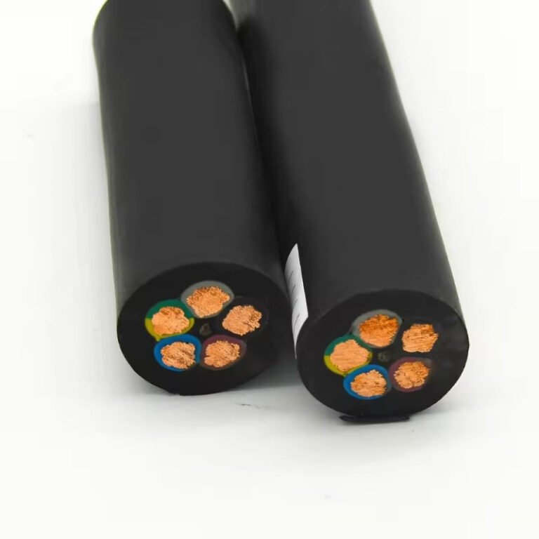
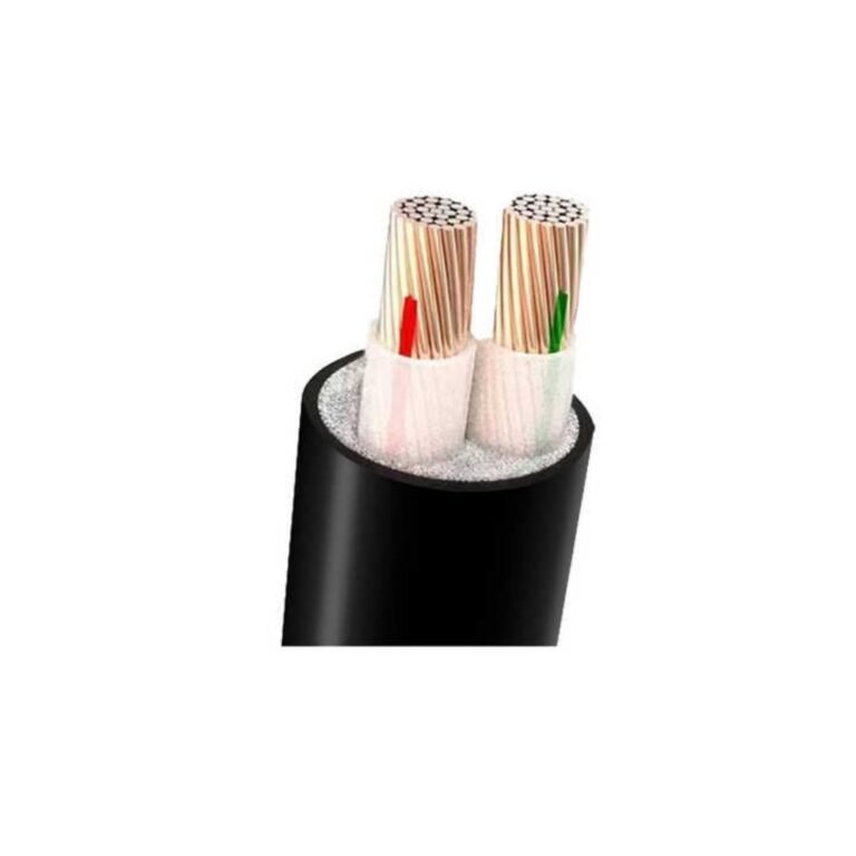
Used from secondary transformers to homes, shops, meters, panels, and small facilities. The buyer still has to define conductor size, neutral arrangement, insulation, jacket, burial or duct rating, and local code requirements. - Medium-voltage primary distribution cable
This is the common underground feeder class for utility distribution and large private networks. It usually needs a shielded insulation system, compatible terminations and joints, clear test documentation, and careful pulling controls. High-voltage underground cable
Used for transmission or sub-transmission routes. These projects require much tighter design coordination because thermal limits, sheath bonding, joint bays, installation method, and commissioning tests can dominate both cost and schedule.Control cable
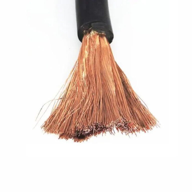
Used for switchgear control, relay circuits, interlocking, auxiliary power, and signaling. It may not carry high power, but poor shielding, weak jacket selection, or unclear core identification can create very expensive troubleshooting.Grounding conductors and bonding leads
These are part of the safety and fault-current system, not just “extra copper.” Size, corrosion protection, connection method, and compatibility with shields, screens, rods, grids, and enclosures must be defined.Communication cable for grid automation
Fiber optic or copper communication cables support fault indicators, reclosers, sensors, SCADA, and remote switching. They need the right crush resistance, moisture protection, pulling specification, and sometimes separation from power circuits.Specialty cables for industrial or harsh environments
Refineries, ports, mines, tunnels, chemical plants, rail corridors, renewable substations, and flood-prone sites may need oil resistance, UV resistance, flame performance, low-smoke materials, rodent protection, armor, or enhanced water blocking.
Specification variables that decide whether the cable fits the route
The specification should be built from the installation outward, not copied from the last project. In practice, I want the route drawings, duct bank detail, soil condition, pulling plan, switchgear interface, and utility standard on the table before finalizing the cable schedule.
| Specification item | Why it matters in procurement |
|---|---|
| Voltage rating | Sets the insulation system and compatibility with the network operating voltage and overvoltage conditions. |
| Conductor material | Copper reduces size and losses but costs more; aluminum is common for distribution where larger cross-section and termination practice are acceptable. |
| Conductor size | Affects ampacity, voltage drop, fault duty, pulling weight, drum size, and installed cost. |
| Insulation type and level | Determines electrical performance, thermal rating, aging behavior, and suitability for grounded or resistance-grounded systems. |
| Metallic shield or screen design | Controls electric field, fault current path, grounding method, and accessory compatibility. |
| Water-blocking features | Reduces longitudinal moisture migration if the jacket is damaged or water enters a duct. |
| Armor or jacket | Protects against mechanical damage, chemicals, sunlight during storage, rodents, or direct burial conditions. |
| Flame performance | Required in tunnels, buildings, stations, and some industrial areas depending on local rules and owner standards. |
| Temperature rating | Drives ampacity calculations and allowable emergency loading. |
| Short-circuit rating | Must survive fault current until protection clears, including conductor and shield performance. |
| Bend radius | Limits drum handling, duct entry geometry, manhole layout, and termination space. |
| Pulling tension | Controls installation method, winch settings, sidewall pressure, and risk of conductor or insulation damage. |
| Installation environment | Direct burial, duct, tray, tunnel, wet vault, rocky trench, contaminated soil, or marine exposure all change the cable design. |
The mechanism is simple but unforgiving: underground cable depends on insulation integrity and heat dissipation, while overhead conductors rely more on air clearance and ambient cooling. If the jacket is damaged during pulling, moisture can enter; if the insulation is eccentric, the electric field becomes uneven; if the shield is poorly designed or badly terminated, partial discharge and heating risks rise. None of those defects announces itself like a broken pole arm. The first sign may be a feeder trip on a wet night three years later.
The trade-off is that a more robust cable design may increase purchase price, drum weight, bend radius, and installation effort. The preference flips when the route has difficult access, high outage penalties, long repair times, or expensive civil works. Saving a few percent on cable makes little sense if a later failure requires lane closures, excavation permits, night work, and emergency splicing.
Documentation and supplier qualification
International cable procurement needs paperwork that is useful, not just thick. Buyers should request:
- Applicable standards used for design, manufacturing, testing, marking, and packaging.
- Routine test reports for the production lots being supplied.
- Type test evidence for the relevant cable design, voltage class, and construction.
- Factory inspection records or agreed inspection and witness points.
- Material and production traceability, including batch or drum identification.
- Packaging details, including drum construction, flange protection, sealing, and lifting points.
- Drum lengths and length tolerance, matched to pull sections and joint locations.
- Installation handling instructions, including minimum bend radius, pulling tension, storage limits, and approved pulling practices.
- Customs and shipping documentation, especially for cross-border projects with phased deliveries.
- After-sales technical support arrangements, so site questions do not sit unanswered while a crew and crane are waiting.
For buyers outside the manufacturer’s home market, standards alignment matters because utility practice is not identical from country to country. A cable that is acceptable in one network may need different marking, fire behavior, conductor class, shield construction, or test evidence for another. Shandong Jinda Special Cable Group Co., Ltd., established in 1987, is positioned as a manufacturer with multiple production bases in China, integrated research and development, production, sales, technical support, and after-sales service; that kind of structure is useful when a developer, EPC contractor, or utility buyer needs factory coordination rather than a spot-market cable shipment.
Quality risks that show up after installation
The expensive failures are often created before the cable arrives on site. Common procurement and manufacturing risks include:
- Eccentric insulation, which creates localized electrical stress.
- Poor metallic shield or screen contact, which can interfere with grounding, fault current flow, and accessory performance.
- Jacket cuts, scuffs, or pinholes, especially if shipping protection is weak or reels are dragged around a yard.
- Moisture pathways, including weak end sealing, inadequate water blocking, or damaged jackets.
- Inadequate compound selection for heat, oil, chemicals, sunlight, or wet ducts.
- Inconsistent conductor geometry, which can affect extrusion quality, termination fit, and electrical stress distribution.
- Weak accessory compatibility, where the cable nominally meets the voltage rating but does not fit the selected joints, lugs, glands, elbows, or separable connectors cleanly.
- Insufficient factory testing, leaving the site team to discover defects during commissioning or, worse, after energization.
Accessory matching deserves its own procurement review. Cables must be confirmed against the project owner’s approved joints, terminations, separable connectors, lugs, glands, ducts, pulling lubricants, grounding hardware, and commissioning test methods. I have seen good cable installations slowed down by something as mundane as a lug barrel mismatch or a termination kit that was correct by voltage class but wrong for insulation diameter. That is not an engineering triumph; it is a purchase order gap.
Bulk procurement and site logistics
Bulk underground cable is heavy, awkward, and easy to damage through careless handling. The procurement plan should specify drum design, shipping protection, flange strength, weatherproofing, lifting method, end sealing, and storage conditions. On site, drums should sit on prepared ground, not half-sunk in mud behind the substation fence with the end caps missing.
Phased delivery also needs discipline. Long lead items may include high-voltage cable, special compounds, armored constructions, large drums, factory-tested accessories, or export documentation. Lot traceability should connect each drum to factory records, shipping papers, receiving inspection, pull location, and test results. If a defect or handling issue appears, traceability lets the owner isolate risk instead of treating the whole shipment as suspect.
Undergrounding only works commercially when the cable system is procured as a matched package: cable, accessories, documentation, logistics, and technical support. The boundary is clear: final cable selection still has to be verified against the utility standard, local code, route thermal study, installation method, and current supplier documentation before release for manufacturing.
Frequently asked questions
Can all power lines technically be buried?
Many distribution lines can be placed underground, but “can” does not mean “should” or “can be done without major system work.” The hard limits usually come from:
- Rock, high groundwater, unstable soil, or contaminated ground
- Limited access for trenching, duct banks, splice vaults, and pulling equipment
- Heat dissipation limits under heavy electrical loading
- Higher voltage levels that require larger insulation systems and more engineered joints
- Environmental permits around wetlands, waterways, tree roots, and protected corridors
- The need to keep customers energized while the old overhead route is converted
Transmission circuits are a different class of problem. Undergrounding them may require special cable systems, joint bays, reactive power compensation, thermal studies, and outage planning that can be harder than the civil work itself.
Why does Europe seem to have more underground power lines?
Europe often has denser settlement patterns, shorter urban route lengths, older compact city layouts, and planning rules that make underground distribution easier to justify. Some areas also rebuilt or modernized networks under different postwar, municipal, or national infrastructure policies than many U.S. utilities.
That said, Europe still uses overhead lines extensively, especially for high-voltage transmission and rural feeders. The comparison is not “Europe buries everything and America does not”; it is more a difference in density, land-use history, regulatory choices, and who pays for public works.
Are underground power lines safe in floods?
They can be designed for wet environments, but flooding is still a serious operating condition. The cable itself may tolerate moisture if specified and installed correctly, while vaults, terminations, pad-mounted transformers, switchgear, and control wiring are often the weak points.
After a flood, utilities may need to inspect for:
- Water intrusion in vaults and cabinets
- Damaged seals or terminations
- Corrosion on grounds, connectors, and enclosures
- Silt blocking drainage paths
- Unsafe energized equipment in public areas
A flooded underground system is not automatically failed, but it is not something a crew should re-energize casually.
Do underground lines prevent blackouts?
No. Undergrounding reduces outages from trees, wind, ice loading, vehicle strikes, and some wildfire exposure, but it does not prevent every blackout mechanism.
Blackouts can still come from generation shortages, substation failures, transmission bottlenecks, relay misoperations, cyber events, aging equipment, heat-driven overloads, or regional disasters. Undergrounding changes the risk profile; it does not make the grid immune.
Underground power lines reduce some outage causes, but they do not eliminate blackouts.True
They are less exposed to wind, trees, ice, and vehicles, but failures can still occur in substations, generation, transmission networks, controls, and underground cable accessories.
Can homeowners request underground service?
Often, yes, especially for a service lateral from a pole or pad-mounted transformer to a house. Local rules vary, but the homeowner, developer, homeowners association, or improvement district usually pays the incremental cost unless a utility program or public project covers it.
Expect the utility to control the design requirements: conduit size, burial depth, meter location, easements, transformer access, inspection steps, and approved contractors. A neat trench in the wrong place is still a failed installation if the utility cannot maintain it safely.
Do underground cables last longer than overhead lines?
They can have long service life, but it is not automatic. Life depends on cable design, insulation type, loading history, moisture control, soil thermal conditions, pulling damage, splice workmanship, terminations, and maintenance of vaults or pad-mounted equipment.
In practice, many underground failures are not in the straight cable length; they are at joints, terminations, damaged sections, or accessories exposed to water and thermal cycling. Good cable procurement matters, but installation quality and route conditions matter just as much.
Are covered overhead conductors the same as underground cables?
No. Covered overhead conductors have an outer covering that can reduce some contact risks from branches, wildlife, and momentary incidental contact, depending on the design. They are still overhead conductors and are not built to operate continuously in soil, ducts, submerged vaults, or direct-burial conditions.
Underground power cables require a different insulation system, metallic shielding or concentric neutral arrangement, moisture protection, fault-current path, jacket design, and accessories. Treating covered overhead wire as if it were underground cable would be a serious specification error.
Verify your undergrounding case
Do not start with “overhead versus underground” as a general argument; start with the route. A half-mile feeder through a hospital district, a wooded fire-prone ridge, and a rocky rural road can produce three completely different answers even at the same voltage class.
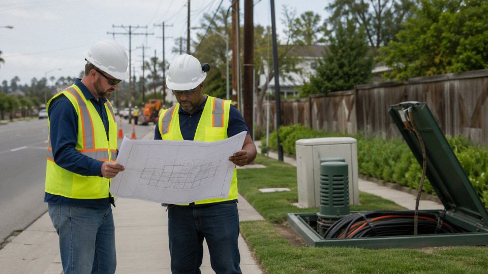
Build the first screen around the actual corridor, not the preferred outcome:
- Load and voltage class: peak load, future load growth, feeder role, and whether the project is distribution, sub-transmission, or transmission.
- Customer criticality: hospitals, water plants, data centers, industrial processes, traffic systems, and emergency services deserve different outage economics than low-density residential laterals.
- Outage history: separate tree contacts, wind, ice, vehicle strikes, equipment failure, flooding, and animal damage. Undergrounding fixes some causes and leaves others untouched.
- Soil and water conditions: thermal resistivity, rock, corrosive soil, groundwater, seasonal flooding, and contaminated excavation can change both ampacity and installed cost.
- Wildfire and storm exposure: undergrounding may be compelling where overhead ignition risk or repeated tree damage dominates.
- Existing utilities: gas, water, telecom, sewers, drainage, and old undocumented services can turn a clean drawing into slow potholing and field redesign.
- Restoration and easements: pavement restoration, traffic control, landscaping, private crossings, railroad permits, and available right-of-way often decide whether the schedule is realistic.
The commercial check should be blunt. Compare new-build versus retrofit cost, because trenching in an open subdivision is not the same job as cutting through a finished downtown street. Then test the case against:
- customers served per mile;
- avoided outage cost, including spoiled production, emergency generation, and crew callouts;
- avoided vegetation management;
- property value, streetscape, or redevelopment benefit;
- grant or resilience funding;
- rate recovery rules;
- construction disruption to businesses, residents, and traffic.
The engineering review has to run in parallel, not after the budget is approved. Confirm ampacity, thermal resistivity assumptions, duct bank arrangement, cable insulation system, jointing plan, grounding and bonding, protection coordination, equipment elevation above flood risk, acceptance testing, and repair access. A design that looks economical on cable price alone can become expensive if joint bays are missing, pulling tensions are unrealistic, or the accessories are specified after the ducts are already in the ground.
Bring the utility, civil engineer, electrical designer, cable manufacturer, accessory supplier, and installation contractor into the discussion early. In practice, the costly mistakes are rarely exotic: incompatible terminations, duct sizes that do not match pulling plans, unclear standards, missing spare ducts, or delivery dates that do not fit the outage window.
For underground cable projects, bulk procurement, or international supply planning, Jinda can support a technical review or quotation when the buyer provides route data, voltage class, applicable standards, estimated quantity, installation method, required delivery schedule, and any known soil, water, or thermal constraints. Clear drawings, load data, and site photos make the first review much more useful than a cable size request alone.