Underground cables look clean on a drawing, but the problems start when the route meets rock, congested utilities, wet soil, road reinstatement, and future fault access. A defect that would be visible on an overhead line can turn into fault location, excavation, jointing, testing, and surface repair. That is where the budget moves from “higher installation cost” into outages, emergency crews, traffic control, and procurement decisions that must be made correctly before the trench is closed.
The main disadvantages of underground cables are high installation cost, slower fault repair, difficult inspection, heat dissipation limits, route-access constraints, and expensive modification. Compared with overhead lines, underground installation commonly costs 2 to 10 times more, and repair can take many hours to several days depending on location and fault type.
None of that means underground cable is a bad choice. In dense cities, industrial parks, ports, campuses, and areas with severe weather exposure, it may still be the better engineering decision. The question is not “overhead or underground” in the abstract; it is whether the soil, load profile, route, maintenance plan, and project budget can carry the disadvantages without creating trouble five years later.
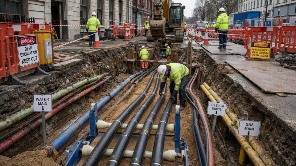
Capital cost penalties
Underground cable projects commonly cost several times more than comparable overhead routes, and the cable price is only one slice of that penalty. A useful planning range is roughly 2 to 10 times overhead construction, but the multiplier depends heavily on voltage level, trenching method, reinstatement requirements, ground conditions, and how crowded the route is with existing utilities.
The first procurement mistake I see is comparing “cable per meter” against “overhead conductor per meter” and thinking the difference explains the project budget. It does not. Undergrounding is a system purchase: engineered cable, accessories, civil works, testing, installation control, and surface restoration all have to function together.
A realistic cost stack usually includes:
- Cable design and materials
- Conductor material and cross-section
- Insulation system, such as XLPE or other specified insulation
- Metallic screen, concentric neutral, lead sheath, aluminum laminate, or other moisture barrier where required
- Outer sheath material matched to soil chemistry, pulling conditions, and termite or hydrocarbon exposure
- Armor for direct-buried routes, industrial campuses, mining areas, or mechanically exposed sections
- Installation materials
- Ducts, conduits, or HDPE sleeves
- Concrete duct banks where mechanical protection or multi-circuit routing is needed
- Thermal backfill, sand bedding, selected fill, warning tape, marker tiles, route markers
- Cable cleats, supports, pulling eyes, lubricants, rollers, and temporary works
- Accessories and network hardware
- Straight joints, transition joints, branch joints, and joint bays
- Terminations, sealing ends, stress control kits, surge arresters where specified
- Link boxes, sheath bonding leads, cross-bonding hardware for higher-voltage systems
- Earthing materials and test points
- Project execution
- Excavation, shoring, dewatering, directional drilling, thrust boring, or road cutting
- Traffic management, night-work premiums, permits, utility shutdown coordination
- Surface reinstatement: asphalt, concrete slab, paving blocks, landscaping, rail corridor repair
- Specialist jointers, cable-pulling crew, site supervision, commissioning tests
Underground cable installation is commonly 2 to 10 times more expensive than comparable overhead construction.True
This is a practical planning range, not a universal quote. The actual multiplier depends on voltage, route length, excavation method, reinstatement, congestion, labor market, and local permitting conditions.
In open rural ground, the civil package may be manageable: trench, bedding, cable, backfill, marker tape, test, reinstate. In a city street or operating plant, the same meter of route can become a small construction project. You may be cutting reinforced concrete, maintaining vehicle access, crossing steam lines and drains, working around unknown legacy cables, and paying crews to stand by while a permit window opens. On industrial sites, I have seen the “simple” route change because nobody wanted to shut down a pipe bridge area or disturb a firewater main that was not shown correctly on the drawing.
Voltage level changes the economics sharply. Low-voltage and some medium-voltage underground runs are often acceptable for short feeders, building connections, renewable plant collection circuits, and internal factory distribution, especially where overhead lines would interfere with cranes, roads, or future buildings. The cable is more expensive than overhead conductor, but the installation remains within normal contractor capability if the route is short and accessible.
At medium voltage, the accessory and testing burden starts to matter more. Joints must be made cleanly and consistently. Terminations need correct stress control, moisture sealing, and earthing. Sheath testing, VLF or withstand testing where applicable, and partial discharge testing may be specified depending on the project standard and voltage class. None of these is exotic, but they add labor, schedule control, and quality risk.
High-voltage and extra-high-voltage undergrounding is a different financial animal. Insulation thickness, metallic sheath design, bonding arrangement, thermal modeling, pulling tension limits, joint bay design, and installation cleanliness become major cost drivers. The cable may require special drums, route-specific lengths, factory acceptance tests, and more formal installation supervision. A small error in sheath bonding or joint workmanship can turn into a very expensive outage later, so the project pays for controls before the cable ever carries load.
The physical mechanism behind much of the added cost is heat. Underground cables reject heat through insulation, sheath, bedding, duct or soil, then outward into surrounding ground. If soil thermal resistivity is poor, ducts are crowded, burial depth is high, or circuits are bunched too tightly, ampacity falls. To carry the same load, the designer may need:
- A larger conductor
- Parallel cables per phase
- Wider cable spacing
- Thermal backfill
- A ventilated or engineered cable tunnel
- A longer route to avoid hot spots or utility congestion
That is why a cheaper cable construction can raise the installed project cost. A smaller conductor or lower-cost sheath may look attractive in a bid table, but if it forces extra trenches, more circuits, more joints, reduced loading margin, or a shorter service life, the saving disappears into civil work and outage risk. The preferred choice flips only when the route is short, thermally benign, mechanically protected by design, and the load profile is well understood.
Hidden procurement costs also deserve a line in the budget before tendering, not after award:
- Route survey and constructability review
- Geotechnical investigation for rock, groundwater, corrosive soil, and thermal resistivity
- Third-party utility mapping and trial pits
- Special drum sizes, transport permits, unloading plans, and storage space
- Factory acceptance tests specified by the buyer or utility
- Sheath integrity testing and after-laying tests
- Partial discharge testing where technically justified
- Installation method statements and manufacturer or specialist supervision
- Spare cable lengths, spare joints, and emergency repair strategy
Cost control is not the same as buying the cheapest cable. The better route is to specify accurately, standardize cable sizes where practical, reduce unnecessary joint counts, and match armor, sheath, and moisture protection to actual hazards rather than worst-case imagination. Early discussion with the cable manufacturer can also prevent awkward procurement gaps: drum length versus pulling length, bending radius versus manhole size, sheath design versus bonding plan, and conductor size versus soil conditions.
The boundary is clear: underground cost penalties are most severe where routes are congested, thermally constrained, heavily reinstated, or high voltage. Where the run is short, access is easy, and the avoided cost of outages, land use, visual impact, or mechanical exposure is high, underground cable can still be the correct commercial decision — but it should be priced as a complete installed system, not as a cable line item.
Civil works and route constraints
Underground cable disadvantages often start with the corridor, not the conductor or insulation system. A cable that looks straightforward on a single-line diagram may become difficult once the route crosses private land, congested roads, buried services, rail property, drainage lines, foundations, waterways, or an area reserved for future plant expansion.
A usable underground route needs physical access for survey, excavation, cable drum handling, pulling, jointing, testing, and later repair. That sounds obvious until the proposed alignment runs behind a building with no crane access, under a reinforced concrete yard slab, across a stormwater culvert, or through a utility corridor already packed with gas, water, fiber, and medium-voltage feeders. In practice, the “shortest route” is not always the buildable route.

Trenching is a construction job before it is an electrical job
Open trenching gives good visibility and control, but it brings all the normal civil risks onto the cable project. The crew must manage:
- Excavation depth and profile, including required cover, road authority rules, frost depth in some regions, and space for bedding and warning protection.
- Trench stability, especially in loose fill, wet clay, made ground, or near existing foundations where shoring may be needed.
- Dewatering, which can turn a planned cable pull into a mud job if groundwater, storm runoff, or a leaking service enters the trench.
- Bedding preparation, because sharp aggregate, construction debris, or uneven support can damage the sheath or create point loading.
- Safe separation from other services, including thermal separation from heat sources and physical clearance from gas, water, sewer, telecom, and existing electrical circuits.
- Minimum bending radius, which affects route geometry at corners, pit entries, joint bays, and building penetrations.
- Drum handling and pulling setup, including where the drum sits, where the winch sits, and whether forklifts, cranes, or trailers can actually reach the workface.
- Pulling tension and sidewall pressure, especially on long pulls, multiple bends, duct banks, or large cross-section cables.
The mechanism is simple but unforgiving: route geometry and duct condition translate directly into pulling force, bending stress, and sheath contact pressure. If the civil design ignores those forces, the cable can be damaged during installation while still passing a casual visual inspection. That is one of the more frustrating failure modes, because the electrical buyer may not see the consequence until testing, energization, or an early-life fault.
Trenchless methods help, but they are not magic
Horizontal directional drilling, pipe jacking, and microtunneling can avoid open cuts across roads, rivers, rail lines, and sensitive surfaces. They are valuable tools, and I would rather drill under a major road than fight a weekend closure with traffic police and a reinstatement crew. Still, trenchless work shifts the difficulty rather than removing it.
Key constraints include:
- Bore path design, allowable bend radius, and separation from existing underground assets.
- Entry and exit pit space, which can be hard to find in built-up areas.
- Duct friction, lubricant selection, and cable pulling stress control.
- Geotechnical uncertainty, including boulders, voids, old foundations, contaminated ground, or mixed strata.
- Verification of final duct position, cleanliness, mandrel testing, and water ingress control.
The trade-off is usually surface disruption versus installation uncertainty. Trenchless construction may reduce traffic impact and reinstatement work, but it can increase engineering preparation, specialist contractor dependency, and the risk of a failed bore or unusable duct. The preference flips when surface access is politically or operationally impossible, such as a rail crossing, airport road, process plant entrance, or protected wetland.
A shorter underground cable route is always the better route.False
A shorter route can be inferior if it has poor access, excessive bends, difficult utility crossings, high repair consequences, or conflicts with planned expansion. Buildability and maintainability matter as much as length.
Urban and industrial sites add operating restrictions
Dense sites impose constraints that rarely show up in a cable datasheet. Work may be limited to night shifts, short road-closure windows, shutdown weekends, or permit-controlled hot work periods. On an industrial plant, the cable route may pass near live process systems, hazardous-area classifications, fire walls, pipe racks, tank farms, or concrete bunds. Cutting a trench through an old slab can expose rebar, unknown conduits, oily soil, or legacy cables that nobody has on the latest drawing.
Industrial buyers should pay special attention to coordination with live electrical systems. A new feeder may need to cross existing high-load circuits, control cables, instrument air, cooling water, and drainage channels. If the installation blocks a fire lane, isolates a loading bay, or forces scaffold removal around running equipment, the cable job becomes a production-risk discussion, not just a procurement package.
Permits and stakeholders can control the schedule
Civil-route approval often takes longer than cable manufacturing or delivery. Common delay points include:
- Municipal excavation permits and traffic management approvals.
- Road authority crossing requirements and reinstatement specifications.
- Environmental restrictions near waterways, trees, wetlands, or contaminated land.
- Utility owner permissions for crossings and parallel runs.
- Land easements, lease boundaries, and private access agreements.
- Inspection hold points before backfilling, duct encasement, joint bay closure, or surface reinstatement.
These items are not paperwork nuisance; they determine when crews can dig, what method is allowed, who must witness the work, and whether the route can be energized on the intended date.
A technically superior route on paper may still be operationally poor if crews cannot reach it during an emergency, if a fault repair would shut down a main road or process unit, or if the corridor blocks a future building, crane path, pipeline, or substation extension. The main boundary on this concern is a controlled site with secured easements, verified utility records, good access roads, and a stable development plan; outside that condition, the route deserves the same engineering scrutiny as the cable itself.
Fault location and repair delays
Underground cable faults are slower to restore because the failed component is buried, enclosed in duct, or hidden inside a joint bay rather than hanging in view. A patrol crew can often see a broken overhead conductor, cracked insulator, burnt crossarm, or tree contact; with underground cable, the first job is usually proving where the fault is before anyone digs.
That sounds obvious until a plant manager is watching a feeder stay down while technicians are still testing from both ends. Underground failures can include:
- Conductor breaks or high-resistance conductor damage
- Phase-to-earth or phase-to-phase insulation breakdown
- Water ingress through damaged sheath, poorly sealed joints, or terminations
- Metallic sheath or screen faults
- Thermal ageing from overload, poor soil heat transfer, or duct congestion
- Joint failures caused by workmanship, contamination, incorrect crimping, voids, or bad sealing
- Excavation damage from a backhoe strike that may not trip immediately
- Partial discharge activity that has been growing for months before final breakdown
The mechanism is simple but unforgiving: the fault evidence is inside the cable system, while the cable route may pass under asphalt, concrete, landscaped areas, pipe racks, road crossings, or occupied production zones. A fault current mark that would be visible on an overhead line becomes a buried carbonized path, a damaged screen, or a failed joint interface. If drawings are outdated or route markers were never maintained, even finding the cable path can become part of the repair job.
Common diagnostic and fault-location methods include:
- Insulation resistance testing: A basic first check to confirm whether insulation has collapsed or degraded. Useful, but it does not by itself give an exact excavation point.
- Time-domain reflectometry: Sends a pulse down the cable and reads reflections from impedance changes. It is valuable for estimating distance to opens, shorts, joints, and discontinuities, but interpretation depends on cable type and velocity factor.
- Bridge methods: Used for certain resistive faults where comparative resistance measurement can estimate fault distance. They need suitable fault conditions and good test access.
- Surge wave reflection: Applies high-voltage pulses to create a detectable reflection from breakdown points. Effective for many high-resistance faults, but it must be applied by trained personnel because stress is being placed on an already damaged insulation system.
- Acoustic pinpointing: Listens for the sound of fault discharge at the ground surface after surge testing. It can work well, but traffic noise, deep burial, wet soil, paving layers, and duct banks can make the sound weak or misleading.
- Sheath fault location: Locates damage in the outer sheath or jacket, often using step-voltage methods. This matters because sheath damage can lead to water ingress and future insulation failure.
- Partial discharge testing: Helps identify developing defects, especially in medium-voltage and high-voltage systems. It is more of a condition assessment and defect-location tool than a quick “dig here” answer in every case.
- Route tracing: Confirms where the cable actually runs. In older plants, I have seen “as-built” drawings that were close enough for budgeting and dangerous for excavation.
A typical repair sequence is longer than many procurement teams expect:
- Isolate the circuit, confirm switching status, and make the work area safe.
- Apply lockout, grounding, and site safety procedures according to the system voltage and local rules.
- Identify the suspected cable section from protection operation, drawings, SCADA data, or test results.
- Trace the route and locate the fault as accurately as practical.
- Excavate the trench, open the joint bay, or access the duct system.
- Expose the cable carefully, often by hand digging near the final location.
- Inspect for collateral damage to adjacent cables, ducts, screens, bonding leads, fiber ducts, or nearby utilities.
- Cut out the failed section if the insulation, conductor, or sheath damage cannot be repaired locally.
- Prepare the cable ends and install straight joints, transition joints, branch joints, or replacement cable as needed.
- Rebuild screen bonding, earthing, sealing, mechanical protection, and identification.
- Perform electrical tests before energizing, such as insulation resistance, sheath testing, VLF testing, withstand testing, or partial discharge checks where applicable.
- Backfill with suitable material, restore warning tape or covers, reinstate pavement or floor slabs, and return the circuit to service.
Underground cable fault repair can take many hours to several days because testing, excavation, jointing, testing again, and surface reinstatement all sit in series. That range is not a universal promise; it depends on voltage class, burial depth, pavement type, cable design, weather, site access, fault energy, safety procedures, and whether spare cable and accessories are already in stock.
Joint availability is a quiet but serious commercial risk. A low-voltage PVC cable in a plant trench is not the same problem as a medium-voltage XLPE feeder with copper wire screen, water-blocking layers, special armor, and heat-shrink or cold-shrink accessories matched to conductor size. If the correct joint kit, lugs, screen bonding parts, sealing components, or trained jointer are not available, the outage clock keeps running even after the fault has been found.
Underground cable systems can have fewer weather-related interruptions but longer restoration times after serious internal or excavation-related faults.True
The cable is protected from wind, lightning exposure, falling branches, and ice loading compared with overhead construction, but a buried fault usually requires electrical location, access work, excavation or duct entry, jointing, testing, and reinstatement before service can be restored.
Compared with overhead lines, the contrast is sharp. A crew may patrol an overhead feeder and quickly find a downed span, bird-damaged insulator, loose jumper, pole-top fire, or lightning-damaged arrestor. Repair still carries risk and may require bucket trucks, cranes, switching, and traffic control, but the failed hardware is usually visible and reachable without cutting pavement or opening a buried corridor. On underground systems, the first visible sign may be only a relay trip and a manhole full of smoke.
The trade-off is not that underground cable is unreliable. In many exposed routes it avoids windborne debris, vehicle impact on poles, salt spray flashover on insulators, and storm-related conductor clashing. The penalty shows up when a serious fault does occur: fewer interruptions can be paired with longer, more specialized, and more expensive restoration. That conclusion stops holding where the owner has excellent route records, sectionalized circuits, accessible ducts or galleries, stocked joint kits, trained cable jointers, and a practiced switching plan. Without those controls, the cable may be electrically well designed but operationally hard to recover.
Thermal limits and ampacity derating
Underground cables usually lose the cooling advantage that overhead conductors get for free from moving air. The practical result is that the same electrical load may require a larger conductor, wider spacing, thermal backfill, parallel circuits, or a more expensive route design than the buyer expected from the cable price alone.
The heat starts inside the cable. Current through the conductor creates I²R losses; the higher the current and resistance, the more heat has to be removed. In AC systems, the picture is not only conductor loss. Depending on voltage and construction, the designer also has to account for:
- Dielectric losses in the insulation, especially at medium and high voltage.
- Metallic screen or sheath losses, affected by bonding method, circulating currents, and induced voltages.
- Armor losses, where magnetic or metallic armor is used and the cable design allows induced heating.
- Harmonic heating, common around drives, rectifiers, data centers, rail systems, and some industrial plants with poor power quality.
That heat does not leave easily. It has to move from the conductor through the insulation system, metallic screen or sheath, bedding, jacket, duct wall if installed in conduit, bedding material, backfill, native soil, and then the surrounding ground. Each layer adds thermal resistance. A small change that looks harmless on a drawing — tighter duct spacing, deeper burial to avoid another utility, a dry sandy trench section beside a road — can cut usable ampacity enough to change the conductor size.
Overhead lines behave differently. Bare overhead conductors reject heat by convection and radiation, and even a light breeze helps. Underground cables sit in a slow thermal system. Once the soil around the route warms up, the cable may not cool quickly between load peaks. That is why a feeder serving a plant with a heavy day shift and light night load is not the same problem as a continuously loaded export cable, even if the peak amperes are identical.

Variables that control underground cable ampacity
Ampacity is not a fixed catalog number. A manufacturer’s data sheet rating is only meaningful when the installation conditions behind that rating match the job. In procurement meetings I have seen trouble start when a buyer compares two cables by conductor size alone, while the actual constraint is a congested duct bank under asphalt with poor backfill and three other hot circuits beside it.
The main variables include:
- Conductor material: Copper gives lower resistance for the same cross-section than aluminum, but costs more and is heavier. Aluminum may need a larger cross-section for the same losses.
- Conductor cross-section: Larger conductors reduce resistance and heating, but increase cable diameter, weight, bending radius, pulling tension, drum size, and accessory dimensions.
- Insulation temperature rating: XLPE and other insulation systems have defined normal and emergency temperature limits. The permitted temperature is not an invitation to run hot all the time.
- Cable construction: Screen, sheath, armor, water-blocking layers, and jacket design all affect losses and thermal path.
- Installation method: Direct burial often transfers heat better than cable in ducts, but ducts offer mechanical protection and easier replacement in some layouts.
- Duct material and size: PVC, HDPE, steel, concrete-encased duct, and spare air space around the cable all change heat transfer.
- Burial depth: Deeper burial can protect the cable and clear surface activity, but it often raises thermal resistance and makes heat escape harder.
- Cable spacing: Closely spaced phases or circuits save trench width but increase mutual heating.
- Backfill thermal resistivity: Controlled thermal backfill can be a serious design tool, not just a civil detail.
- Soil moisture: Wet soil transfers heat better than dry soil; seasonal drying can become the governing case.
- Ambient ground temperature: Tropical soil, blacktop-covered urban routes, and heat from nearby steam lines or district heating can reduce margin.
- Load factor: Short peaks and continuous high load produce different conductor temperatures.
- Harmonic content: Harmonics increase effective heating and may alter sheath or neutral current behavior.
- Grouping with other circuits: Power cables, telecom ducts, water pipes, and other buried heat sources can change the thermal environment.
The engineering disadvantage is not only that underground cables run hotter; it is that their rating depends on site conditions that are often unknown during early purchasing. If those conditions are guessed optimistically, the plant may buy a cable that is electrically correct on paper and thermally weak in service.
Thermal resistivity becomes a purchasing issue
Thermal resistivity is one of those values that looks like a consultant’s detail until it forces a purchase order change. It describes how strongly the surrounding material resists heat flow. Lower thermal resistivity is better for ampacity; higher thermal resistivity traps heat around the cable.
Dry sand, rocky ground, uncompacted fill, demolition debris, and mixed urban soil can all perform poorly. A trench that looks acceptable after excavation may dry out over several summers, especially near paved surfaces or in regions with seasonal groundwater changes. If the native soil cannot carry heat away, the designer may need:
- Larger copper or aluminum conductors.
- Parallel cable runs.
- Wider phase or circuit spacing.
- Select thermal backfill with controlled compaction.
- A different route away from existing heat sources.
- Reduced loading assumptions or active operating limits.
None of those fixes is free. Larger conductors raise material cost and may push the cable beyond the handling limits of existing trays, ducts, winches, or terminations. Parallel runs add joints, accessories, testing time, and protection coordination work. Thermal backfill improves the heat path, but it needs proper placement and compaction; if the contractor treats it like ordinary sand dumped from a bucket, the calculation and the installation part company.
Underground cable ampacity can be limited more by soil and installation geometry than by the cable conductor size alone.True
Cable rating methods account for heat transfer through insulation, ducts, backfill, and soil. Poor thermal resistivity, close spacing, deep burial, or grouping with other circuits can reduce allowable current even when the conductor itself appears adequately sized.
Duct banks and multiple circuits
Duct banks solve route-management problems, especially in substations, industrial campuses, airports, ports, and dense urban corridors. They keep cables organized, protected, and accessible for planned pulls. The penalty is thermal crowding.
When several loaded circuits sit close together, each cable warms the soil or concrete around the others. Concrete can provide mechanical stability, but it is not automatically a thermal upgrade. Empty spare ducts may help future expansion, yet a “future” circuit installed later can derate the original circuits unless the duct bank was rated for the final loaded arrangement. That is a common procurement blind spot: phase one works, phase two overheats the assumptions.
A compact duct bank may be acceptable if the engineering includes:
- Calculated spacing between phases and circuits.
- Verified duct layout and fill.
- Thermal backfill or engineered concrete where appropriate.
- Allowance for future loaded circuits, not just empty conduits.
- Sheath bonding design to control circulating losses.
- Separation from steam, hot process lines, or other buried heat sources.
- Site-specific soil thermal data rather than generic brochure values.
The trade-off is straightforward. Tight grouping reduces trench width, reinstatement cost, and route conflict, but it sacrifices thermal independence. Wider spacing or separate trenches improves ampacity but takes more land, more excavation, and often more permits. The preferred choice flips when the route is not the limiting cost — for example, inside a private industrial site where ground is available and load growth is likely, spacing is often cheaper than buying oversized cable later.
Cyclic, emergency, and overload ratings
A cable can sometimes carry more than its steady-state rating for a limited period because the conductor, insulation, sheath, and surrounding soil have thermal inertia. This is the logic behind cyclic and emergency ratings. A cold cable and cool ground can absorb a short overload better than a cable already running near maximum temperature after weeks of high load.
The danger is treating emergency rating as normal capacity. Repeated overheating accelerates insulation aging, dries surrounding soil, stresses joints and terminations, and increases the probability of partial discharge or breakdown in weak spots. Joints are often less forgiving than the factory-made cable length. On the plant floor, the failure record rarely says “ampacity calculation error” in big letters; it shows up as a joint failure after a hot production season, then another after the load expansion nobody fed back to engineering.
Recognized cable rating methods should be used for this work, such as IEC 60287 for steady-state current rating, IEC 60853 for cyclic and emergency ratings, or IEEE 835 where applicable. The exact method depends on project location, voltage class, utility requirement, and contract specification. The calculation still needs project data: soil thermal resistivity, installation geometry, cable construction, bonding arrangement, ambient ground temperature, expected load profile, and grouping.
Oversizing the conductor is one legitimate way to reduce losses and temperature, and it can pay back through lower energy loss on heavily loaded circuits. But it is not a clean win. Larger cable may require bigger pulling equipment, larger drums, more generous bend radii, wider manholes, revised glands and lugs, different terminations, and sometimes a new installation method. The boundary is practical as much as electrical: once the cable becomes too stiff, too heavy, or too large for the route, a theoretically elegant ampacity solution turns into an installation risk.
For serious underground cable projects, ampacity should be treated as a route-specific engineering result, not a catalog selection. The cable manufacturer can provide construction data and rating inputs, but the final current capacity has to be validated against the actual trench, duct bank, soil, loading pattern, and applicable standard before procurement is locked.
Moisture, soil, and mechanical risks
The biggest external risks to underground cables are not dramatic electrical events; they are water, chemistry, poor handling, and mechanical abuse accumulated over years. A cable that performs cleanly in dry, neutral soil can fail early in wet ducts, aggressive backfill, unstable ground, or a route that sees repeated excavation. That is why the route survey matters almost as much as the cable datasheet.
Moisture ingress usually starts with something small: a scored outer sheath, a badly made joint, a duct that stays flooded after rain, or a termination box that “only” gets damp during monsoon season. Once water reaches screens, armor, fillers, or insulation interfaces, it can move by capillary action along tapes, strands, and bedding materials. In polymeric insulated medium-voltage and high-voltage cables, long-term wet operation can also contribute to insulation aging if the design is not intended for sustained submerged or wet-duct service.
Water treeing is the slow one buyers tend to underestimate. In XLPE and other polymeric insulation systems, microscopic tree-like defects can grow under the combined influence of moisture and electrical stress. The rate depends on insulation cleanliness, extrusion quality, contaminants, voids, stress grading, operating voltage, temperature cycling, and how well the cable blocks longitudinal water migration. Modern materials and manufacturing controls have reduced the problem compared with older cable generations, but they have not made moisture irrelevant.
Water treeing risk in polymeric cable insulation is influenced by both moisture and electrical stress, as well as manufacturing quality and service conditions.True
This is an established cable-aging mechanism, but the severity cannot be judged from voltage rating alone. Cable construction, insulation system, installation condition, and route moisture exposure all affect actual risk.
Chemical attack is just as site-specific. The drawings may show “direct buried cable,” but the trench may run through reclaimed land, salt-contaminated soil, old industrial ground, fertilizer runoff, or a plant area where hydrocarbons have leaked for years. The vulnerable parts are not always the main insulation; metallic screens, lead or aluminum sheaths, steel armor, copper tapes, joint hardware, and polymeric jackets can all become weak points.
Typical external chemical and corrosion drivers include:
- Acidic or alkaline soils that accelerate corrosion of metallic components or degrade incompatible jacket materials.
- Chlorides and salts, especially in coastal, de-icing, or contaminated fill areas.
- Hydrocarbons and solvents that can swell or soften some polymeric outer sheaths.
- Industrial chemicals from process drains, storage yards, wastewater areas, and legacy contamination.
- Stray DC currents near rail systems, cathodic protection systems, welding areas, or certain industrial power arrangements.
- Microbial activity, particularly where sulfate-reducing bacteria and wet anaerobic soil conditions exist.
- Incompatible backfill, such as sharp crushed material, chemically active slag, or material with poor thermal and drainage behavior.
Mechanical damage often begins before the cable is energized. Excessive pulling tension can stretch conductors, distort insulation, or damage screens. High sidewall pressure through bends can deform the cable even when total pulling tension looks acceptable on paper. I have seen crews protect a drum beautifully, then drag the cable across a concrete edge because the last roller was missing at the pit mouth. That kind of sheath scoring may not fail a commissioning test, but it gives moisture and corrosion a starting point.
Pre-service damage mechanisms worth controlling are:
- Pulling tension above the manufacturer’s limit.
- Sidewall pressure in bends, especially at duct entries and offsets.
- Bend radius violations during drum payoff, pit work, or termination.
- Crushed, ovalized, blocked, or misaligned ducts.
- Poor bedding under direct-buried cables.
- Stones, brick fragments, scrap steel, or construction debris in backfill.
- Incorrect roller spacing or roller placement at changes of direction.
- Drum handling damage from forklift tines, broken lagging, or poor storage.
- Outer sheath cuts from knives, cable socks, clamps, or rough duct mouths.
During service, the cable is still exposed to the civil world above it. Third-party excavation is the obvious threat, but not the only one. Road reconstruction can shave cover depth. Settlement can impose bending strain. Landslides and washouts can move whole cable sections. Tree roots may invade weak ducts or joint bays. Rodent damage is not universal, but in some tunnel, utility corridor, and rural installations it is a genuine design consideration. Near railways, crushers, pile drivers, or heavy rotating machinery, vibration can work on supports, cleats, joints, and terminations over time.
Flood and fire risks deserve separate attention because underground does not mean protected from the environment. A buried route may be safe from wind and ice, yet its ducts can remain submerged for weeks. Cable tunnels and basements can collect water, smoke, and heat, while emergency access is slower than for surface equipment. Fire in a confined cable space can damage neighboring circuits, create toxic smoke paths, and complicate isolation, ventilation, and firefighting. Requirements for flame retardancy, fire resistance, low-smoke materials, segregation, and tunnel protection must be checked against the project’s applicable codes and owner standards rather than assumed from the word “underground.”
Mitigation is a package, not one feature. Depending on voltage class, soil condition, installation method, and owner practice, the specification may need:
- Water-blocking tapes, powders, or yarns to limit longitudinal water travel.
- Metallic or polymeric moisture barriers where wet service is expected.
- Armor or reinforced jackets for mechanical exposure.
- Chemically resistant outer sheaths matched to soil and contaminant data.
- Suitable bedding sand or engineered thermal backfill, not random excavated spoil.
- Warning tapes, route markers, protective tiles, slabs, or detectable covers.
- Correct duct material, duct diameter, bend radius, and joint bay drainage.
- Pulling calculations, calibrated tension monitoring, sheath testing, and documented joint workmanship.
The trade-off is cost and stiffness. A tougher cable with armor, water blocking, and heavy jackets may survive a harsh route better, but it is heavier, harder to pull, less forgiving in tight bends, and more expensive to transport and install. The preferred design flips when the route is controlled, dry, accessible, and well protected; then excessive mechanical protection can create handling problems without adding much service value.
Environmental risk stops being guesswork only when the route is investigated. Soil resistivity, chemical analysis, groundwater level, flood history, duct condition, contamination records, nearby DC systems, excavation activity, and installation workmanship all change the answer. The same cable design can run for decades in one corridor and become a maintenance problem in another if the ground conditions were treated as an afterthought.
Operational flexibility and future upgrades
Underground cables usually give up flexibility in exchange for protection, appearance, and route security. Once the trench is reinstated, the circuit becomes part of the civil infrastructure, not just the electrical system; rerouting, upsizing, inspecting, or repairing it often means permits, excavation, traffic control, shutdown planning, and specialist crews rather than a straightforward line modification.
The first constraint is physical route lock-in. An overhead line can often be re-strung, have poles replaced, or be diverted with visible access along most of its length. An underground cable may pass under roads, landscaped entrances, rail crossings, process pipe racks, switchyard foundations, drainage runs, firewater mains, or crowded utility corridors. After a few years, even a well-drawn route can be complicated by later buildings, paving, security fencing, or undocumented third-party services. I have seen plant drawings that looked clean on paper until maintenance opened a trench and found old compressed-air lines, abandoned conduits, and a storm drain exactly where the “available corridor” was supposed to be.
Capacity upgrades are where the lack of flexibility becomes expensive. Replacing an overhead conductor is not cheap, but it is usually visible work with lifting equipment, outage windows, and hardware changes. With underground systems, future load depends on what was designed into the buried route at the beginning:
- Spare ducts or conduits: Without empty ways, adding another circuit may require a new trench or directional bore.
- Duct size and bending radius: A larger cable may not pull through existing bends, especially around handholes or substation entries.
- Pulling access: Long runs with limited chambers can exceed allowable pulling tension or sidewall pressure.
- Thermal spacing: A spare duct is not always a spare ampacity path if it sits inside a hot duct bank with poor heat dissipation.
- Termination space: Switchgear, transformer boxes, and cable cellars may not have room for larger terminations or extra phases.
- Route permissions: Easements, road-opening permits, rail access windows, and plant shutdown rules can dominate the upgrade schedule.
The cheapest underground installation is often the least adaptable one. A shallow direct-buried route with minimal chambers, no spare ducts, tight bends, and no thermal margin may meet today’s load at the lowest installed cost, but it leaves very few options when production expands or a feeder needs redundancy. The trade-off is plain: spare ducts, access chambers, wider route clearance, better bedding, and thermal headroom raise the first project cost, yet they can prevent a future “simple upgrade” from turning into civil reconstruction.
Inspection is less forgiving too. Overhead assets can be patrolled after storms, checked by drone or binoculars, and inspected for broken hardware, vegetation contact, corrosion, and flashover marks. Underground cable defects are mostly hidden until testing or failure exposes them. Outer jacket damage, moisture ingress, localized overheating, sheath bonding problems, and early joint deterioration may not show at the surface. Depending on voltage class and criticality, operators may need some combination of:
- route records and marker systems;
- sheath integrity testing;
- insulation resistance or withstand testing where appropriate;
- partial discharge testing for medium- and high-voltage accessories;
- thermal modeling based on load history and soil assumptions;
- inspection of accessible joints, link boxes, terminations, and chambers.

Emergency planning also becomes more inventory-heavy. A utility or factory with critical underground feeders should not assume that any cable drum and joint kit will do. Matching conductor size, insulation type, voltage rating, screen construction, armoring, sheath material, and compatible accessories matter. Crews need trained jointers, fault-location equipment, test sets, excavation support, and accurate route documentation. If these are missing, the outage clock keeps running while the electrical fault waits on procurement, permits, or a technician with the right certification.
The comparison with overhead lines is not one-sided. Underground cables avoid many wind, ice, lightning exposure, and vegetation problems, and they can be the only acceptable choice in dense urban or high-security areas. The limitation is that underground systems reward early planning and punish late change. That conclusion stops holding only where the owner has deliberately built in spare route capacity, documented the installation properly, and maintained access for testing and future pulls.
When disadvantages are acceptable
Underground cables are acceptable when the cost of exposure, land conflict, public risk, or visual impact is higher than the cost of burying and maintaining the circuit. They are rarely the cheapest construction method, but they can be the most practical system choice where overhead routes create permitting, safety, operational, or resilience problems that cannot be solved with poles and towers.
Typical cases include locations where the route is constrained or the consequence of an overhead failure is unusually high:
- Dense urban areas: Streets, sidewalks, utilities, traffic management, and property values often make overhead construction politically or physically difficult. The civil work is painful, but the finished asset avoids constant conflict with buildings, trees, vehicles, and public space.
- Airports, ports, tunnels, and rail systems: Clearance, electromagnetic coordination, fire zoning, vibration, and access control usually push designers toward buried or contained cable routes. Nobody wants an overhead crossing near runway protection zones or over container handling lanes.
- Substations and industrial plants: Short, controlled runs between transformers, switchgear, motor control centers, and process units are often better underground, in trenches, ducts, or cable tunnels. Maintenance teams know the route, spares can be stocked, and excavation risk can be managed with site procedures.
- Renewable energy collection networks: Wind and solar projects commonly use underground collection circuits to reduce interference with roads, array layouts, turbines, livestock, and maintenance access.
- Offshore, coastal, and waterfront interfaces: Subsea-to-land transition, port substations, and coastal corridors often leave little room for overhead alternatives, though corrosion, flooding, and thermal design need extra attention.
- High visual-impact or protected areas: Scenic corridors, historic districts, premium developments, and environmentally sensitive public spaces may justify undergrounding even when the electrical case alone is marginal.
- Security-sensitive sites: Military facilities, data centers, critical utilities, and some process plants may prefer buried routes to reduce accidental contact, tampering, and visible attack surfaces.
The reliability tradeoff is not one-sided. Underground cables are less exposed to wind, lightning contact, falling trees, ice loading, wildlife, and vehicle impact on poles. In storm-prone regions, that can be a major advantage. The price paid is lower accessibility: the route must be engineered correctly at the start, ampacity must be calculated against actual soil and duct conditions, and the owner needs a credible repair plan before the first outage. A cable that survives the storm but takes three days to locate and repair is not automatically the more reliable supply.
Lifecycle economics should drive the decision, not cable price alone. A fair comparison should include:
| Decision factor | Why it can justify underground cable |
|---|---|
| Land value and right-of-way cost | Avoids wide overhead corridors or difficult easements |
| Outage cost | Protects high-value production, transport, data, or public services from weather-related interruptions |
| Public disruption and safety | Reduces exposed conductors, pole strikes, tree contact, and clearance disputes |
| Insurance and risk exposure | May lower certain operational risks, depending on site and insurer assessment |
| Environmental and visual impact | Limits tree clearing, skyline impact, and public opposition in sensitive areas |
| System resilience | Reduces weather exposure, but only if repair access and spare strategy are planned |
There is a big difference between a short private network and a long public utility route. Inside a refinery, port terminal, mine site, or large factory, the owner often controls access, drawings, isolation procedures, spare cable, and excavation permits. Across a long rural or mixed-terrain corridor, the same disadvantages multiply: soil changes, river crossings, third-party digging, thermal variation, joint count, and repair logistics become much harder to control.
Overhead or hybrid solutions may be more practical for long low-density routes, budget-constrained distribution extensions, regions with easy line access, unstable ground, flood-prone corridors, and owners without trained cable fault-location and jointing support. Hybrid layouts are common for a reason: overhead on open approach sections, underground through substations, urban bottlenecks, road crossings, ports, campuses, or protected zones.
The defensible choice is the one that compares total installed cost, calculated ampacity, repair strategy, route risk, regulatory obligations, expected load growth, and consequence of failure on the same sheet of paper. If the project cannot support proper route surveys, thermal checks, spare strategy, and maintenance capability, undergrounding may look clean on drawings and still become the weaker operating asset.
Frequently asked questions
Are underground cables more reliable than overhead lines?
Often, yes for weather-related interruptions. Underground cables are not exposed to wind, ice loading, falling branches, vehicle strikes on poles, or many bird and vegetation contacts.
The trade-off is recovery time. A serious underground fault may require fault location, excavation or manhole access, jointing work, pressure or sheath testing, and surface reinstatement. An overhead fault is usually visible; an underground fault is often an investigation first and a repair second.
Why are underground cables so expensive?
The cable itself is only one part of the bill. The cost usually comes from:
- Route survey and engineering studies
- Trenching, directional drilling, ducts, pits, or cable tunnels
- Joint bays, terminations, link boxes, bonding hardware, and earthing
- Permits, traffic control, utility crossing coordination, and safety supervision
- Pulling equipment, rollers, winches, special drums, and trained crews
- High-voltage testing after installation
- Road, pavement, landscaping, or floor reinstatement
In congested urban routes, civil works and reinstatement can cost more than the cable package.
Do underground cables last as long as overhead lines?
They can, but service life is not guaranteed by burial alone. It depends on cable design, manufacturing consistency, accessory quality, installation workmanship, operating temperature, moisture protection, soil chemistry, mechanical protection, and maintenance testing.
A well-made cable installed badly can fail early. So can a correctly installed cable that runs hot for years because the soil thermal resistivity was guessed too optimistically.
Can underground cables be overloaded safely?
Only if a qualified engineer calculates a temporary rating for the actual installation. Short-duration overload capacity depends on conductor temperature, insulation type, soil thermal behavior, duct arrangement, load history, ambient conditions, and emergency duration.
Repeated overheating is not harmless. It accelerates insulation aging, can dry or shift surrounding soil, and may reduce the margin available during the next peak-load event.
What is the biggest technical disadvantage of underground cables?
In many projects, the two biggest concerns are heat dissipation and repair difficulty. Poor heat removal limits ampacity, while hidden faults make restoration slower and more labor-intensive.
Underground cable ampacity cannot be selected from conductor size alone.True
Burial depth, soil thermal resistivity, duct bank layout, cable spacing, load factor, and ambient temperature can all change the allowable current.
Are direct-buried cables better than duct-installed cables?
Direct burial is often simpler and can provide better heat transfer if the backfill is suitable and compacted well. It avoids duct thermal penalties and may reduce material cost.
Duct installation gives better mechanical protection, cleaner routing, and a possible replacement path, especially in roads, plants, substations, and industrial corridors. The penalty is usually higher installation cost and lower thermal performance unless the duct bank is engineered carefully.
What information should be given to a cable manufacturer?
Provide enough data for the manufacturer to check both the cable construction and the application limits:
- System voltage and applicable standard
- Conductor material, conductor size, or required load current
- Route length and number of circuits
- Installation method: direct burial, duct, tunnel, tray, or mixed route
- Burial depth, cable spacing, and duct bank details
- Soil thermal resistivity or available geotechnical data
- Ambient ground or air temperature
- Short-circuit current and duration
- Sheath bonding and earthing arrangement
- Armor, water-blocking, rodent, or mechanical protection needs
- Fire performance requirements where relevant
- Factory and site testing requirements
- Drum length limits, packing requirements, and delivery schedule
Verify your route and specification
Underground cable disadvantages are manageable only when the route, thermal conditions, protection system, installation method, accessories, testing scope, and maintenance access are checked before procurement. If those items are left vague until after the purchase order, the project usually pays for it later through oversizing, joint changes, pulling problems, delayed energization, or repair difficulty.
Before buying cable, lock down the information that affects both the cable construction and the installed system:
- Route survey: Confirm total route length, terrain, road crossings, building entries, bridge sections, flood-prone areas, and any locations where excavation or pulling access is restricted.
- Existing utility mapping: Verify nearby power, telecom, gas, water, drainage, and process lines. In congested routes, drawing accuracy is often worse than people admit, so potholing or trial excavation may be needed.
- Soil thermal resistivity: Measure or specify credible values for native soil, backfill, seasonal moisture variation, and duct bank materials. Ampacity depends heavily on this, not just conductor size.
- Groundwater and chemical exposure: Check standing water, aggressive soil, hydrocarbons, fertilizer, salt, industrial runoff, and corrosion risk around metallic screens or armoring.
- Installation method: Define direct burial, ducts, concrete-encased duct bank, tunnel, tray, shaft, horizontal directional drilling, or mixed installation. A cable suitable for one method may be awkward or risky in another.
- Pulling route and bend limits: Review drum lengths, pulling tension, sidewall pressure, rollers, winch position, bends, manholes, and minimum bending radius.
- Joint and termination locations: Plan joints where crews can work safely, test properly, and return for future repair. Do not place joints only where the cable drum happens to end.
- Calculated ampacity: Confirm conductor size against load profile, load factor, burial depth, cable spacing, duct arrangement, ambient temperature, and permissible operating temperature.
- Short-circuit duty: Match conductor, screen, armor, and accessories to prospective fault current and clearing time.
- Sheath bonding and earthing: Define single-point bonding, both-end bonding, cross-bonding, surge protection, and link box access where applicable.
- Fire performance: Specify flame retardance, low smoke, halogen-free requirements, or fire-resistant construction where tunnels, buildings, metros, substations, or industrial plants require it.
- Mechanical protection: Confirm armor, oversheath, warning tape, tiles, ducts, concrete slabs, or other protection against digging and ground movement.
- Testing plan: Include routine tests, type-test evidence where required, after-installation tests, sheath integrity testing, VLF or AC withstand testing where applicable, and commissioning documentation.
- Spare strategy: Decide spare cable length, spare joints, terminations, link boxes, and repair materials before the route is closed.
- Documentation requirements: Align drawings, datasheets, test certificates, packing lists, drum schedules, installation manuals, and standards declarations with the buyer’s handover process.
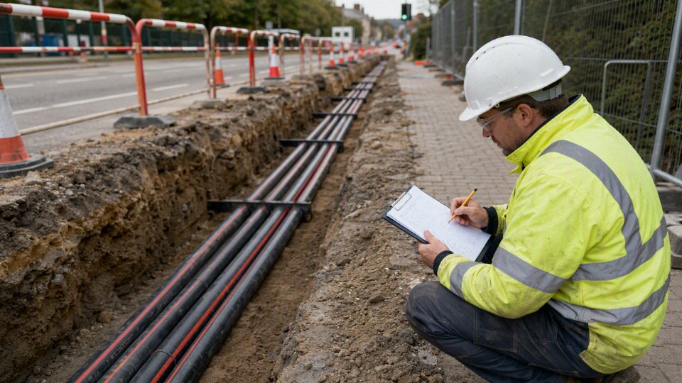
A qualified cable manufacturer reduces risk by challenging the specification before production starts. That means reviewing the service environment, matching conductor, insulation, screen, sheath, armor, and outer jacket to the duty, supporting compliance with the applicable standards, advising on compatible accessories, and coordinating production and delivery around the project schedule rather than treating the cable as a commodity reel.
Jinda supports international cable projects through integrated research and development, production, sales, technical support, and after-sales service. With multiple production bases, large manufacturing capacity, and supply experience across more than 50 countries, Jinda is positioned to support bulk procurement, specification review, and long-term project supply where cable performance and delivery timing both matter.
To move from a general underground cable discussion to a project-ready recommendation, share the voltage level, route length, installation method, expected load data, soil and environmental conditions, applicable standards, accessory requirements, and target delivery plan. Jinda can then help verify the cable specification and prepare a practical recommendation for quotation, procurement, and installation planning.