Choosing the wrong buried cable usually does not fail on day one; it fails after water ingress, insulation stress, soil movement, overload heat, or a backhoe nick has had time to work. Then the plant sees nuisance trips, feeder outages, production stops, emergency excavation, and cable replacement costs that dwarf the original material saving. The right direction is simple: match the cable construction to burial method, voltage, soil, load, and mechanical risk before anything goes in the trench.
Electrical cable can be buried only if it is rated for underground use, such as direct-burial cable, armored underground cable, or cable installed inside a suitable buried conduit or duct. The correct choice depends on voltage class, moisture exposure, soil thermal conditions, mechanical protection, local electrical code, and required service life.
The part that catches buyers out is that “underground” is not one specification. A 0.6/1 kV plant lighting feeder, a medium-voltage pump station supply, and a utility-style duct-bank run may all be buried, but they do not need the same sheath, armor, insulation system, cover depth, or ampacity review. That is where the engineering and the procurement decision have to meet.
Direct burial or conduit?
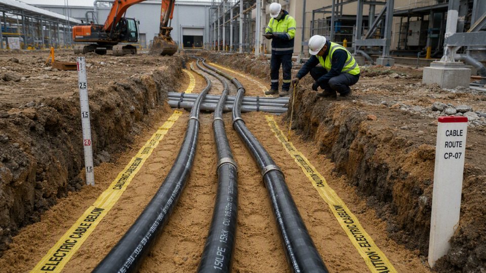
Direct burial is usually the faster, lower-civil-cost choice for long, open routes, but the cable must be built to live in soil for decades. Conduit or duct is the better choice where damage risk, paved surfaces, future replacement, or route control matter more than first cost. The mistake is assuming the raceway makes the cable “underground rated”; it does not.
In a direct-burial installation, the trench, bedding, cable construction, and backfill become one system. The cable sits in prepared sand, screened soil, or specified thermal backfill, then lives with ground moisture, seasonal temperature movement, compaction, stones that were missed by the crew, and whatever chemistry the site soil brings with it. That means the jacket, insulation system, armor if used, water blocking, sheath bonding arrangement, and markings all need to be suitable for direct contact with soil.
On a clean rural feeder or a solar farm collection route, direct burial can be hard to beat. You avoid buying and installing thousands of meters of duct, solvent-welding PVC in mud, pulling through long runs, and repairing crushed conduits after backfill. The trade-off is access. If a backhoe finds the cable five years later, or if the route must be modified after a new process building goes in, excavation is usually the repair plan.
Underground conduit or duct changes the failure modes; it does not eliminate them. PVC, HDPE, steel, concrete-encased duct banks, and other raceway systems reduce direct soil abrasion and give better route definition, especially under roads and yards where forklifts, reach stackers, cranes, and contractors are common. They also make future cable pulling possible if the layout was designed with enough spare ducts, sweep radius, pull boxes, and realistic pulling lengths.
The raceway introduces its own engineering limits:
- Pulling tension can damage conductors or terminations if the run is too long, too full, or poorly lubricated.
- Sidewall pressure at bends can deform insulation or jacket layers, especially on larger power cables.
- Water often accumulates inside underground ducts, so the cable still needs wet-location suitability.
- Heat dissipation is often worse in duct banks than in direct soil, particularly with dry sand, concrete encasement, congested ducts, or multiple loaded circuits.
- Maintenance is easier only if the duct is continuous, not collapsed, not packed with silt, and has accessible pulling points.
| Route condition | Direct burial usually fits when… | Conduit or duct usually fits when… |
|---|---|---|
| Long open ground | The route is stable, accessible, and unlikely to be excavated often | Future replacement or additional circuits are expected |
| Roads and paved areas | Only short protected crossings are needed | Traffic load, pavement removal cost, and damage risk are high |
| Industrial yards | The area has controlled excavation and low vehicle abuse | Forklifts, cranes, contractors, and changing layouts are common |
| Solar and wind sites | Many feeder runs cross open land with repetitive layouts | Collection points, road crossings, and inverter pads need protection |
| Aggressive soil | Cable design is proven for the soil chemistry and moisture | A raceway and selected backfill help isolate and manage the route |
A common hybrid is often the most practical arrangement: direct-burial cable in open trench, then sleeves or ducts at road crossings, building entries, slab penetrations, and high-risk yard sections. That works well only when both parts of the installation are respected. A cable that is rated for direct burial can generally pass through suitable sleeves if pulling limits and heat derating are checked, but a cable sold only for installation in conduit cannot automatically be dropped into open soil for the next 200 meters.
The ampacity side deserves attention because it is easy to underprice during procurement. Underground cable temperature depends on conductor load, insulation rating, spacing, burial depth, soil thermal resistivity, moisture, and nearby loaded circuits. Typical soil thermal resistivity used for review may fall around 0.9-2.5 K·m/W, but dry sand, poor backfill, and duct congestion can push the design toward derating. A cheaper civil design can become an expensive electrical design if it forces a larger conductor size or creates nuisance thermal limits in summer.
Before choosing one method, collect the decision inputs in writing:
- Local electrical code and the authority having jurisdiction
- Project voltage class, such as 0.6/1 kV low-voltage distribution or medium-voltage feeders up to common 26/35 kV systems
- Cable route drawings, including crossings, paved areas, drainage, and future building zones
- Expected maintenance strategy: excavate-and-repair or pull-and-replace
- Soil aggressiveness, groundwater, fill quality, and thermal assumptions
- Traffic load, compaction method, and burial depth
- Pulling distances, bend radius, duct fill, and pulling access
- Total installed cost, not just cable price or duct price
The boundary of this choice is the project environment. In a quiet greenfield corridor, direct burial may be the cleanest solution; in a congested plant with changing production lines and a maintenance crew that hates digging through reinforced concrete, conduit earns its cost quickly. The final decision should come from the installation code, cable datasheet, route risk, thermal calculation, and a contractor’s method statement, not from habit or the lowest material line item.
Cable types suitable for soil
The cable families that belong in soil are purpose-built underground power, control, instrumentation, communication, and utility distribution products with wet-location insulation, protective jackets, and verifiable markings. The risky part is not just voltage rating; soil adds moisture, chemical exposure, crushing, rodents, thermal derating, and fault-current behavior that ordinary indoor cable was never designed to survive.
Low-voltage direct-burial power cable
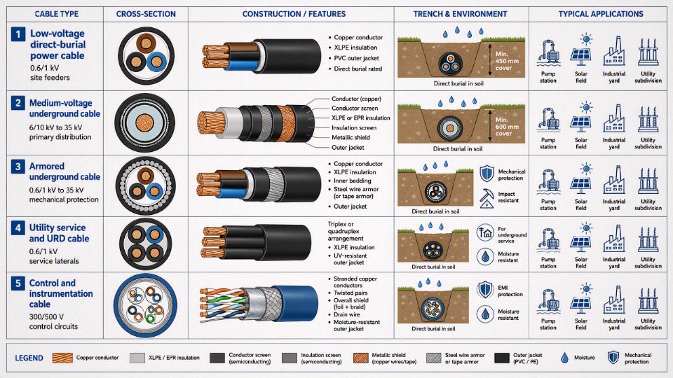
For 0.6/1 kV work, direct-burial low-voltage power cable is common in residential feeders, commercial site distribution, small industrial loads, utility service laterals, lighting circuits, pump stations, and outbuildings. Typical designs use moisture-resistant insulation such as XLPE, EPR, or other approved compounds, with an outer sheath selected for wet soil, abrasion during pulling, and long-term contact with backfill.
What matters on the plant floor is the combination of rating and installation method. A cable that behaves well on a tray in a dry electrical room may fail early underground because moisture migrates along conductor strands, collects at damaged jacket spots, and accelerates insulation deterioration under load cycling. If the route crosses a forklift yard, compacted gravel, or an area where maintenance crews keep “finding” buried services with a backhoe bucket, mechanical protection becomes just as important as insulation chemistry.
Medium-voltage underground cable
Medium-voltage underground systems usually use shielded XLPE or EPR insulated cable, commonly in classes from 3.6/6 kV up through 26/35 kV, depending on the network. These cables serve feeders, substations, industrial distribution, wind farms, solar plants, ports, mining sites, large campuses, and utility collection systems.
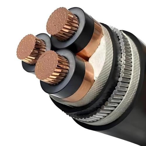
A proper MV underground cable is not just a thick low-voltage cable. It normally includes:
- A conductor screen to smooth the electric field at the conductor surface.
- An insulation screen to control stress at the insulation boundary.
- A metallic shield or screen for fault current return and touch-voltage control.
- A jacket suitable for wet underground service.
- Terminations, joints, and grounding arrangements tested for the cable system.
On MV cable, the accessories are part of the insulation system; a good cable with poor terminations is still a bad feeder. I have seen more MV trouble come from rushed jointing, shield bonding mistakes, and contaminated termination work than from the factory cable itself. Dust, humidity, nicked semicon layers, and an uncalibrated crimp tool can all show up later as partial discharge, heating, or nuisance trips.
Armored underground cable
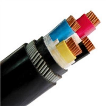
Armored cable earns its keep where the soil route is mechanically hostile: industrial yards, shallow sections, rodent-prone areas, road crossings, ports, refineries, process plants, and sites where future excavation is likely. Common armor forms include:
| Armor type | Where it is commonly used | Practical caution |
|---|---|---|
| Steel wire armor | Direct burial, industrial feeders, tensile loading during pulling | Heavy, magnetic losses may matter on single-core AC systems |
| Steel tape armor | General mechanical protection against impact and compression | Less flexible; check bending radius and corrosion protection |
| Aluminum wire armor | Single-core AC applications where magnetic armor is a problem | Lower mechanical strength than steel in some duties |
| Interlocked armor | Commercial and industrial wiring where code allows | Not automatically a direct-burial rating unless the cable is marked for it |
Armor improves crush and impact resistance, but it does not cancel the need for the correct sheath, bedding, corrosion protection, and bonding. The trade-off is weight, bending difficulty, termination time, and cost. In a clean, deep, well-marked route with controlled backfill, unarmored direct-burial cable in conduit or warning-taped trenching may be the better commercial choice.
Underground service and utility distribution cable
Utility distribution often uses recognized underground service configurations such as triplex, quadruplex, URD-style cable, and service lateral assemblies. These are not generic products; utilities and local standards usually define conductor material, neutral arrangement, insulation type, voltage class, identification, and accepted installation details.
Triplex and quadruplex arrangements are common for secondary distribution and service connections, while URD-style products are used in residential subdivisions, commercial developments, and utility networks. The buyer’s first check should be the serving utility specification, not a catalog photo. If the utility will not accept the construction, a technically decent cable can still become scrap from a procurement standpoint.
Control and instrumentation cable for underground systems
Buried control and instrumentation cable is used for pumps, gates, substations, tank farms, rail systems, conveyors, water treatment plants, and process automation. The cable may need:
- Wet-location insulation and sheath.
- Overall or pair shielding for signal integrity.
- Armor where excavation, rodents, or crush risk exists.
- Oil, chemical, or sunlight resistance at exposed transitions.
- Low-smoke or flame performance where it enters buildings or tunnels, if required by code.
Signal cables suffer differently from power cables. Water ingress may not trip a breaker; it may cause drifting analog readings, noisy level signals, intermittent valve feedback, or communication faults that maintenance chases for weeks. Separation from power cables, grounded shields, and route planning matter as much as the burial rating.
Solar, wind, and renewable-energy underground cable
Renewable sites mix several underground cable types: DC string cable, low-voltage AC cable, medium-voltage collector cable, grounding conductors, communication cable, and sometimes fiber. Solar cable may be exposed to UV above grade, then enter wet soil or conduit below grade; that transition is a common weak point if the product is rated for one environment but not the other.
Wind and solar collection systems also see thermal cycling, long feeder runs, harmonic content from power electronics, and grounding details that must match inverter or transformer requirements. Dry sand backfill, congested ducts, and high load factors can raise conductor temperature because the soil cannot carry heat away fast enough. Soil thermal resistivity used for ampacity review is often in the rough range of 0.9-2.5 K·m/W, but the correct value depends on local soil, moisture, compaction, and backfill.
Submersible pump and water-well cable
Submersible pump cable is designed for wet or submerged duty, including motor leads down wells, boreholes, reservoirs, and pumping systems. That does not automatically mean every length may be direct-buried across a yard. Check whether the product is rated for direct burial, whether the jacket resists soil chemicals and abrasion, and whether splices are approved for wet underground locations.
In practice, the splice is often the weak link. A pump cable with a neat factory jacket can be ruined by a taped field joint sitting in wet clay. Use listed wet-location splice kits and strain relief where the cable transitions from borehole to trench or control panel.
Mining, tunneling, and heavy industrial cable
Mining and tunneling cables may be extremely rugged, flexible, oil-resistant, abrasion-resistant, and flame-retardant. That still does not make every trailing cable suitable for fixed burial. Flexible trailing cable is built to move, drag, bend, and take abuse; fixed buried feeder cable is built to sit underground for years with controlled electrical stress, moisture protection, and stable thermal behavior.
The preferred choice flips with the duty. Use flexible mining or trailing cable for mobile machinery and temporary advancing faces. Use rated fixed underground feeder cable for permanent buried distribution unless the manufacturer specifically approves the flexible construction for that installation method.
Communication, fiber, and signal cable near power routes
Direct-burial fiber optic, data, coaxial, and signal cables are separate product families, not substitutes for power cable. They may include water-blocking yarns, corrugated armor, metallic shields, dielectric strength members, rodent protection, or tracer wires for locating.
When installed near power routes, plan:
- Separation distances required by local code and utility practice.
- Shield bonding and grounding for metallic communication cable.
- Crossings at right angles where practical.
- Identification tape and route markers.
- Surge protection where long outdoor runs enter equipment rooms.
The boundary is simple: communication cable can share a corridor with power only when separation, shielding, grounding, and access rules are engineered, not improvised in the trench.
Cables generally not to bury
Do not bury ordinary indoor cable just because it fits the conduit, looks heavy, or was left over from another job. The usual rejects include:
- Indoor non-metallic sheathed building cable not rated for underground use.
- Individual building wire installed without an approved raceway method.
- Appliance cord and portable extension cord.
- Non-wet-rated flexible cable.
- Temporary construction cable used as permanent wiring.
- Any cable with missing, damaged, painted-over, counterfeit, or unverifiable markings.
A cable's voltage rating alone does not prove it is suitable for direct burial.True
Underground suitability depends on wet-location rating, jacket construction, mechanical protection, chemical exposure, thermal conditions, installation method, and recognition by the applicable code or utility specification.
Construction features that matter
An underground cable survives because its construction controls five failure paths at once: electrical stress, heat, moisture, chemical attack, and mechanical abuse during installation and service. The right cable is not simply the thickest one; it is the design whose conductor, insulation, sheath, screens, armor, and bonding system match the soil, load, route, fault level, and termination hardware.
Conductor material and class
Copper gives lower resistance for the same cross-section, smaller terminations, and better tolerance for repeated thermal cycling at joints. Aluminum is lighter and usually cheaper per ampere on larger feeders, but it needs more cross-sectional area, careful termination preparation, compatible lugs, oxide control, and correct torque practice. I have seen more trouble from poor aluminum terminations than from the aluminum conductor itself.
The procurement choice often flips by project scale. On a short plant service run, copper may win because trenching, glands, lugs, and labor dominate the bill. On kilometers of medium-voltage feeder, aluminum can reduce cable cost and pulling load enough to matter, provided the engineering team accepts the larger diameter and termination discipline.
Conductor class also matters. Solid or compacted stranded conductors help with roundness and screen performance, while flexible stranded conductors suit tight equipment rooms and mobile or repeated-bending service. For buried fixed power circuits, flexibility is useful mainly at pulling and termination points; excessive flexibility is not a substitute for proper pulling radius and sidewall pressure control.
Insulation system
Underground insulation is selected for dielectric strength, thermal rating, moisture aging resistance, and how the cable will be terminated. Common options include:
| Insulation material | Where it is commonly used | Practical engineering notes |
|---|---|---|
| XLPE | Low-voltage and medium-voltage power cables | Good dielectric performance and thermal capability; widely used for 0.6/1 kV and MV systems when matched with proper screens and accessories. |
| EPR | MV feeders, industrial sites, flexible or wet-duty applications | More flexible than XLPE and often preferred where handling or moisture tolerance is a concern; usually larger and sometimes higher cost. |
| PVC compounds | Mainly low-voltage insulation or bedding in some cable designs | Economical and easy to process, but thermal and dielectric performance are more limited than XLPE or EPR for demanding power feeders. |
| Project-specific polymers | Chemical plants, rail, mining, offshore-style requirements | Selected for fire behavior, oil resistance, low smoke, low temperature, or special certification needs; supplier data and accessory compatibility must be checked. |
Insulation does not work alone. In medium-voltage cable, the conductor screen, insulation, and insulation screen form a controlled electrical stress system. If the screen is damaged, poorly stripped, contaminated with semicon residue, or mismatched to the termination kit, the failure can start as partial discharge long before the cable shows visible distress.
Water resistance
Water is the underground enemy that turns one nick in a jacket into a route-length problem. Good designs limit both radial ingress, where moisture penetrates inward through the sheath, and longitudinal migration, where water travels along conductor interstices, screen gaps, or armor beds after local damage.
Common water-control features include:
- Water-swellable tapes or powders around the conductor, screen, or core assembly, which expand when wet and block lengthwise migration.
- Filled conductors, where strand gaps are sealed to stop water traveling inside the conductor.
- Radial moisture barriers, such as metallic laminates or continuous metallic sheaths, used when wet soil, high water table, or long repair intervals justify the cost.
- Extruded sheath systems with PE, PVC, or specialty compounds selected to resist soil chemicals and handling damage.
- Blocked screen or armor bedding layers to keep a damaged area from becoming a long wet section.
Water blocking does not make a cable immune to bad installation. A sharp stone in the trench, a damaged drum flange, or a gland that lets rainwater sit at the termination can still defeat a well-built cable. The purpose is containment: keep a local wound local.
Outer sheath or jacket
The outer sheath takes the beating before the electrical system ever sees a problem. PVC is common, cost-effective, flame-retardant in many formulations, and reasonably easy to install. PE gives better moisture resistance and abrasion performance, but it generally has poorer flame behavior unless modified and needs attention at exposed transitions where sunlight and fire requirements apply.
LSZH compounds are chosen where smoke and halogen acid gas are unacceptable, such as tunnels, stations, confined industrial routes, or buildings where buried cable rises indoors. Chlorinated polyethylene and similar specialty jackets may be specified for oil, weathering, or chemical exposure. Low-temperature handling is a practical detail buyers miss: a jacket that performs well after installation can still crack if pulled from a cold yard without respecting the manufacturer’s minimum installation temperature.
Mechanical armor
Armor is selected when the route needs crush, impact, rodent, or pulling protection beyond the jacket. Steel wire armor is common for robust multicore cables and can tolerate demanding burial environments, but it increases diameter, weight, bending radius, and pulling load. Steel tape armor gives good circumferential protection but is less suited to tensile pulling duty. Aluminum armor is used where weight, corrosion behavior, or magnetic loss considerations favor it. Non-metallic armor or protective layers may be used where corrosion, single-core AC magnetic effects, or weight are concerns.
Armor brings obligations. Metallic armor may need bonding and grounding, and poor bonding can create touch-voltage or fault-clearing problems. Ferrous armor around single-core AC cables can create heating from circulating or induced currents if the phase arrangement and bonding are wrong. Corrosion protection also has to suit the soil; clay, industrial fill, fertilizer exposure, and stray DC currents all change the conversation.
A thicker or tougher underground cable is automatically the safest choice.False
Extra thickness may improve abrasion or impact resistance, but it can increase heat retention, bending radius, pulling tension, gland size, and termination difficulty. Reliability comes from matching the whole cable construction to the route, load, fault level, and accessories.
Electrical shielding, screens, grounding, and bonding
For low-voltage circuits, grounding may be handled by a separate protective conductor, armor, metallic sheath, or concentric neutral depending on the cable design and local code. For medium-voltage circuits, screens and shields are not optional decoration; they control the electric field and provide a defined path for charging current and earth-fault current.
Key elements include:
- Semiconductive conductor screens, which smooth the electric field at the conductor surface.
- Insulation screens, which create a controlled outer electrical boundary around the insulation.
- Copper tape shields or wire screens, which carry screen current and contribute to fault-current duty.
- Metallic sheaths, used where moisture barrier performance, fault duty, or mechanical robustness is required.
- Concentric neutrals, common in some utility-style designs, combining neutral and grounding functions when correctly sized and bonded.
Longer MV routes need a bonding study, not just a gland schedule. Solid bonding is simple and reliable for fault clearing, but it can create circulating currents and heating on long single-core runs. Single-point bonding reduces circulating losses but requires sheath voltage limiters and careful touch-voltage control. Cross-bonding is used on longer routes to balance induced voltages, but it needs accurate section lengths, link boxes, labeling, and maintenance discipline. If the plant maintenance team treats link boxes like ordinary junction boxes, the design benefit disappears quickly.
Thermal design
Ampacity underground is a heat-flow problem before it is a nameplate problem. Current heats the conductor; heat passes through insulation, screens, bedding, duct wall if present, backfill, and native soil. If any layer traps heat, conductor temperature rises, insulation aging accelerates, and the cable’s useful life shortens even when protection devices never trip.
The main variables are:
- Conductor size and material, which set electrical resistance and heat generation.
- Insulation temperature rating, such as the continuous operating limit stated by the manufacturer.
- Soil thermal resistivity, often reviewed in the rough range of 0.9-2.5 K·m/W, with dry sand, poor backfill, and congested duct banks pushing designs toward derating.
- Burial depth, which affects ambient ground temperature and heat dissipation path.
- Duct bank spacing and grouping, where multiple loaded circuits can heat each other.
- Load profile, because a steady 24/7 industrial load is less forgiving than an intermittent pump or standby feeder.
- Local ground temperature and seasonal moisture, which can change sharply between a wet spring and a dry late summer.
This is where oversizing becomes less simple than it looks. A larger conductor lowers resistance, but a heavier armored, multi-core, thick-sheathed cable in a tight duct bank may still run hotter than expected if spacing and soil data are poor. The conclusion stops holding when the installation environment changes: a cable that is acceptable in moist native soil may need derating, thermal backfill, larger conductors, or a different route in dry sand, concrete-encased ducts, or a congested plant corridor. The current equipment manual, cable data sheet, installation standard, and site thermal data need to agree before procurement freezes the design.
Standards, markings, and documentation
A cable is not acceptable for burial just because it looks heavy, black, armored, or “industrial.” Before purchase or installation, the buyer needs evidence that the exact cable construction, voltage class, test standard, and installation environment match the project requirements. For buried cable, the paperwork is part of the product; without it, approval, commissioning, insurance, and warranty can all become awkward very quickly.
The first check is the jacket marking. On a properly supplied cable, the outer sheath should normally show enough information to identify what has been delivered without guessing from the drum tag alone:
- Manufacturer name or registered identification
- Rated voltage, such as 0.6/1 kV or a medium-voltage class
- Conductor size and conductor material, usually copper or aluminum
- Core count and configuration
- Insulation and sheath material, such as XLPE, PVC, PE, LSZH, or project-specific compounds
- Applicable product standard or specification
- Wet rating, flame rating, UV rating, or direct-burial marking where the standard requires it
- Meter marking or sequential length marking, if supplied
- Batch, drum, order, or traceability code
That marking matters on the plant floor because cable often sits through civil delays, gets moved by forklift, and may be cut into sections before the electrical contractor is ready. If the drum tag is lost or rain-damaged, continuous jacket marking is what lets the site team confirm the cable before it disappears into a trench or duct bank.
Widely used standard families include IEC, BS, EN, UL, CSA, ICEA, AEIC, ASTM, and national utility specifications. None of these names should be treated as a universal pass. A low-voltage cable acceptable under one IEC-based project specification may still fail a local utility requirement for conductor identification, sheath color, fire performance, neutral sizing, concentric wires, water-blocking, or type-test evidence. In North America, listing and installation rules can drive a different approval route than an industrial export project using IEC cable. In utility work, the owner’s specification can be stricter than the national standard.
The correct standard depends on:
- Country and local electrical code
- Public utility, private industrial, mining, renewable, marine, or infrastructure use
- Voltage class and system earthing method
- Direct burial, conduit, duct bank, tray transition, or mixed installation
- Fire-performance requirement inside buildings or tunnels
- Soil moisture, chemical exposure, termite or rodent risk
- Client-approved vendor list and inspection regime
There is a trade-off here. Standard catalog cable is usually faster and cheaper to buy, with fewer document reviews. Project-specific cable can solve approval issues and harsh service conditions, but it adds lead time, minimum order quantities, and more chances for drawing revisions to stall production. The preferred choice flips when the cable route crosses regulated zones, utility interfaces, tunnels, substations, or export jurisdictions where acceptance documents matter as much as copper and insulation.
For procurement, request the document set before issuing the final purchase order, not after the drums are already in the yard. A practical buried-cable package should include:
- Technical datasheet with construction, dimensions, electrical ratings, bending radius, temperature limits, and installation guidance.
- Product standard declaration identifying the standard and edition used.
- Type test reports, where required by the project or standard.
- Routine test records for the supplied batch, commonly covering conductor resistance, voltage test, insulation checks, and dimensional verification as applicable.
- Material data where needed, especially for sheath compound, flame performance, halogen content, oil resistance, UV resistance, or water-blocking materials.
- Factory inspection and test plan for projects with hold points or witnessed tests.
- Packing list and drum schedule showing drum numbers, lengths, weights, and cable references.
- Certificate of conformity matched to the purchase order and batch.
- Warranty terms, including conditions that could void coverage, such as incorrect storage, pulling damage, or operation above rated temperature.
On delivery, do not rely only on the certificate. Inspect the cable physically before signing it through goods receipt:
- Drum flanges intact, no crushed lagging, broken bolts, or signs of a dropped reel
- Cable ends sealed against moisture ingress
- Jacket marking continuous and matching the order
- No sheath cuts, flat spots, abrasions, swelling, or exposed armor
- Drum number and batch traceable to the test certificate
- Storage condition suitable for the sheath material and site climate
- Cable length checked against drum schedule and, where needed, meter marking
- Correct rotation direction observed before pulling from the drum
International projects need another layer of control. Export packaging, English-language certificates, customs documents, project drawings, third-party inspection reports, and evidence of compliance with the client-approved vendor list may all be required before shipment release. This is where early document review saves money; correcting a certificate format is easy before dispatch and painful once the cable is sitting at a port under demurrage.
Shandong Jinda Special Cable Group’s integrated manufacturing, technical support, and export experience are relevant for this part of the job because standard alignment, testing records, drum scheduling, and shipment documentation have to move together. For bulk procurement or long-term supply programs, that coordination helps the buyer keep cable design, approval documents, factory inspection, and export paperwork tied to the same traceable production order.
Site conditions that change selection
A burial-rated cable is only the starting point; the trench decides the final construction. Water, soil chemistry, vehicle loading, thermal resistance, rodents, fault duty, and route geometry can push the design toward water-blocked conductors, heavier sheaths, armor, conduit, deeper cover, or lower ampacity than the catalog table suggests.
Moisture, water table, and drainage
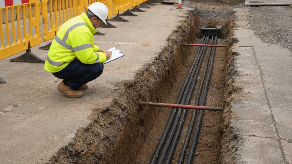
Wet ground is not just “more damp.” Saturated soil, seasonal flooding, and standing water inside ducts change the failure mode from slow jacket aging to water migration along the cable, joint, or conductor interstices. In low-lying industrial parks I have seen ducts behave like drains; once one handhole fills, the water level can sit against terminations for months.
Review these conditions before approving the cable construction:
- High water table or flood-prone route: consider radial water protection, such as a metallic moisture barrier or suitable water-resistant sheath system, depending on voltage and cable design.
- Long duct runs with poor fall: assume water may stand in the duct unless the civil design proves otherwise.
- Medium-voltage feeders with joints: assess longitudinal water blocking so damage at one point does not allow water to travel far along the conductor or screen.
- Clay soils and low drainage backfill: expect slower drying after rain and more persistent sheath exposure.
- Seasonal monsoon or rainy trenching: jointing discipline becomes as important as cable selection; wet insulation screens and dirty joint bays are a common source of early failures.
The trade-off is cost and handling. Water-blocked and barrier constructions can be stiffer, heavier, and less forgiving during pulling, but skipping them in a wet route can turn one sheath nick into a long-term reliability problem.
Chemical and corrosion exposure
Soil chemistry decides whether a standard outer sheath and armor system will last. Acidic or alkaline soils, salts, fertilizer runoff, hydrocarbons, sewage zones, and coastal chloride exposure all attack different parts of the cable. A galvanized steel armor that looks conservative on paper may be the wrong choice in a corrosive coastal trench unless the sheath and corrosion protection are selected for that environment.
Check for:
- Low or high pH soil: can accelerate jacket or metallic component degradation, depending on material.
- Salts and coastal aerosols: raise corrosion risk for armor, screens, glands, and exposed earthing hardware.
- Hydrocarbons and solvents: common near fuel farms, workshops, refineries, and generator yards; verify jacket compatibility rather than assuming PVC or PE is acceptable.
- Fertilizers and agricultural chemicals: relevant for irrigation pumps, farms, greenhouses, and rural feeders.
- Sewage or wastewater zones: combine chemical attack with biological activity and persistent moisture.
For procurement, ask for the sheath compound, armor material, corrosion protection method, and any chemical resistance data the manufacturer can actually document. Do not accept “suitable for underground” as a substitute for route-specific exposure review.
Mechanical loading and physical damage
Mechanical risk is where many buried cable decisions become civil-engineering decisions. Road crossings, forklifts, mobile cranes, compactors, rock backfill, settlement, and future excavation can damage a cable that would survive perfectly in clean sand under a landscaped strip.
Typical protections include:
- Armor for crush, impact, and digging resistance, subject to bending and termination requirements.
- Protective conduit or ducts at road crossings, plant entrances, and future expansion zones.
- Concrete slabs or tiles above the cable where excavation risk is high.
- Warning tape and route markers placed at the correct depth, not tossed into the trench as an afterthought.
- Selected bedding and screened backfill to prevent sharp stone contact with the sheath.
There is a practical flip point: armor improves damage tolerance, but conduit can be better where replacement access matters or where civil loading is concentrated. In a plant with frequent modifications, a duct bank with spare ways may cost more at installation and save weeks later.
Thermal environment and ampacity loss
Underground ampacity is controlled by how easily heat leaves the conductor, passes through insulation and sheath layers, crosses the bedding, and dissipates into surrounding soil. Soil thermal resistivity used for review often falls around 0.9-2.5 K·m/W, but dry sand, poorly compacted backfill, congested ducts, and heat from nearby steam or power lines can push the design toward derating.
Review these items together, not one at a time:
- Grouped circuits and duct banks: mutual heating can reduce allowable current sharply.
- High-load industrial operation: continuous loading is harder on cable than short residential peaks.
- Emergency overload philosophy: a cable sized only for normal current may not tolerate repeated contingency loading.
- Neighboring utilities: steam lines, hot process drains, and other power feeders raise ambient trench temperature.
- Backfill selection: thermal sand or controlled backfill may be justified for large feeders, but it must be installed consistently along the route.
The same cable can be reliable in one trench and fail early in another if backfill, drainage, derating, joint quality, or fault protection changes. This is why ampacity should be checked against the installed arrangement, not copied from a free-air or single-circuit catalog value.
Biological attack, voltage duty, and route layout
Rodents, termites, and insects are not universal problems, but where they exist they are persistent. Rural pump stations, grain facilities, tropical sites, cable routes near food waste, and older utility corridors may justify armor, tougher outer sheaths, chemical-resistant jackets, or protective conduit. The preferred choice depends on local pest behavior; a specification copied from a temperate urban site may be weak in a warm, wet region.
Voltage level and fault duty also change the cable design. Low-voltage systems around 0.6/1 kV have different insulation, screening, and earthing needs from medium-voltage feeders such as 3.6/6 kV to 26/35 kV. For MV cable, insulation screens, metallic shields, armor bonding, earth fault current paths, and protection settings must be coordinated. A shield or armor that cannot carry fault current until protection clears is a safety and reliability defect, not a minor accessory issue.
Route geometry deserves an early drawing review:
- Minimum bend radius: check against the current cable datasheet, especially for armored or water-barrier designs.
- Pulling length and sidewall pressure: long runs with several bends may need larger ducts, more pull points, or a different route.
- Elevation changes: water collection and pulling tension both change on sloped routes.
- Joint bay access: leave room for clean jointing, testing, and future repair.
- Crossings with gas, water, steam, and communication lines: maintain required separation under local code and utility rules.
- Termination locations: avoid forcing stiff cable into tight panels or outdoor boxes with poor gland access.
Climate and installation season
Installation season can damage a good cable before it is energized. Low temperatures make many jackets less flexible and more vulnerable to cracking during unreeling or bending; hot weather can soften jackets and raise drum-storage concerns, especially under direct sun. Freeze-thaw movement can disturb shallow routes, while rainy-season trenching increases the chance of contaminated bedding, floating ducts, and rushed jointing.
This section’s guidance stops being enough when the route has high voltage, high fault levels, unstable soil, unusual chemicals, or critical continuous operation. At that point, the buyer should require a route survey, soil data, thermal calculation, short-circuit review, and installation method statement before releasing the cable order.
Installation practices for buried cable
A good underground cable can be ruined before it ever carries load. Treat installation as part of the cable system, not as civil work with an electrical item dropped into the trench.
Pre-installation review
Before the drum is moved from storage, the site team should verify:
- Approved drawings and cable schedule: route, voltage class, conductor size, core count, armor or sheath type, and destination tags.
- Drum numbers and traceability: match drum labels to purchase documents, test certificates, and installation sections.
- Route survey: check existing utilities, road crossings, drainage paths, chemical exposure areas, future excavation zones, and access for drum stands or pulling equipment.
- Trench depth and cover: confirm the required cover against the local electrical code, project specification, voltage, and mechanical protection method.
- Bend radius: check both the cable manufacturer’s minimum radius and the actual trench geometry at corners, risers, joint bays, and duct entries.
- Pulling plan: calculate expected pulling tension and sidewall pressure, especially for long duct runs or multiple bends.
- Separation requirements: maintain clearance from other power cables, communication circuits, gas, water, process piping, and earthing conductors as specified.
- Authority approvals and permits: do not assume the route is released because the cable has arrived. I have seen more cable damage caused by rushed re-routing than by bad cable.
Trench preparation
The trench bottom should be stable, clean, and shaped before cable laying starts. Remove sharp stones, scrap steel, broken concrete, welding rods, and dried construction debris. Use suitable bedding material, often sand or screened soil, where the project specification requires it.
Drainage matters. A trench that fills with muddy water during installation can contaminate bedding, float lightweight ducts, and make joint bay work almost impossible to control. If the soil wall is unstable, shore or slope the trench rather than letting collapsed material fall onto the cable. The trade-off is time and civil cost, but the alternative is hidden point loading on the sheath or armor.
Cable handling during payout and pulling
Control the drum rolling direction, lifting method, and payout direction. Drums should be lifted with proper shafts or spreader arrangements, not hooked through flange gaps with whatever chain is nearby. During payout, avoid reverse bending, twisting, dragging across trench edges, and jacket abrasion from rollers with damaged bearings.
Pulling tension and sidewall pressure are not paperwork details. High tension stretches conductors and insulation systems; high sidewall pressure at bends can flatten or bruise the cable, especially in duct entries and sweeping bends. Lubricant, intermediate pulling points, larger bend radius, or changing from pulling to laying-in can solve the same route problem with less cable stress. The preferred method flips when access is poor: a duct pull may protect the cable mechanically, but a congested duct with tight bends can be harder on the cable than an open-trench lay.
Protection in the trench
Typical protection measures include:
- Sand bedding below and above the cable where specified.
- Selected backfill free of sharp stones and construction waste.
- Warning tape at the specified level above the cable.
- Marker boards, protective tiles, concrete covers, or mechanical protection slabs in traffic or excavation-prone areas.
- Conduits or sleeves at road crossings, wall penetrations, and areas with future civil work.
- Route markers at direction changes, joint locations, road crossings, and entry points.
Do not use protective material as an excuse to ignore depth. Cover depth, mechanical protection, and route marking work together; one does not fully replace the others unless the authority or project specification says so.
Jointing and terminations
Jointing should be done by trained installers using the correct kit for the cable construction, voltage class, conductor material, screen, armor, and sheath. Cleanliness is not cosmetic here. Moisture, dust, strand particles, or a nick in semiconductive screen removal can become a weak point.
For medium-voltage cables, stress control, screen continuity, insulation preparation, and sheath sealing are critical. Terminations also need correct lug selection, crimping or shear-bolt procedure, torque control, creepage distance, and phase identification. A common procurement mistake is buying cable and accessories separately without checking dimensional compatibility.
Testing before energization
Testing should be defined in the project specification and matched to cable type and voltage class. Common checks include:
- Continuity.
- Conductor resistance.
- Phase identification.
- Insulation resistance.
- Sheath or jacket integrity testing where applicable.
- VLF or other approved high-voltage tests for certain medium-voltage systems.
- Partial discharge testing on selected medium-voltage systems, depending on project requirements and available test access.
Do not rely on insulation resistance alone to prove that a buried cable jacket survived installation. A scraped outer sheath may still show acceptable insulation readings on day one, then admit moisture and create corrosion, screen damage, or tracking months later.
A buried cable can pass an insulation resistance test even if its outer jacket was damaged during pulling.True
Insulation resistance mainly indicates the condition between conductors and earth or between conductors. Localized outer sheath damage may not immediately create a conductive path, but it can allow delayed water ingress and corrosion.
Backfilling and records
Backfill in layers and compact carefully, without dropping large stones or running compactors directly over shallow, unprotected cable. Record the as-built route, actual depth, joint and termination locations, crossing details, cable drum numbers, test values, and any route deviations. Those records are not clerical leftovers; they are what maintenance will use ten years later when a feeder trips in the rain and nobody remembers where the joint bay was moved.
Failures and inspections below grade
Most buried cable failures are not mysterious “old cable” problems; they come from moisture, mechanical abuse, heat, corrosion, accessories, or fault stress acting for months before the trip happens. The useful maintenance question is not only where the cable failed, but what visible signal, test trend, or route condition could have warned you earlier.
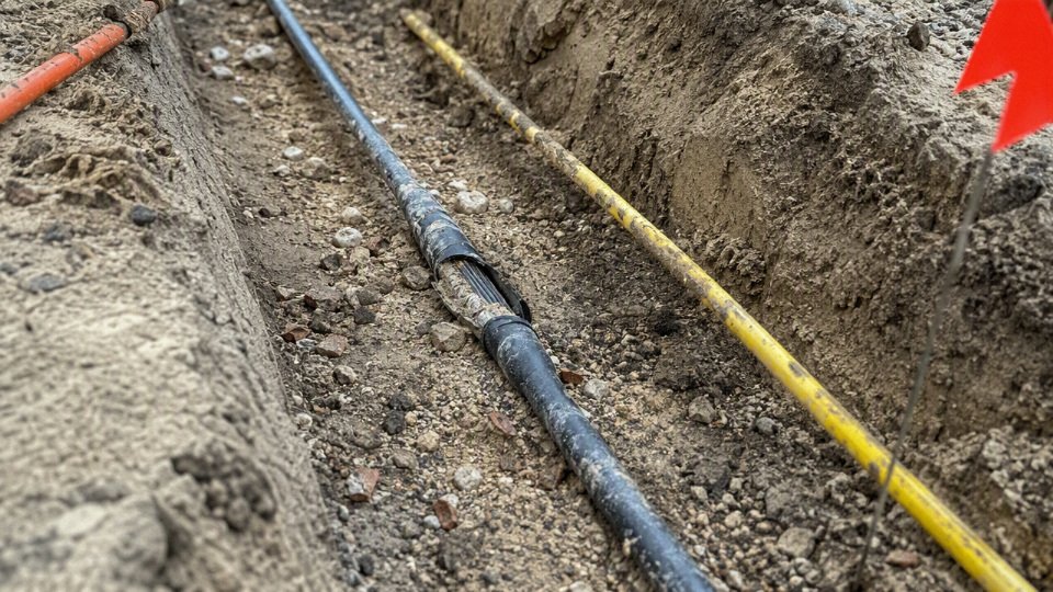
The common failure mechanisms below grade usually fall into a few repeatable groups:
- Moisture ingress: Small jacket cuts, poorly sealed ends, cracked gland entries, failed joints, and water-filled ducts allow moisture to migrate along screens, armor bedding, conductor strands, or filler spaces. Once water reaches vulnerable insulation or metallic components, it can drive corrosion, tracking, water-treeing in susceptible insulation systems, and eventual breakdown. In practice, I get suspicious when a duct always drains dirty water after rain or when stored cable ends were left open on a yard reel.
- Mechanical damage: Crushing from poor backfill, cuts from sharp stones, abrasion at duct mouths, excessive pulling tension, shallow cover, third-party excavation, rock pressure, and repeated ground movement all leave defects that may survive commissioning but fail later under load or surge. A nicked outer sheath is not cosmetic underground; it is the start of a wet, stressed, hidden failure point.
- Thermal aging: Sustained overload, high soil thermal resistivity, grouped circuits, blocked ducts, and undersized conductors raise conductor temperature. Heat accelerates insulation aging because chemical degradation rates increase with temperature; the owner may see no alarm until insulation margin is already consumed. Larger conductors, spacing, or thermal backfill cost more upfront, but the trade is lower operating temperature and better service life. That advantage weakens if load growth assumptions are wrong or the route later becomes thermally crowded.
- Chemical and corrosion damage: Contaminated soil, aggressive backfill, industrial drainage, fertilizers, hydrocarbons, and stray current conditions can embrittle sheaths, corrode armor, attack metallic screens, and consume concentric neutrals. This is especially painful because the electrical cable may still test acceptably while its protection system is already disappearing.
- Accessory failure: Joints, terminations, stress cones, screen connections, lugs, and moisture seals often fail before the cable body. The usual causes are poor workmanship, incompatible kits, wrong crimp tooling, poor surface preparation, incorrect screen cutback, or moisture trapped during installation.
- Electrical stress and fault events: Overvoltage, lightning, switching surges, poor grounding, overheated screens, harmonic loading, and repeated fault current exposure can weaken insulation and accessories. One severe fault may not destroy a feeder immediately, but it can leave carbonized paths, damaged shields, or partially degraded joints.
Inspection should combine visual route discipline with electrical trending:
- Patrol routes for excavation activity, settlement, exposed warning tape, damaged markers, washouts, and standing water over duct banks.
- Check accessible terminations, joint bays, link boxes, and panels for hot spots, discoloration, sheath bonding issues, loose lugs, and water entry.
- Trend insulation resistance, sheath test results, and grounding current rather than treating each test as a one-off pass or fail.
- Use partial discharge assessment where voltage class and cable construction make it appropriate, especially after jointing work or unexplained trips.
- Apply fault location and time-domain reflectometry to narrow suspected damage zones before opening the ground.
- Excavate at credible damage points instead of repeatedly re-energizing a feeder that has already shown abnormal test behavior.
Buying the cheapest cable body cannot compensate for poor route protection, low-quality accessories, insufficient testing, or missing as-built records. A well-built buried system is cable, joints, installation records, route control, and maintenance access treated as one asset, not separate purchase orders.
Frequently asked questions
Can any electrical cable be buried if it is inside conduit?
No. Conduit improves mechanical protection and makes replacement easier in some layouts, but the cable inside still has to be suitable for the environment created inside that conduit. Underground conduit commonly fills with condensation or groundwater, so the cable usually needs a wet-location rating and the correct voltage, insulation, and jacket system for the installation.
What marking should I look for on a direct-burial cable?
Look for a clear manufacturer marking and documentation stating direct burial, underground use, or the applicable cable type and standard that permits burial. The exact wording depends on the market and standard system, so do not buy from jacket printing alone. Ask for the datasheet, test certificate, voltage rating, conductor material, insulation type, sheath material, and installation conditions covered by the design.
Is armored cable always required underground?
No. Armoring is required when the installation needs extra mechanical protection against digging damage, stones, settlement, rodents, or industrial traffic, but it is not automatically required for every buried circuit. In clean sand bedding inside a protected route, an unarmored direct-burial cable may be acceptable; in a yard with forklifts, scrap handling, or poor excavation control, armor often earns its cost.
Can outdoor cable be buried directly in soil?
Not unless it is also rated for direct burial. “Outdoor” may only mean sunlight, rain, and temperature exposure above ground. Soil adds sustained moisture, pressure, chemical exposure, abrasion during pulling or backfilling, and heat dissipation limits.
Any outdoor-rated electrical cable can be buried directly if the trench is deep enough.False
Outdoor rating and direct-burial suitability are not the same. The cable must be documented for underground or direct-burial service, and burial depth does not compensate for an unsuitable insulation or jacket system.
Is copper better than aluminum for buried cable?
Copper gives higher conductivity in a smaller cross-section, better tolerance of termination abuse, and is often preferred for compact routes or critical loads. Aluminum is widely used for larger feeders because it can reduce material cost and weight, but it needs proper lug selection, oxide control, torque discipline, and allowance for larger conductor size. The better choice depends on ampacity, voltage drop, joint quality, theft risk, and installed cost, not conductor metal alone.
How deep should electrical cable be buried?
Typical direct-burial cover for many low-voltage installations is roughly 450-760 mm, but the required depth depends on local electrical code, voltage, route use, mechanical protection, warning tape, conduit, and surface loading. A cable crossing a road, plant entrance, or future excavation zone may need more protection than the same cable under a landscaped strip.
Does underground cable need to be waterproof?
It needs to be designed for wet underground service, but “waterproof” is too loose a word. Many underground failures come from water migration through damaged jackets, poor joints, or cable ends left open during storage. For critical feeders, water-blocking tapes, sealed conductor designs, proper glands, and tested joints matter as much as the cable jacket.
Can medium-voltage cable be direct buried?
Yes, medium-voltage cable can be direct buried when the cable construction, shielding, jacket, fault rating, bedding, separation, earthing, and installation method are engineered for it. Common underground MV systems include classes from 3.6/6 kV up to 26/35 kV, with higher systems handled project by project. MV direct burial should never be treated like a heavier version of low-voltage work; terminations, sheath bonding, and testing become much less forgiving.
What is the difference between wet-rated and direct-burial cable?
Wet-rated cable is suitable for moisture exposure, such as inside underground conduit that may collect water. Direct-burial cable is built and approved for direct contact with soil, including moisture, pressure, and installation abrasion. A cable can be wet-rated without being direct-burial rated, so check both requirements.
Should buried cable be tested before energization?
Yes. At minimum, the contractor should perform the tests required by the applicable standard, project specification, and cable manufacturer’s instructions. Depending on voltage and cable type, that may include continuity, insulation resistance, sheath integrity, phasing, VLF testing, partial discharge assessment, or other acceptance tests. Testing is cheaper before the trench is fully forgotten and the production line is waiting on power.
How long does buried electrical cable last?
A correctly selected and installed underground cable commonly targets about 25-40 years of service, but that range depends heavily on soil conditions, loading, installation damage, joint workmanship, moisture control, and thermal environment. Dry sandy backfill, congested ducts, and high load factor can raise conductor temperature and shorten insulation life if ampacity was estimated too optimistically.
What information should I send to a cable manufacturer for quotation?
Send enough detail for the manufacturer to check both electrical duty and burial suitability:
- Voltage class and system earthing method
- AC or DC service, load current, duty cycle, and allowable voltage drop
- Conductor preference: copper, aluminum, or open to recommendation
- Installation method: direct buried, duct, tray-to-trench transition, or mixed route
- Burial depth, soil type, backfill plan, groundwater, and expected soil thermal resistivity if known
- Route length, number of parallel circuits, spacing, and nearby heat sources
- Required standards, approvals, fire performance, sheath color, and marking language
- Armoring, water-blocking, rodent resistance, or chemical resistance requirements
- Drum length limits, delivery schedule, destination port or site, and inspection documents needed
Verify your burial cable specification
Use this checklist before you issue an RFQ, approve a submittal, or let a contractor substitute “equivalent” cable. The buried cable that belongs in the ground is not the one that simply looks rugged; it is the cable whose rating, construction, installation method, and documentation match the actual underground environment and duty cycle.
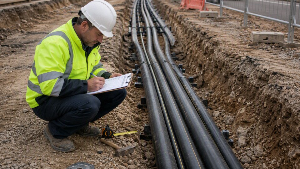
- Confirm the installation method first
- Direct burial in prepared trench bedding.
- Underground conduit with cable pulled after civil works.
- Concrete-encased duct bank.
- Sleeve crossings under roads, slabs, rail tracks, or plant entrances.
- Mixed installation, such as buried cable rising into tray, passing through conduit at crossings, then returning to soil.
Mixed routes cause the most missed details. A cable may be acceptable in soil but need different pulling limits, jacket protection, fire behavior, or UV resistance where it emerges near equipment.
- Verify the electrical requirements
- Voltage class, such as 0.6/1 kV, medium-voltage feeder ratings, or project-specific higher voltage.
- Conductor size and material: copper or aluminum.
- Number of cores and grounding arrangement.
- Continuous load profile, cyclic loading, starting currents, and seasonal demand.
- Short-circuit rating and fault-clearing time.
- Future capacity margin.
Ampacity is not just a catalog number. Soil thermal resistivity, grouping, duct fill, backfill quality, and load factor can move the safe current rating enough to change conductor size.
Verify the environmental requirements
- Soil moisture and drainage.
- Chemical exposure from hydrocarbons, fertilizers, salts, acids, alkalis, or industrial runoff.
- Water table level and flood risk.
- Ambient and soil temperature.
- Rodent or termite exposure.
- Vehicle loading, compaction, vibration, and route depth.
- Access for later maintenance or fault repair.
In practice, a short crossing under a forklift route can be harder on cable than a long quiet run through landscaped soil.
Verify the construction requirements
- Insulation material and temperature rating.
- Outer sheath material and thickness.
- Armor type, if mechanical protection is needed.
- Metallic screen or shielding for medium-voltage systems.
- Longitudinal or radial water blocking, where required.
- Fire performance for exposed sections, tunnels, basements, or building entries.
- UV resistance where the cable is exposed at risers or terminations.
- Compatibility with joints, glands, lugs, terminations, and pulling equipment.
- Verify the compliance and procurement package
- Applicable project, national, or international standards.
- Required cable markings.
- Routine test reports, type test references, certificates, and inspection documents.
- Drum length, packing method, lifting points, and storage instructions.
- Delivery schedule, batch traceability, and project documentation format.
For a technical review or project quotation, share the route length, voltage class, installation method, soil conditions, required standards, conductor preference, approximate load, and purchase quantity with Jinda. Jinda’s engineering and sales teams can help verify the underground cable specification against the application and prepare a quotation for the required cable package.