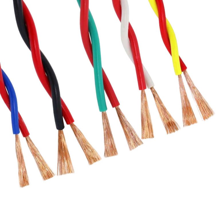
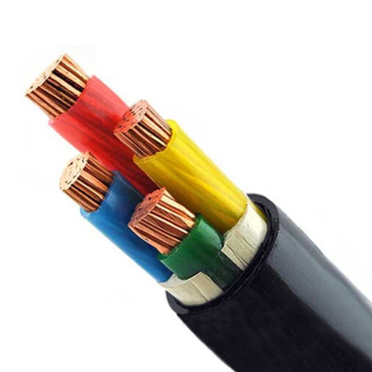
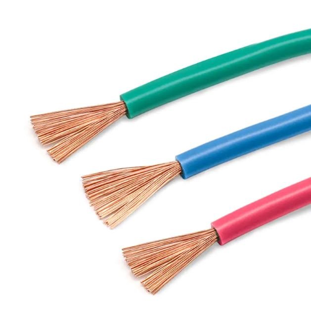
A buried cable usually fails where nobody can see the damage starting: wet soil, nicked jacket, poor backfill, overloaded conductor, or a joint that was “good enough” on installation day. The operational result is nuisance tripping, voltage drop, feeder outage, or a shutdown that needs excavation before anyone can even diagnose it. The cost is rarely just the cable; it is trenching, downtime, permits, labor, and lost production, so service life has to be engineered before the cable goes underground.
A well specified and correctly installed direct burial cable commonly targets 25 to 40 years of service. Premium industrial and medium voltage systems may reach 40 to 60 years when soil conditions, burial depth, mechanical protection, conductor loading, moisture sealing, and installation workmanship are properly controlled.
The useful question is not just “how many years?” but “what will shorten that life in this site?” A cable buried 600 mm under a dry landscaped area does not age like a feeder under a hot paved yard with truck traffic, standing water, and a maintenance crew that backfills with whatever came out of the trench.

Lifespan ranges by cable type
A defensible service-life expectation depends more on the cable construction and installation environment than on the label “direct burial.” Good low voltage direct burial cable often aims for several decades, while premium industrial and medium voltage systems can justify longer design expectations when thermal loading, soil chemistry, water control, and termination workmanship are managed. The category sets the starting point; the site conditions decide whether it holds.
All direct burial cables in the same voltage class should be expected to last the same number of years.False
Voltage class is only one factor. Insulation material, jacket compound, shielding system, metallic armor or screen design, water blocking, burial depth, soil chemistry, thermal loading, and installation damage can produce very different service lives within the same voltage category.
| Cable category | Reasonable expectation when correctly specified and installed | What usually limits life |
|---|---|---|
| Residential and light commercial low voltage feeders | Commonly several decades; often aligned with the 25 to 40 year planning range | Jacket cuts, shallow burial damage, water ingress, overloaded circuits, poor splices |
| Agricultural and light industrial low voltage cable | Similar planning range, but more site-dependent | Fertilizer, manure, irrigation water, rodents, machinery damage, seasonal wet/dry cycling |
| Industrial low voltage feeders with XLPE or similar thermoset insulation | Often selected for more stable long-term service; premium systems may support longer asset planning | Sustained heat, chemical soil attack, poor bedding, jacket defects, unverified accessories |
| Medium voltage direct burial cable | Can be planned for long service, commonly toward the higher end when the whole system is controlled | Partial discharge, screen corrosion, water treeing, termination stress, jacket failure |
| Control, instrumentation, and signal cable | Load is low, but life can still be cut short by environment | Moisture in shields, corrosion, EMI problems, crushed pairs, jacket cracking |
| Fiber optic and communication cable | Not governed by conductor heating; durability depends on mechanical and moisture design | Crush, rodents, water migration, bend abuse, jacket degradation |
For common low voltage power feeders used around homes, small commercial buildings, irrigation pumps, outbuildings, and light industrial loads, I would not buy on conductor size alone. The cable needs insulation and jacket materials rated for direct burial, enough mechanical toughness for the trench conditions, and a temperature rating suitable for the circuit design, commonly 70, 90, or 105 degrees Celsius depending on construction. A cable that lives comfortably below its thermal envelope ages slowly; the same cable run hot every afternoon under a compacted driveway can harden, crack, or lose insulation resistance much earlier.
Industrial low voltage feeders are a different purchase. Buyers usually look for XLPE or similar thermoset insulation, thicker or more robust jackets, documented routine testing, and construction details that tolerate pulling, bedding irregularities, and damp soil. The trade-off is cost and handling: heavier jackets, armor, and larger bending radii make installation slower, and a rushed crew can damage a better cable before it ever sees load. A higher-grade feeder only earns its longer service expectation if the trench, pulling tension, bending radius, jointing, and backfill are controlled as part of the job.
Medium voltage direct burial cable is less forgiving. Conductor shielding and insulation shielding are there to smooth the electric field; metallic screens or concentric neutrals provide a return path and help control fault behavior; the outer jacket protects the screen system from moisture and soil. If the screen corrodes, the jacket is punctured, or the termination is built with poor stress control, the failure mechanism is not simple “wear.” Local electrical stress can drive partial discharge, tracking, insulation erosion, or water treeing depending on construction and conditions. That is why medium voltage life is judged as a system: cable, joints, terminations, grounding, testing, and installation workmanship.
Control, instrumentation, and signal cables deserve separate treatment because their conductors may carry very little current. Heat is often not the life-limiting factor. Moisture wicking along a shield, corrosion under a foil or braid, electromagnetic interference from nearby power feeders, and jacket nicks from trench stones can make the cable electrically unreliable long before the copper conductor is physically worn out. In a plant, that may show up as nuisance trips, drifting analog signals, intermittent valve feedback, or communication faults that disappear when the trench dries out. Those are ugly faults to chase at 2 a.m.
Direct burial fiber optic and communication cables are another class again. There is no conductor temperature aging in the normal power-cable sense, so buyers should focus on water blocking, crush resistance, tensile strength, rodent protection, and jacket material. Loose-tube, armored, dielectric, gel-filled, dry water-blocked, and rodent-resistant designs each have their place. The right choice depends on pulling method, soil, traffic loading, lightning exposure, and whether future fault location and repair access are practical.
One mistake still turns up on retrofit jobs: ordinary indoor cable placed underground “just for a short run.” Non-rated cable may absorb water, crack under soil pressure, corrode at shields or conductors, and fail insulation resistance tests far earlier than expected. Conduit does not automatically fix that if the conduit fills with water, which many underground conduits eventually do. Verify the cable marking, current manual, and local electrical code rather than relying on appearance.
Heavy armor is useful against impact, rodents, and rough handling, but it is not a magic life extender. In chemically aggressive soil, damaged outer jackets can let moisture reach steel wire, tape armor, screens, or other metallic layers, creating corrosion paths. Armor can also make the cable harder to bend and seal correctly at glands and terminations. The preferred choice flips when mechanical risk is greater than corrosion risk, or when the project can specify corrosion-resistant materials and proper oversheath protection. If soil data is unknown, especially near industrial fill, coastal ground, farms, or old process areas, assume the lifespan estimate is provisional until the soil and installation method are checked.
Aging mechanisms underground
Buried cable usually ages from a combination of moisture, heat, electrical stress, chemical exposure, corrosion, and mechanical damage, not from one simple “years in the ground” clock. The difficult part is that the worst mechanisms are often hidden until insulation resistance drops, a shield corrodes away, or a joint fails under load on the wettest night of the season.
Moisture ingress is not only a jacket problem
Water gets into buried cable systems through more paths than many purchase specifications admit. A tough outer jacket helps, but it is not a magic pipe coating. In practice, moisture entry often starts at the weak points:
- Jacket cuts from pulling over trench stones, conduit edges, rebar, or a loader bucket.
- Failed joints where heat-shrink, cold-shrink, resin, or tape systems were not installed cleanly.
- Damaged terminations, especially where cable glands are loose, mismatched, or not sealed against standing water.
- Capillary paths along conductor strands, metallic screens, fillers, bedding tapes, and armor gaps.
- Conductor interstices in stranded copper or aluminum where water can travel lengthwise after one end is exposed.
- Imperfect sealing at cable ends during storage, drum handling, or staged installation.
Once water is inside, it can reduce insulation resistance, accelerate corrosion, and create a conductive path where the designer expected a dry dielectric system. Low-voltage circuits may show this first as nuisance tripping, unexplained leakage current, or poor megger readings. Medium-voltage systems can look healthy for a long time, then fail suddenly when moisture, electrical stress, and a weak insulation zone line up.
The common mistake is treating direct burial cable as if only the middle of the cable matters. The continuous factory length is often the strongest part of the system. Field-made accessories, open cable ends, and disturbed jackets deserve the harder inspection.
Water treeing and electrical treeing in polymeric insulation
Water treeing is a slow degradation mechanism in polymeric insulation, especially relevant in medium-voltage cable using materials such as cross-linked polyethylene or similar dielectric systems. Under electrical stress, moisture can form microscopic, branch-like degradation zones inside the insulation. These are not “trees” in a visible sense; they are fine, diffuse structures that change dielectric properties over time.
Electrical treeing is more severe. It involves partial discharge activity and the growth of conductive or carbonized channels through insulation. It can develop from contamination, voids, protrusions, poor semiconductive screen interfaces, damaged insulation, or high local stress at a termination. Once an electrical tree advances far enough, the remaining insulation wall may fail rapidly.
The awkward part for maintenance teams is that both mechanisms can develop silently. A feeder can pass routine load service, show no surface swelling, and still contain deteriorating insulation. Diagnostic testing may include insulation resistance, very low frequency withstand testing, tan delta, partial discharge measurement, or other methods, but the right test depends on voltage class, cable age, insulation type, and the owner’s risk tolerance. Test methods and limits should be verified against the applicable standard, utility practice, and cable supplier guidance; guessing with the wrong test voltage can damage an aged circuit that might otherwise have been managed carefully.
Thermal aging: the quiet life-shortener
Heat is one of the most reliable ways to shorten cable life. Current through the conductor creates I²R losses, and that heat must move through the insulation, bedding, sheath or jacket, surrounding soil, and eventually into the wider ground. If any layer in that heat path performs poorly, conductor temperature rises.
The major thermal variables are not exotic:
- Load current and duty cycle: A cable carrying near its ampacity for long periods ages faster than one loaded intermittently. Motor starts, welders, crushers, pumps, compressors, and seasonal refrigeration loads all matter.
- Soil thermal resistivity: Dry sand, loose fill, ash, construction debris, and poorly compacted backfill may resist heat flow. Moist, stable, well-compacted native soil often transfers heat better.
- Burial depth: Deeper burial can protect against mechanical damage and surface disturbance, but it may reduce heat rejection depending on soil profile and seasonal conditions.
- Cable grouping: Multiple loaded circuits in the same trench heat each other. Trefoil, flat formation, duct banks, and spacing all change the temperature calculation.
- Ambient soil temperature: Tropical sites, sun-baked paved yards, boiler-house exits, and process areas can start with warmer soil before the cable carries any current.
- Load cycling: Thermal expansion and contraction work on insulation, shields, joints, and terminations. Repeated cycling can loosen interfaces and stress seals over years.
A cable operating within its designed conductor temperature envelope may age slowly; the same cable run hot because of bad backfill or overloaded grouping can consume decades of insulation life much faster. Common continuous conductor temperature ratings are often 70, 90, or 105 degrees Celsius depending on cable design, but the number on the datasheet is not permission to run every installation at that temperature indefinitely. The installation environment decides whether the conductor actually stays inside the intended thermal envelope.
Keeping a buried cable dry is always better for cable life.False
Water ingress into the cable is harmful, but very dry, loose, or poorly compacted soil can have higher thermal resistivity and trap heat around the cable. A durable installation has to control both moisture entry and heat dissipation.
This is a good example of an engineering trade-off. We want water kept out of the cable, but we do not necessarily want a thermally poor trench. In some sites, screened bedding, controlled thermal backfill, warning tape, mechanical protection, and proper drainage produce a better result than simply throwing cable into dry sand and calling it protected.
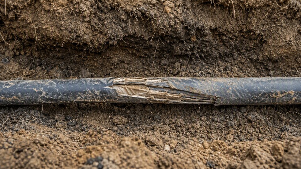
Chemical attack on jackets, sheaths, and seals
Chemical exposure is very site-specific, which is why “direct burial rated” should not be read as “safe in any soil.” Cable jackets and sheaths are chosen against expected exposure, not against every contaminant a plant may have in the ground.
Potential chemical threats include:
- Hydrocarbons from fuel farms, workshops, generator pads, transformer oil leaks, and old underground tanks.
- Fertilizers and agricultural chemicals near irrigation systems, greenhouses, and processing facilities.
- Acids or alkalis from process drains, battery rooms, mining operations, cement plants, and chemical storage areas.
- Salts from coastal soil, de-icing runoff, brine, or saline groundwater.
- Industrial effluent, landfill leachate, and contaminated groundwater where the soil history is uncertain.
Chemical attack may soften, swell, crack, embrittle, or permeate jacket materials. Some effects are visible when a cable is excavated; others show up first as moisture ingress or sheath failure. If the route crosses a known contaminated zone, the buyer should ask for jacket compatibility information and, for larger projects, consider soil or groundwater analysis before final cable selection. A cheaper jacket can be perfectly adequate in clean soil and the wrong economy in a refinery trench.
Corrosion of conductors, shields, armor, and bonding systems
Corrosion is not limited to bare copper in wet ground. It can involve copper conductors, aluminum conductors, metallic shields, lead sheaths, steel wire armor, metallic tapes, glands, lugs, link boxes, and bonding conductors. Once corrosion starts in a hidden metallic layer, electrical performance and fault-withstand capability can degrade without an obvious surface clue.
The details matter:
- Copper generally has good corrosion resistance, but it can still suffer in aggressive soils or where stray currents are present.
- Aluminum needs compatible terminations, moisture control, and correct joint compounds; wet, contaminated interfaces can become trouble spots.
- Metallic shields and screens must remain electrically continuous to control stress and carry fault current as designed.
- Lead sheaths can perform well in some environments but are not immune to corrosion, fatigue, or installation damage.
- Steel wire armor and tapes need the right jacket protection, especially in wet, saline, acidic, or industrial soils.
- Glands and bonding systems can create galvanic couples if dissimilar metals are mixed without thought.
- Stray DC currents near rail systems, cathodic protection installations, substations, or industrial DC equipment can drive accelerated corrosion.
Galvanic corrosion needs an electrolyte and dissimilar metals with an electrical path. Buried cable routes often provide all three if water, salts, and mixed hardware are present. This is why plant electricians who casually substitute glands, earth tags, or bonding jumpers from whatever is on the shelf can create a long-term reliability problem even though the installation passes the first energization test.
Mechanical stress does not stop after backfilling
Mechanical damage is not just a construction-phase issue. Crushing, rock pressure, settlement, vehicle loading, frost heave, trench movement, and long-term soil creep can keep working on a buried cable for years.
Common mechanical aging causes include:
- Sharp stones or demolition rubble pressing into the jacket after compaction.
- Insufficient bedding below the cable, leaving point loads under the sheath.
- Traffic loading from forklifts, trucks, cranes, or container handling equipment above shallow routes.
- Settlement near trenches, culverts, embankments, tanks, or newly filled ground.
- Frost heave in cold regions, especially where water migration changes soil volume.
- Improper bending radius at entries, pits, poles, and transformer pads.
- Excess pulling tension that stretches conductors, distorts insulation, or damages shields.
- Long unsupported vertical drops or poorly clamped risers that transfer stress into terminations.
Mechanical protection normally has a cost and thermal penalty. Concrete slabs, ducts, tiles, or deeper burial can reduce strike and crushing risk, but ducts and tight protection arrangements can make heat dissipation worse if the design is not recalculated. The preferred choice flips in high-traffic yards, road crossings, and utility corridors, where mechanical survival may dominate and ampacity must be designed around the protection method rather than assumed from a free-buried rating.
Biological damage and site-specific ground conditions
Biological attack is easy to dismiss until a route crosses the wrong area. Rodents can chew jackets, especially at entries, pits, and soft ground transitions. Termites and insects may damage certain polymeric materials or use cable routes as protected pathways. Roots can displace cables, open joints, or create moisture pockets. Microbial activity can contribute to corrosion in some soils, particularly where sulfate-reducing bacteria or organic contamination are present.
Not every site needs armor for biological protection. A clean urban utility trench is different from a plantation, irrigation field, landfill edge, grain facility, or rural pump station. The engineering question is not “can animals damage cable?” but “does this route give them access, shelter, and time?” Where the answer is yes, jacket selection, armor, conduit sections, sealed entries, and inspection chambers should be specified deliberately.
Ultraviolet exposure before burial
Direct burial cable can lose part of its service life before it ever enters the trench. Drums left outdoors for months with damaged lagging, open cable ends, or no UV protection may experience jacket chalking, cracking, moisture entry, or contamination. This is especially irritating because it is preventable with basic storage discipline.
Good receiving and storage practice should include:
- Keeping drum lagging intact until installation.
- Sealing cable ends immediately after cutting.
- Storing drums off standing water and corrosive ground.
- Avoiding prolonged direct sunlight unless the jacket and packaging are suitable for it.
- Rotating inventory so older drums do not sit forgotten behind the maintenance shop.
- Inspecting for jacket damage before pulling, not after the trench is closed.
Procurement teams sometimes focus hard on cable price and then let expensive material sit in a yard like scrap. That is not a supplier problem or an engineering problem; it is a handover problem.
Joints and terminations often age first
The accessory work is where many buried systems become fragile. A factory-made cable core is produced under controlled extrusion, curing, shielding, and testing conditions. A joint bay, trench, or temporary shelter is not the same environment. Dust, rain, poor lighting, rushed outage windows, dull stripping tools, and one missing cleaning wipe can all matter.
Joints and terminations may fail early because of:
- Poor moisture sealing at the outer jacket or gland.
- Incorrect stress control on medium-voltage terminations.
- Incompatible joint kits for the insulation, screen, conductor size, or voltage class.
- Wrong crimp die, poor compression, or contaminated conductor surfaces.
- Sharp insulation cuts during stripping.
- Inadequate screen continuity or bonding.
- Resin mixing errors, cold-shrink mishandling, or heat-shrink overheating.
- Lack of mechanical support where cable movement loads the accessory.
For many buried cable projects, the practical reliability limit is set by the worst joint, termination, or damaged section, not by the nominal life of the cable construction. That boundary matters: if the route is short, continuous, chemically benign, thermally conservative, and installed by a disciplined crew, the cable design itself may dominate service life. Once the route includes multiple field joints, contaminated soil, heavy loading, or unknown backfill, the aging risk moves from the datasheet into the trench record, inspection practice, and workmanship control.
Installation factors that cut life
A cable that should have lasted 30 or 40 years can be damaged in one afternoon by a bad trench, an over-tight pull, a wet joint, or undocumented routing. Most premature direct burial failures I have seen trace back less to the cable catalog rating and more to installation conditions that were never recorded, inspected, or tested before energization. The product still matters, but the trench becomes part of the cable system.
Trench design
Depth is the first obvious item, but it is not the only one. Many residential or light-duty circuits are installed around 450 to 600 mm deep where local rules allow it, while industrial, utility, road-crossing, and medium voltage feeders often sit around 750 to 1,200 mm or deeper. The actual requirement comes from the local electrical code, utility standard, road authority, or project specification, not from a general rule of thumb.
A good trench has:
- Adequate depth for the voltage class, mechanical exposure, frost line, and future grading work.
- Enough width to place the cable without dragging it against the sidewall.
- A stable bottom profile without sudden high points, broken concrete, rebar ends, or rock ledges.
- Drainage control where the route crosses low areas, clay pockets, or waterlogged ground.
- Required separation from gas, water, steam, communication, and other power services.
- Warning tape or detectable marker tape at the specified height above the cable.
- Route marker posts, surface plates, or electronic marker systems where future excavation is likely.
The mechanism is simple: a cable lying on a point load ages differently from one supported evenly. Soil settles, the cable heats and cools under load, traffic loads pass down through the ground, and the jacket is slowly pressed against whatever it was laid on. A sharp stone that looked harmless during backfill can become the starting point for jacket damage, moisture ingress, and eventually insulation stress.
Bedding and backfill
Bedding is not cosmetic. Sand, screened native soil, selected fill, or engineered thermal backfill may be required depending on the cable design, ampacity calculation, soil thermal resistivity, and mechanical exposure. In heavier industrial work, I do not like seeing “whatever came out of the trench” pushed straight back in by a loader unless the specification clearly permits it and the material has been checked.
Bad backfill shortens life through three main paths:
- Mechanical damage: sharp rock, scrap steel, broken brick, concrete chunks, and trench debris cut or bruise the jacket.
- Thermal restriction: dry, loose, highly resistive soil traps heat and raises conductor temperature under load.
- Settlement and voiding: uncontrolled compaction creates uneven support, bending stress, and water pockets.
There is a trade-off here. Free-draining coarse material can reduce standing water, but it may have poor thermal performance or contain sharp aggregate. Fine thermal backfill can improve ampacity consistency, but it costs more, needs correct compaction, and may not suit every drainage condition. The preferred choice flips when the dominant risk changes from thermal overload to mechanical exposure or chronic water accumulation.
Pulling and laying practice
Cable damage during installation is often invisible. The jacket looks acceptable, the continuity test passes, and the problem appears years later as insulation resistance drift, sheath leakage, or a fault at a bend.
Control the basics:
- Do not exceed manufacturer pulling tension limits for the conductor or pulling eye.
- Watch sidewall pressure at bends, especially in ducts, sweeps, and trench turns.
- Respect the minimum bend radius during pulling and final placement.
- Avoid twisting, basket-weave kinks, and reel “dumping” onto the ground.
- Store and unreel drums correctly; damaged flanges and nails through lagging are not rare on busy sites.
- Check minimum installation temperature, because cold jackets and insulation are less forgiving.
- Use rollers, bell mouths, quadrant blocks, and guides instead of dragging cable over trench edges.
One practical warning: a cable pulled nicely for the first 80 meters can be ruined in the last 10 meters if the crew tries to “make the corner” by hand with a backhoe bucket holding tension. That kind of abuse rarely shows up in procurement documents, but it shows up later in maintenance budgets.
Splices, joints, terminations, and water entry points
Direct burial joints must be rated for underground moisture exposure, matched to the cable size and insulation type, and installed by trained personnel using the correct tooling. A joint kit that is acceptable in a dry cabinet is not automatically acceptable in saturated soil. Compatibility matters: conductor material, screen construction, insulation diameter, jacket type, voltage class, and environmental sealing all affect the joint design.
Terminations deserve the same attention. Water often enters at transitions rather than through the middle of the cable run:
- Risers from direct burial to conduit.
- Pad-mounted transformers and switch cabinets.
- Handholes, vaults, and draw pits.
- Building entries and foundation penetrations.
- Pole bases and lighting columns.
- Conduit ends where no effective sealing gland or compound was installed.
Once water migrates along a conductor strand, screen, or imperfect jacket interface, it can bypass a surprising amount of otherwise good cable. For medium voltage systems, poor stress control at terminations and joints can also raise local electrical stress and increase the risk of partial discharge activity.
A direct burial cable joint should be selected for the cable construction, voltage class, conductor size, insulation system, and wet underground environment, not just for conductor continuity.True
Underground joints must maintain electrical insulation, environmental sealing, mechanical protection, and, for shielded medium voltage cables, correct screen and stress-control performance. A simple conductive connection is not enough for long service life.
Thermal grouping errors
Ampacity calculations on paper can be defeated in the trench. Multiple loaded circuits in one trench heat each other. Duct banks reduce heat dissipation compared with direct soil contact. Crossings near steam lines, district heating, process drains, or sun-heated concrete yards can raise the local thermal envelope.
Typical installation checks should include:
- Number of circuits in the trench and their load profiles.
- Spacing between circuits and duct groups.
- Soil thermal resistivity assumptions used in the design.
- Seasonal soil moisture changes, especially in dry climates.
- Simultaneous loading during peak plant operation.
- Transitions through conduit, sleeves, or building entries where heat cannot escape as easily.
Continuous conductor temperature ratings are commonly 70, 90, or 105°C depending on cable design, but those numbers are not permission to run hot everywhere, all the time. Sustained operation above the intended thermal envelope accelerates insulation aging, dries surrounding soil, and can create a feedback loop: hotter cable, drier soil, poorer heat transfer, still hotter cable.
Mechanical protection zones
The required protection changes with the land use above the cable. A feeder under a landscaped verge is not exposed like a feeder through a port yard, mine road, or solar farm where trench lines get crossed by trenchers, pile drivers, augers, forklifts, harvesters, and maintenance trucks.
Consider extra protection in:
- Road and rail crossings.
- Farm machinery routes and irrigation work zones.
- Construction staging areas and future expansion corridors.
- Ports, mines, quarries, and heavy industrial yards.
- Solar farms, wind projects, and substations with frequent civil works.
- Areas with shallow rock where depth cannot be maintained.
- Entrances to buildings, cabinets, transformer pads, and pole bases.
Protection may mean conduit, concrete slabs, cable tiles, steel plates, armored cable, deeper burial, route markers, or a combination. The trade-off is access and heat. Conduit and slabs improve mechanical protection, but they can complicate pulling, reduce heat dissipation, and make later fault location or repair slower unless the route is well designed.
Post-installation testing and records
Before energization, the minimum inspection package should be agreed in the project quality plan. For low voltage work, continuity, phase identification, insulation resistance, and basic sheath or jacket checks may be appropriate. For medium voltage systems, very low frequency testing, sheath integrity testing, and partial discharge testing may be specified, depending on the cable type, accessories, owner standard, and applicable test procedures.
Testing is not just about passing the job. It creates a baseline. A clean insulation resistance value, sheath test result, VLF record, or partial discharge report gives the maintenance team something to compare against after flooding, excavation, overload events, or unexplained trips. The exact test voltage, duration, acceptance limits, and suitability for the cable design must be verified against the current cable and accessory documentation and the applicable standard.
As-built documentation is part of reliability, not paperwork for the archive. Keep:
- Route drawings tied to fixed site references.
- Joint and termination locations.
- Burial depth records at key points and crossings.
- Test reports and commissioning data.
- Photos before backfill, especially at bends, joints, crossings, and entries.
- GPS coordinates where site practice supports it.
- Notes on ducts, slabs, warning tape, spare conduits, and marker systems.
Years later, the crew with a mini-excavator will not know what the original installer intended. Good records turn a buried cable from a hidden liability into a maintainable asset.
Construction choices that extend life
The longest-lasting direct burial cable is not simply the “heaviest” or most expensive option; it is the construction that matches the soil, load current, fault duty, installation method, and termination environment. For procurement, the useful question is not “premium or standard?” but which conductor, insulation, jacket, water barrier, armor, screen, and accessory system removes the dominant failure risk on that route.
Conductor selection: copper and aluminum are both valid, but not interchangeable
Copper gives higher conductivity in a smaller cross-section, better tolerance of compact terminations, and usually simpler acceptance by installers. Aluminum reduces weight and material cost, which matters on long feeders, large trench pulls, and projects where drum handling is a real constraint. The trade-off is that aluminum typically needs a larger conductor size for the same ampacity and voltage drop, and it demands more disciplined termination practice.
In plant work, I have seen aluminum perform very well when the lugs, joint sleeves, oxide inhibitor, compression dies, and torque procedure were specified as a system. I have also seen nuisance heating at terminations where someone treated aluminum like copper and used the nearest lug in the stores cabinet. That is not a conductor failure; it is a procurement and installation control failure.
Key selection checks include:
- Conductivity and voltage drop: copper carries more current per unit area; aluminum may need upsizing.
- Weight and pulling: aluminum can reduce drum weight and pulling load, useful on long trench sections.
- Corrosion risk: both metals need compatible connectors and sealed accessories; aluminum is less forgiving where moisture enters terminations.
- Mechanical handling: copper is tougher under repeated bending; aluminum needs larger bend radii discipline and careful pulling tension control.
- Total installed cost: aluminum may win on cable cost, but the saving can shrink after upsizing, special lugs, labor training, and spare accessory control.
Insulation system: temperature rating is only one part of the decision
XLPE, tree-retardant XLPE, EPR, PVC, and other compounds age differently underground because heat, moisture, electrical stress, and mechanical strain attack different parts of the polymer system. A 90 degrees Celsius rated insulation, for example, does not mean the cable should be run near 90 degrees Celsius as normal plant practice if the owner expects long life and stable dielectric margin.
Common insulation choices are usually evaluated like this:
| Insulation type | Where it tends to fit | Life-extension value | Watch points |
|---|---|---|---|
| XLPE | Low voltage and medium voltage power cables | Good dielectric strength and thermal performance; common 90 degrees Celsius class designs | Less flexible than EPR; water-tree resistance depends on compound and design |
| Tree-retardant XLPE | Medium voltage feeders, wet soils, utility-style installations | Better resistance to water treeing than standard XLPE when designed and tested properly | Usually higher cost; must be tied to the relevant cable standard and test regime |
| EPR | Industrial feeders, mining-style service, applications needing flexibility | Good flexibility, moisture tolerance, and thermal behavior in many designs | Larger diameter or different electrical parameters may affect accessories and ampacity |
| PVC | Some low voltage direct burial or sheathed constructions | Economical, processable, familiar in many markets | Lower high-temperature performance than XLPE or EPR in many designs; plasticizer and low-temperature behavior need checking |
| Specialty thermoset or thermoplastic systems | Chemicals, hydrocarbons, high temperature, special fire requirements | Can solve a specific environmental limit | Requires project data; do not buy by compound name alone |
The mechanism matters. Sustained conductor temperature drives insulation oxidation and polymer chain degradation; moisture plus electrical stress can initiate water trees in medium voltage insulation; poor compatibility between insulation and semi-conductive screens can create stress concentrations. The preferred choice flips when the limiting factor changes: dry industrial soil with high load may favor thermal margin, while a wet MV feeder may justify tree-retardant XLPE or another tested moisture-resistant system even at a higher purchase price.
A higher continuous conductor temperature rating does not automatically mean a longer service life if the cable is operated hotter.True
Higher-rated insulation can tolerate higher operating temperature within its design basis, but thermal aging generally accelerates as operating temperature rises. Long life depends on actual load profile, soil thermal resistivity, burial depth, grouping, and installation quality.
Jacket, water blocking, and mechanical protection should be selected together
A buried cable jacket is not just a cosmetic outer layer. It is the first defense against abrasion during pulling, stones in backfill, water migration, chemicals, sunlight before burial, termites in some regions, and occasional rough handling by people who are trying to finish a trench before rain starts.
Typical jacket choices include:
- PE jackets: strong moisture resistance and abrasion performance; often good for direct burial but usually weaker on flame behavior.
- PVC jackets: economical and widely accepted; flame behavior can be better than PE, but moisture, chemical, and low-temperature performance depend on formulation.
- LSZH compounds: useful where smoke and halogen acid gas at building entries, tunnels, or enclosed routes are a concern; may not be the best pure burial jacket unless specified for that duty.
- Chlorinated or specialty compounds: selected for oil, chemical, sunlight, flame, or industrial contamination exposure where ordinary PVC or PE is not enough.
- Termite-resistant or anti-rodent compounds: relevant only where biological attack is a known local risk and the compound is supported by suitable project documentation.
Water blocking should be matched to the consequence of water entry. Longitudinal barriers limit water travel along the cable if the jacket is damaged. Swelling tapes, swelling powders, and filled conductor strands help stop migration through conductor interstices or screen areas. Radial barriers, such as laminated sheaths or metallic moisture barriers, resist water entering through the cable wall in the first place.
A practical rule: use more aggressive water blocking where joints are far apart, outage cost is high, soil stays wet, or the circuit is medium voltage. The cost is not only the cable price. Filled or heavily blocked constructions can affect stripping, joint preparation, and accessory cleanliness, so the jointing method needs to be agreed before purchase.
Mechanical protection has the same logic:
| Protection method | Main use | Practical limitation |
|---|---|---|
| Steel wire armor | Tensile and impact protection; common for industrial direct burial | Heavier, magnetic losses may matter in single-core AC layouts |
| Aluminum wire armor | Mechanical protection with lower weight and nonmagnetic behavior | Lower mechanical strength than steel in some designs |
| Steel tape armor | Crush and localized impact protection | Less suitable where high pulling tensile load is expected |
| Corrugated metallic sheath | Moisture barrier plus mechanical protection in some cable systems | Accessory and bonding details become more critical |
| Nonmetallic armoring | Corrosion resistance and nonmagnetic behavior | Must be checked for crush, impact, rodents, and installation method |
| Conduit, ducts, tiles, or slabs | Route-level protection against excavation and surface loads | Adds installation cost and may reduce heat dissipation |
This is where cable design and civil design meet. A tough armored cable in poor rocky backfill can still be damaged; a non-armored cable under warning tape and protective slabs may outlast it if the route is controlled, thermal backfill is correct, and future excavation risk is managed.
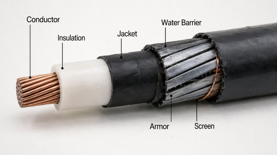
Screens, bonding, accessories, and standards decide whether the design works as a system
For medium voltage cables, shielding and screens are not optional decoration. Conductor screens smooth the electric field at the conductor surface. Insulation screens control the field at the insulation boundary. Copper tape screens, copper wire screens, concentric neutrals, and metallic sheaths provide fault current path, touch voltage control, and electromagnetic behavior depending on the system design.
Bonding is the part that gets underestimated. Single-point, both-end, or cross-bonded screen arrangements affect circulating currents, sheath voltage, losses, and safety. The correct answer depends on route length, load current, fault level, earthing system, and local practice. If procurement buys the cable before engineering has confirmed screen area and bonding method, the project may inherit either unnecessary losses or insufficient fault capacity.
Accessory compatibility must be locked down with the cable construction:
- Glands and cleats must suit cable diameter, armor type, and short-circuit forces.
- Lugs and connectors must match conductor material, class, and stranding.
- Joints and terminations must match insulation diameter, screen type, jacket material, and voltage class.
- Heat-shrink and cold-shrink kits must be approved for the cable geometry and service environment.
- Sealants, armor earthing kits, screen wires, and grounding components must be specified, not left to site improvisation.
Standards provide the test basis, but the applicable family depends on market and application. IEC, BS, VDE, ICEA, UL, CSA, NEC, IEEE, or national project standards may control construction, flame tests, voltage tests, burial practice, ampacity calculation, and installation inspection. The boundary of any recommendation in this section is the governing project standard and the actual route condition; a design that is correct for an IEC industrial feeder may not be acceptable for a North American utility specification or a building-code-controlled transition.
Fire and smoke requirements often change along the route. Direct burial portions may prioritize moisture, impact, and soil chemical resistance, while building entries, tunnels, risers, substations, or cable basements may require flame-retardant, low-smoke, or low-halogen performance. That can mean multiple cable types, transition joints, sleeves, ducts, or fire-stopping details rather than forcing one jacket compound to do every job badly.
For Jinda, the relevant manufacturing point is not a slogan about “quality cable.” Long service life depends on controlled compounds, conductor processing, extrusion discipline, water-blocking application, armor formation, routine testing, documentation, and engineering communication before the order is released. With integrated R&D, production, testing, technical support, and after-sales service across its manufacturing system, Jinda can support project-specific construction review, but the buyer still needs to provide the route conditions, applicable standard, load data, installation method, and accessory requirements early enough for the cable design to be engineered rather than guessed.
Warning signs and diagnostic tests
Buried cable rarely gives one neat warning before failure. In practice, you build the picture from operating symptoms, accessible inspection points, electrical trends, and the cable’s age and construction. The useful question is not only “did it pass the test today?” but “is the circuit moving toward failure faster than expected?”
Operational symptoms worth investigating
Treat repeated small disturbances as evidence, not as nuisance noise. The common early warnings include:
- Nuisance tripping of breakers, RCDs, ground fault relays, or feeder protection without a clear load-side cause.
- Ground fault alarms that reset and return, especially on wet mornings or after irrigation cycles.
- Rising leakage current on monitored circuits, even if it remains below the trip threshold.
- Voltage imbalance between phases where load distribution has not changed.
- Unexplained load interruptions, motor contactor dropouts, PLC power dips, or feeder recloser operations.
- Intermittent faults after rain, thaw, or flooding, which often point toward sheath damage, water ingress, or contaminated joints.
- Localized heating at terminations, lugs, glands, or joint cabinets caused by loose connections, corrosion, undersized terminations, or conductor strand damage.
The mechanism is usually simple: moisture and contamination reduce insulation resistance, leakage current rises, local heating increases, and the higher temperature accelerates insulation aging. That loop may run quietly for months before it becomes a permanent fault.
Visual inspection points before bringing out the test set
Most direct burial cable cannot be seen, so inspect the places where underground damage shows itself above ground. A five-minute walkdown sometimes saves a day of blind testing.
Check:
- Exposed risers, elbows, conduits, and building entries for UV cracking, impact marks, missing seals, or pulled glands.
- Cabinets, junction boxes, switchgear entries, manholes, and handholes for water, silt, corrosion, insect nests, and damaged boots.
- Joints and splices for swelling, tracking marks, cracked resin, softened tape, or evidence of overheating.
- Cable glands and termination plates for looseness, corrosion, and poor strain relief.
- Trench markers, route posts, warning tape locations, and as-built drawings against the actual site.
- Surface settlement, patched pavement, new fence posts, anchor bolts, drainage work, or landscaping that may have disturbed the route.
- Rodent activity near risers and pits.
- Excavation damage: scraped jackets, crushed conduits, exposed armor, bent cable, or unsealed temporary repairs.
- Water pooling above the cable route, especially where backfill has settled or drains have been rerouted.
Basic electrical tests
Start with tests that match the voltage class, cable design, and risk tolerance. For low voltage circuits, the usual first checks are:
- Continuity testing to confirm open conductors, broken neutrals, or poor joints.
- Insulation resistance testing between conductors and to earth, using a test voltage suitable for the cable and connected equipment.
- Polarization index, where applicable, mainly on larger insulation systems where absorption behavior is meaningful.
- Conductor resistance checks to detect high-resistance joints, damaged strands, or unexpected conductor length.
- Comparison against baseline values, commissioning records, sister circuits, and previous maintenance readings.
Single insulation resistance values can mislead. A cable in dry soil may look acceptable during a summer shutdown and degrade sharply during the wet season. Trend charts, test temperature, recent weather, circuit loading, and cable length all matter.
Sheath and jacket integrity tests
Outer sheath testing is valuable because the sheath is the first defense against water, soil chemistry, and mechanical contact. A defect in the jacket may not have reached the primary insulation yet, especially on screened or armored designs, but it gives moisture a path toward the metallic screen, armor, or insulation system.
For critical feeders, sheath fault testing and location can identify pinholes, cuts, crushed areas, and installation damage before the circuit becomes an electrical failure. The trade-off is access and planning: sheath testing may require isolation, correct bonding arrangements, and technicians who understand the cable construction. It is not a casual “megger everything and see what happens” exercise.
Medium voltage diagnostics
Medium voltage cable needs a more deliberate diagnostic plan. Common tools include:
- Very low frequency withstand testing to prove the cable can survive a defined overvoltage stress, where suitable for the insulation type and project standard.
- Tan delta testing to assess dielectric losses and water treeing tendencies in certain insulation systems.
- Partial discharge testing to identify voids, defects, poor terminations, or joint problems that create localized electrical stress.
- Time domain reflectometry to estimate distance to impedance changes, opens, shorts, or some joint defects.
- Fault location methods, such as surge generators, sectionalizing, acoustic pinpointing, and bridge methods, selected according to fault type and site conditions.
Test choice should match cable age, insulation material, shielding system, termination design, and the consequence of failure. An old cable that has carried a plant for 30 years may not be the right candidate for an aggressive withstand test unless the owner accepts that the test could force a weak point to fail under controlled conditions.
Thermal assessment
Electrical tests do not replace thermal review. A direct burial circuit running near its limit can age quickly even when insulation resistance looks acceptable.
Assess:
- Actual load profile, not only nameplate current.
- Seasonal peaks, harmonic heating, and phase imbalance.
- Infrared images of accessible terminations, lugs, glands, and bus connections.
- Torque condition and corrosion at terminations.
- Ampacity assumptions used in the original design.
- Soil thermal resistivity assumptions, especially under pavement, dry sand, ducts, compacted fill, or grouped feeders.
Continuous conductor ratings such as 70, 90, or 105°C depend on cable design, but sustained operation near or above the intended thermal envelope shortens insulation life. The boundary is clear: thermal conclusions are only as good as the load data and soil assumptions behind them.
Interpreting records without fooling yourself
Good maintenance teams keep readings in context:
- Same test method.
- Same or corrected temperature.
- Same test duration.
- Same cable section isolated.
- Weather and ground condition noted.
- Recent faults, overloads, repairs, or excavation recorded.
A pass result is useful. A pass result with steadily falling insulation resistance, rising leakage current, worsening tan delta, or recurring wet-weather alarms is a warning.
When not to over-test
Do not let testing become the cause of failure. Aggressive or inappropriate high-voltage testing on aged, wet, or mechanically damaged cable can push marginal insulation over the edge. That may be acceptable during a planned outage with spares and repair crews ready; it is poor practice on a critical feeder feeding production with no bypass.
The test plan should be selected by qualified engineers or competent cable test specialists using the current cable manual, applicable standards, circuit criticality, and site conditions. For older direct burial assets, the best approach is often staged: inspect first, review operating history, run low-risk measurements, then decide whether advanced diagnostics or controlled replacement planning makes more sense.
Maintenance and replacement planning
Direct burial cable should be managed as a buried asset, not as a consumable that is forgotten until it trips a feeder. The practical plan is to document what is underground, test enough to see the trend, stock the repair parts that would stop production, and time replacement around outages and civil work rather than around the calendar alone.
Build a cable asset register before the first fault forces people to guess. For a factory, solar farm, port, mine, or utility network, the register should include:
- Cable type and construction, including insulation, sheath, armor or screen design where applicable
- Voltage rating, conductor size, conductor material, and number of cores
- Route drawing, burial depth where known, route length, crossings, and nearby services
- Installation date, installer, pulling records if available, and commissioning test results
- Joint, termination, lug, gland, and accessory locations
- Test history, including insulation resistance, VLF, tan delta, partial discharge, sheath tests, or continuity checks as applicable to the voltage class
- Loading profile, including normal load, seasonal peak load, motor starting duty, harmonic exposure, and emergency loading
- Circuit criticality: production feeder, fire pump, security system, export line, lighting, irrigation, standby supply, or non-critical service
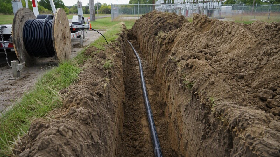
Inspection intervals should follow risk, not age alone. A ten-year-old cable in dry, stable sand with conservative loading may deserve less attention than a three-year-old feeder installed through wet clay, chemical runoff, or a truck crossing with poor compaction. Circuits need higher attention if they have:
- Standing water in pits, handholes, or ducts entering buried sections
- Acidic, saline, oily, or chemically contaminated soil
- Sustained high loading near the cable thermal rating
- Heavy vehicle traffic, ground settlement, or repeated excavation nearby
- Previous sheath damage, joint failures, or unexplained trips
- Missing route records or undocumented repair joints
Baseline and trend testing turn maintenance from guesswork into asset management. One insulation resistance value taken after a rainstorm does not tell the whole story; the useful information is whether readings, dielectric loss, sheath leakage, or partial discharge activity are stable, drifting, or accelerating. The mechanism is straightforward: moisture ingress, insulation defects, and damaged screens usually do not move from healthy to failed in a neat straight line, but trending catches the point where deterioration is no longer just background aging.
For critical circuits, stock spares based on outage consequence and supply lead time. That usually means enough cable for a credible repair length, compatible joints, lugs, terminations, glands, heat-shrink or cold-shrink kits, screen bonding materials, and the correct tooling. In international projects, I have seen a small missing termination kit hold up a repair longer than the cable itself; procurement teams should treat accessories as part of the cable system, not as loose site consumables.
When a fault appears, compare partial replacement with full route renewal. Partial repair can be the right call where the cable is young, the cause is local mechanical damage, access is easy, and the remaining route tests cleanly. Full renewal starts to look better when the cable is near its design life, has multiple joints, poor documentation, repeated wet-section faults, undersized conductors for future load, or a route that will be excavated anyway for plant expansion.
Civil work often dominates lifecycle cost. Excavation permits, traffic control, concrete cutting, reinstatement, shutdown labor, lockout planning, testing, and recommissioning can cost more than the cable drum sitting in the yard. The cheapest cable replacement is usually the one coordinated with a planned outage and the next civil works package, not the one triggered by a midnight feeder failure.
Feed maintenance data back into the next purchase specification. If the old route failed from sheath damage in rocky backfill, buying the same cable again with a better price does not solve the problem; the next specification may need stronger mechanical protection, different bedding, improved water blocking, route markers, or redesigned joints. If the failure driver was thermal overload, the answer may be conductor sizing, route spacing, load management, or a higher-temperature cable design verified against the actual installation conditions.
Specification evidence buyers should request
Treat the cable offer as an engineering submittal, not just a price line. Before placing a direct burial cable order, ask the supplier to provide a document package that proves the design matches the route, soil, voltage system, installation method, and destination-market requirements.
A practical buyer’s evidence pack should include:
- Applicable standard and product identity
- Applicable manufacturing standard, such as the project-specified IEC, BS, AS/NZS, ICEA, UL, CSA, or local utility specification.
- Product datasheet and construction drawing.
- Rated voltage, conductor material, conductor class, conductor cross-section, insulation type, jacket material, armor or metallic screen design, and outer diameter.
- A clear statement that the cable is suitable for direct burial under the stated installation conditions.
- Routine, sample, and type test evidence
- Conductor resistance.
- AC or DC voltage withstand test, according to the relevant standard.
- Insulation thickness and jacket thickness checks.
- Tensile strength, elongation, hot set, aging, and other mechanical or thermal performance tests where required by the standard.
- Spark testing on non-metallic sheaths where applicable.
- Drum-by-drum routine test records for large orders, not only a generic catalogue certificate.
- Medium voltage verification
- Partial discharge test results and the specified test voltage.
- Conductor screen, insulation screen, and metallic screen construction.
- Evidence of insulation cleanliness and extrusion process control.
- Water-tree resistance or longitudinal water-blocking performance where the project specification requires it.
- Compatibility with terminations, joints, separable connectors, and earthing arrangements. A good MV cable can still fail early if accessories are mismatched or installed outside their stress-control limits.
- Route and soil assumptions
- Thermal resistivity assumptions used for ampacity.
- Soil chemical exposure limits, including hydrocarbons, salts, acids, alkalis, and aggressive groundwater.
- Minimum bend radius, maximum pulling tension, sidewall pressure limits, and permitted installation temperature.
- Requirements for bedding, backfill, warning tape, duct sections, road crossings, and separation from heat sources.
- Commercial and logistics controls
- Drum size, drum direction, gross weight, and handling points.
- Manufacturing length tolerance and allowed joint policy.
- End sealing method, export packing, moisture protection, storage position, and maximum outdoor storage duration.
- English marking on cable sheath, drum labels, packing list, and traceability documents.
For international bulk procurement, settle inspection rules before production starts. Define whether the buyer, a third-party inspector, or the end user will witness factory acceptance testing, review raw material records, and issue release notes. Ask for certificates of conformity, quality management documentation, and destination-market compliance documents where required.
Scale matters when repeat orders are expected. Jinda’s five production bases, large manufacturing footprint, integrated technical support, and export experience across more than 50 countries are relevant because long-life cable projects often need repeatable construction, consistent marking, responsive documentation, and supply continuity years after the first shipment.
Frequently asked questions
Can direct burial cable be installed in conduit?
Yes, if the cable design and local code allow it, but conduit does not automatically make the installation “better.” It changes the job in four practical ways:
- Heat dissipation: cable in conduit may run warmer than the same cable in direct contact with suitable soil, especially in long loaded feeders or duct banks.
- Pulling stress: the cable must tolerate the pulling tension, sidewall pressure, and bend radius used during installation.
- Water behavior: underground conduit often fills with water over time. The cable still needs wet-location suitability, and the conduit system needs proper drainage or sealing where specified.
- Inspection and code treatment: ampacity, burial depth, conduit fill, grounding, and transition protection may all be governed differently than a direct-buried installation.
For short protective sleeves under roads, walls, or slab edges, conduit is common. For an entire feeder route, engineering review matters.
Is armored cable always better underground?
No. Armor improves resistance to shovel damage, stones, rodents, and some crushing loads, but it brings its own engineering and commercial costs.
The buyer should check:
- whether the armor material suits the soil corrosion risk;
- whether the armor must be bonded or grounded;
- whether terminations and glands are available and rated for the environment;
- whether the extra weight affects handling, drum size, pulling method, and labor;
- whether the project really needs armor or would be better served by bedding, warning tape, conduit at crossings, or route protection.
Armor is valuable where mechanical risk is credible. In benign soil with controlled trenching and no future excavation risk, it may simply add cost and installation complexity.
Does deeper burial always increase cable life?
No. Greater depth usually reduces damage from vehicles, gardening tools, frost movement, and casual excavation, but it can also make the cable run hotter and harder to repair.
Deep burial may expose the cable to:
- wetter soil layers or poor drainage;
- higher thermal resistance if backfill is compacted badly or dries out seasonally;
- longer fault-location and excavation time;
- more expensive repairs around roads, foundations, or other buried services.
Depth should be selected from code, voltage level, traffic loading, soil conditions, and thermal design, not from the idea that “deeper is always safer.”
Can a cable be repaired after a fault?
Often, yes. A localized fault can sometimes be cut out and repaired with a correctly rated underground joint kit, installed by trained jointers under clean, dry, controlled conditions.
Replacement becomes more sensible when:
- faults are repeated along the same route;
- insulation test results show general aging, not one isolated defect;
- water has migrated along the conductor or screen;
- joints are inaccessible or already numerous;
- the feeder is critical enough that another outage would cost more than replacement.
A repair joint is part of the cable system after it is installed. A poor joint is just a delayed second failure.
How often should buried cables be tested?
Testing intervals depend on voltage, criticality, environment, loading history, and the maintenance standard used by the owner. A low-voltage landscape circuit and a medium-voltage plant feeder should not be treated the same.
Typical triggers for testing include:
- commissioning before energization;
- after excavation or suspected mechanical damage near the route;
- after flooding, ground movement, or repeated nuisance trips;
- during planned shutdowns for critical production feeders;
- before extending load on an older circuit.
For medium-voltage assets, testing methods and limits should be selected against the cable type, insulation system, age, and current standards. Applying the wrong test can create more risk than it removes.
What is the biggest cause of early failure?
There is no single universal cause, but the repeat offenders are familiar: installation damage, poor joints, water ingress, unsuitable cable selection, and thermal overload.
Most early direct burial cable failures are caused by the installed system and operating environment, not simply by the calendar age of the cable.True
A cable with suitable materials can still fail early if it is kinked during pulling, bedded in sharp rock, overloaded thermally, joined poorly, or exposed to water paths the design did not account for.
In practice, I would rather see an ordinary but correctly specified cable in a clean trench than a premium cable dragged over rubble, bent too tight at the riser, and buried with no route record.
Can a direct burial cable last 50 years?
Yes, it can, but only under favorable conditions: robust cable design, compatible soil, controlled installation, stable loading, good joints, and sensible maintenance. Premium industrial or medium-voltage systems may reach that range, but it should not be assumed from the words “direct burial” alone.
For purchasing, ask for the cable construction, applicable test reports, installation recommendations, thermal rating, water-blocking details if needed, and evidence that the design matches your soil, voltage, load, and route risk. A 50-year expectation is an engineering target, not a catalog promise.
Verify your burial cable specification
The useful buying question is not simply “How long will this direct burial cable last?” It is whether the proposed cable design, soil, trench method, load profile, joints, terminations, and protection details can realistically support the service life your project expects. A good cable can be made short-lived by poor backfill, chronic overload, wet accessories, or a standard mismatch at the border inspection stage.
Before approving a purchase order, verify these items as a set:
- Electrical design: rated voltage, system earthing method, conductor material, conductor size, short-circuit duty, and allowable voltage drop.
- Cable construction: insulation type and temperature rating, outer jacket material, armor or metallic screen, water-blocking design, UV exposure before burial, and rodent or mechanical protection needs.
- Burial environment: intended burial depth, soil resistivity, soil chemistry, drainage, seasonal water table, thermal backfill, road crossings, cable spacing, and nearby heat sources.
- Operating profile: normal load, peak load, duty cycle, expected future expansion, harmonic content for industrial drives, and emergency overload assumptions.
- Accessories and installation: compatible joints, terminations, glands, lugs, warning tape, ducts where required, pulling tension limits, bend radius, and sheath damage inspection.
- Compliance evidence: destination country standard, required certifications, factory test reports, type test references where applicable, packing details, drum marking, datasheet, and installation guidance.
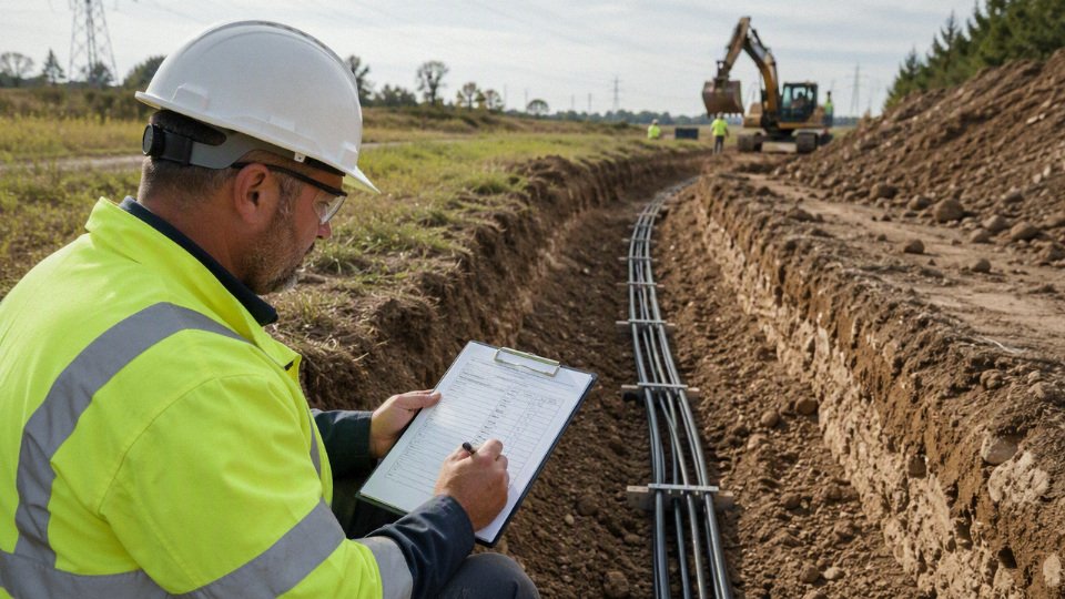
For a technical review, send project drawings or route sketches, installation environment, expected load, destination country standard, certification requirements, cable quantity, and any site constraints such as corrosive soil, flooding, road crossings, or limited trench depth. Clear photos of the route or existing failed cable help more than a long email.
Shandong Jinda Special Cable Group Co., Ltd. is set up for international direct burial cable projects: five production bases, 470,000 m² of manufacturing space, more than 1,000 employees, integrated R&D, production, sales, technical support, and after-sales service, with supply experience in over 50 countries. Before finalizing the specification, request a project-specific cable recommendation, technical datasheet, compliance document review, or quotation matched to the actual burial conditions and service-life target.