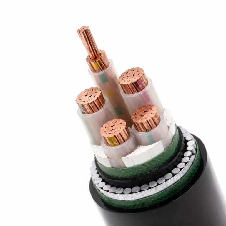
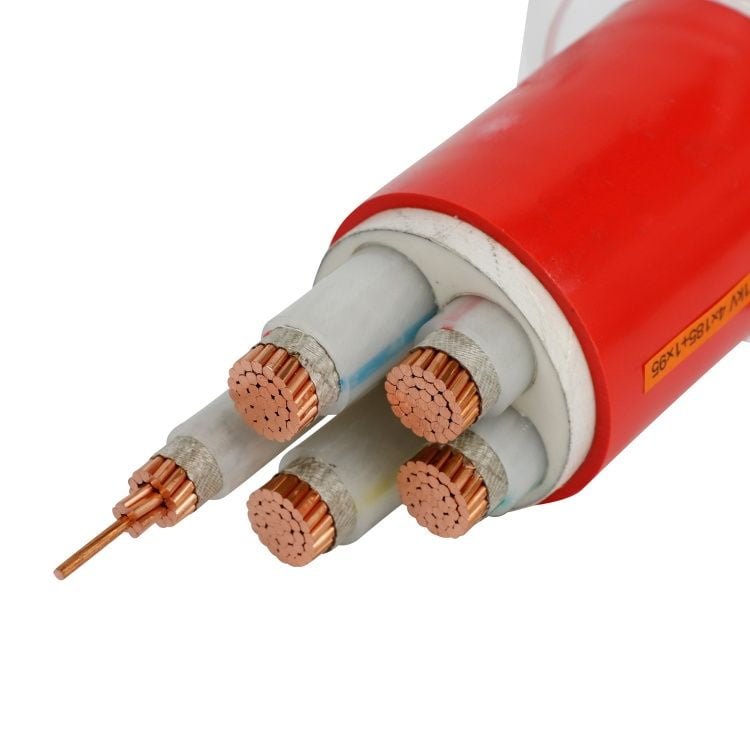
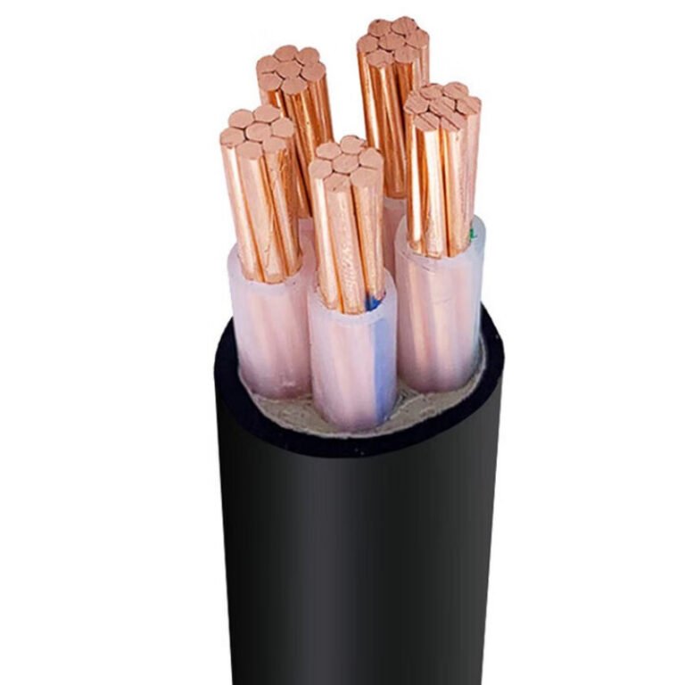
A buried feeder that was chosen only by amp rating can still fail early: water migrates through a bad jacket, soil chemistry attacks the sheath, a shallow trench gets hit by a landscaper, or voltage drop shows up after the plant adds load. The consequence is not just a tripped breaker; it can mean excavation, shutdown windows, replacement cable, inspection delays, and a repair bill far larger than the original material saving. The safer direction is to match the wiring method, burial depth, cable construction, protection, and local code before the trench is opened.
The best way to bury electrical wire underground is to use a cable or conduit system rated for wet underground service, install it at the code-required depth, protect it from physical damage, control bending and pulling stress, and verify ampacity, voltage drop, short-circuit duty, soil conditions, and local electrical authority requirements before energizing.
That sounds straightforward until the job moves from paper to dirt. A 120 V garden circuit, a farm pump feeder, and an industrial XLPE armored cable crossing a truck yard are not the same engineering problem, even if all three disappear under the ground. The details that decide service life are usually the unglamorous ones: trench bottom condition, drainage, thermal resistivity, jacket choice, warning tape location, and whether the installer respected the cable’s bend radius on a cold morning.
Burial methods compared
| Method | Where it usually fits | What you gain | What can bite you later |
|---|---|---|---|
| Direct-burial cable | Simple routes, landscape lighting, agricultural feeders, site power, remote equipment | Low installed cost, fewer fittings, faster trench work | Harder replacement, higher consequence if the route is hit or soil attacks the jacket |
| Nonmetallic conduit | Residential, commercial, light industrial, future-change routes | Pull-out replacement, defined raceway, good corrosion resistance | Water still enters; pulling limits and bends become the constraint |
| Rigid metal conduit or IMC | Driveways, exposed risers, equipment pads, traffic zones | High mechanical protection and grounding path when properly installed | Higher labor cost, corrosion control, careful bonding needed |
| Armored underground cable | Industrial plants, solar and wind farms, ports, mining, oil and gas, rodent areas | Cable-level impact and crush protection | Heavier handling, termination skill, larger bend radius |
| Concrete-encased duct bank | Multi-circuit industrial, campus, utility, and expansion-heavy installations | Organized, protectable, inspectable, expandable infrastructure | Civil cost, heat dissipation, coordination burden |
| Utility service lateral | Service entrance and metering interface | Aligns with utility ownership and approval process | Not fully controlled by the customer or contractor |
The first decision is not “which cable is cheapest?” It is whether the underground route should behave like a consumable buried asset, a maintainable raceway system, or a long-life electrical corridor. That choice drives the cable construction, trench dimensions, pulling plan, inspection points, and who has authority over the final connection.
Direct-burial cable
Direct-burial cable is appropriate where the route is simple, the cable construction is explicitly rated for soil and moisture exposure, and future replacement is not expected to be frequent. I would consider it for landscape lighting, small site power runs, agricultural buildings, irrigation controls, outbuildings, and some industrial feeders where the cable has the right jacket, armor, voltage rating, and installation protection for the soil conditions.
The mechanism is straightforward: the cable’s outer construction becomes the primary environmental barrier. In a proper direct-burial product, the jacket, bedding, insulation system, moisture resistance, and sometimes armor are selected to survive wet soil, stones, compaction, microbial exposure, fertilizers, hydrocarbons, or occasional ground movement. Industrial direct-burial power cables often use XLPE or EPR insulation with PVC, PE, LSZH, armored, or other protective constructions selected around the actual site hazard, not just the voltage.
The attraction is cost and speed. You open the trench, prepare the bed, lay the cable with correct bend radius and slack, provide warning tape or mechanical cover where required, backfill properly, and test. There are fewer joints, fewer sweeps, fewer couplings, and less fighting with pull rope and lubricant.
The compromise is access. If a backhoe tooth finds the cable five years later, or if the jacket was not matched to chemical soil, repair is a dig-and-splice job. That may be acceptable for a barn feeder across open ground. It is a poor bargain under a paved loading yard where every outage needs traffic control, excavation permits, and production downtime.
Nonmetallic conduit
Nonmetallic conduit, including PVC, HDPE, and similar underground raceways, is common where the owner wants a defined pathway and some future flexibility. It suits residential feeders, commercial site circuits, lighting, controls, EV charging infrastructure, and industrial branch circuits where conductors may need replacement or upsizing later.
The practical benefit is maintainability, but only if the raceway is designed like a pullable system rather than a buried maze. Long runs need sensible pull points. Sweeps should be large enough for the conductor size. The total bend count matters. A beautiful conduit run on paper can become a wrestling match if four 90-degree bends, a bit of dirt, and a half-crushed elbow sit between the pulling head and the panel.
PVC is inexpensive, corrosion resistant, and widely used. HDPE is attractive for long directional-bored routes and utility-style installations because it handles continuous lengths and ground movement well. The details depend heavily on local code, temperature, installation method, and whether the raceway is listed or approved for the application.
Conduit does not automatically make ordinary indoor wire suitable for burial. Underground conduit is normally treated as a wet location because water enters through condensation, imperfect joints, handholes, and grade changes. Conductors inside underground conduit still need wet-location ratings where required by the applicable code and authority.
Any conductor pulled in underground conduit is protected from moisture simply because it is inside conduit.False
Underground raceways commonly accumulate water from condensation and infiltration. The conductor insulation must be suitable for wet locations where the governing code or authority requires it.
Rigid metal conduit and intermediate metal conduit
Rigid metal conduit and intermediate metal conduit belong in places where mechanical abuse is the dominant risk. Think driveway crossings, exposed risers on building walls, transitions out of grade, equipment pads, generator skids, fuel islands, outdoor switchgear, and areas where forklifts, pallet jacks, snowplows, or maintenance crews can hit the raceway.
This is not only about burial. The most vulnerable point is often the transition: below grade to above grade, trench to cabinet, duct to equipment base. PVC that is perfectly adequate below a lawn may be a bad choice where it emerges beside a pump skid and gets used as a boot step by mechanics. Rigid metal or IMC gives better impact resistance, better threadable terminations, and, when correctly bonded and installed, can contribute to the equipment grounding path.
The cost penalty is real. Material is higher, labor is slower, and corrosion protection needs attention, especially in coastal, chemical, or fertilizer-heavy environments. Threaded joints, coatings, wraps, and transitions should not be treated casually. A rusty riser at grade is a common failure point because it lives in wet soil, sunlight, salt, and mower damage all at once.
Armored underground cable
Armored underground cable is often the better answer when the cable itself needs mechanical protection along the route. Steel wire armor, aluminum wire armor, tape armor, corrugated armor, and other constructions are used in industrial plants, renewable energy projects, mining sites, oil and gas facilities, ports, tunnels, and locations with rodent or impact exposure.
Steel wire armor is common where tensile strength and impact resistance matter. Aluminum wire armor may be selected where magnetic effects, weight, corrosion behavior, or single-core cable arrangements influence the design. Tape armor can provide good circumferential protection, though it may not offer the same tensile performance as wire armor. The right choice depends on fault level, installation method, cable diameter, pulling load, corrosion exposure, and grounding or bonding design.
Armored cable does not eliminate good installation practice. It still needs correct bedding, route marking, bend radius control, pulling tension checks, and suitable glands or terminations. I have seen good armored cable ruined by bad handling: dragged over crushed stone, kinked near a reel flange, then blamed on the manufacturer when the sheath test failed. Heavy cable needs rollers, trained riggers, and someone watching the sidewall pressure at bends.
The trade-off flips by consequence. For a short, accessible lighting run, armor may be needless expense. For a port crane feeder, a mine dewatering pump, or a solar collection route crossing rough ground, the extra material cost is cheap compared with one fault investigation in bad weather.
Concrete-encased duct banks
Concrete-encased duct banks are used when underground wiring becomes infrastructure, not just a circuit. They make sense for multi-circuit industrial plants, utilities, data centers, campuses, large commercial sites, substations, ports, and process facilities where feeders, controls, spares, and future expansion must be organized for decades.
A duct bank gives physical protection, route discipline, separation, and predictable access through manholes or handholes. Spare ducts are not luxury if the site is expected to expand; they are usually the cheapest capacity you will ever buy. Marker tape, detectable warning systems, as-built drawings, pull strings, duct plugs, and sensible manhole spacing matter as much as the conduit type.
Heat is the engineering trap. Cables in underground duct banks do not cool like cables in free air. Concrete, soil thermal resistivity, duct spacing, grouping, load factor, moisture content, and adjacent circuits all affect ampacity. Dry sandy soil in a hot climate behaves very differently from damp clay. If the design assumes optimistic heat dissipation, the owner pays later through derating, nuisance temperature alarms, insulation aging, or expensive parallel runs.
The boundary is important: duct banks are not automatically superior for every underground circuit. If there are only one or two small loads across a simple landscaped route, the civil work may cost more than the electrical risk justifies. They start to win when route protection, inspection access, utility coordination, future circuits, and outage cost outweigh first cost.
Underground service laterals and utility interfaces
Underground service laterals need separate treatment because ownership and approval may change at the service point. The customer may own the trench, conduit, secondary conductors, service entrance equipment, or only part of the installation depending on the utility rules and local jurisdiction. The utility may control conductor type, metering location, transformer connection, burial depth, conduit size, sweep radius, inspection sequence, and whether a customer-supplied duct is acceptable.
Do not buy cable for a service lateral until the utility and authority requirements are confirmed in writing. Metering rules, sealable compartments, service disconnect location, neutral bonding, grounding electrode connections, and inspection timing can stop a project even when the cable itself is technically sound.
For procurement, this is where a clean specification prevents waste. Good underground cable packages normally verify ampacity, voltage drop, short-circuit rating, wet-location suitability, pulling tension, bend radius, soil thermal resistivity, and the applicable NEC, IEC, BS, AS/NZS, utility, or local authority requirements. The best burial method is the one that survives both the ground conditions and the approval process.
Codes, depth, and permits
Legal burial depth is not chosen from a generic depth chart; it is set by the governing electrical code, the authority having jurisdiction, utility requirements, project specifications, and the actual risk along the route. For a small residential branch circuit, common permitted depths may fall somewhere around 6 in to 24 in depending on protection and wiring method, but industrial feeders, service laterals, road crossings, and hazardous areas are a different class of problem.
National codes are the starting point, not the final permission to dig. In the United States, that usually means the NEC as adopted locally, with amendments and utility service rules layered on top. IEC-based countries may work from IEC 60364 principles plus national implementation rules. The UK commonly references BS 7671 and related EN practices. Australia and New Zealand commonly use AS/NZS 3000 and local network service rules. Large industrial sites often add their own electrical standards that are stricter than public code: minimum separation from process piping, firewater mains, rail tracks, classified areas, cathodic protection systems, or future expansion corridors.
A cable that is acceptable in one jurisdiction or project specification may be rejected on another site even if the voltage and load are the same.True
Electrical codes are adopted and amended locally, utilities publish service requirements, and industrial owners often impose project-specific installation standards. Product suitability has to be checked against the actual authority and specification, not just the cable catalog.
Depth varies because the installation method changes the failure mode. A cable in rigid metal conduit under a slab is protected differently from a direct-buried armored cable in wet clay beside a plant road. A residential GFCI-protected or RCD-protected branch circuit may be allowed different cover than an unprotected feeder in some code systems, but that allowance does not automatically transfer to higher voltage, commercial, or industrial work. Traffic loads matter as well. A garden circuit, a forklift crossing, and a public road crossing do not deserve the same mechanical assumptions.
The main variables that drive burial depth and protection are:
- Wiring method: direct burial cable, PVC conduit, HDPE duct, rigid steel conduit, concrete-encased duct bank, cable trough, or armored cable each has different mechanical protection and inspection expectations.
- Voltage and fault energy: higher voltage and higher available short-circuit current usually tighten requirements for cable construction, separation, warning systems, and documented testing.
- Residual-current protection: GFCI or RCD protection can reduce shock risk, but it does not remove the need for wet-location suitability, mechanical protection, or correct overcurrent coordination.
- Location use: residential landscaping, commercial parking, industrial process areas, farms, ports, and substations all expose buried wiring to different excavation, chemical, vibration, and load risks.
- Surface loading: pedestrian areas, vehicle traffic, crane mats, rail crossings, and concrete aprons affect cover depth, duct strength, and whether additional slabs or tiles are needed.
- Cable construction: direct-burial power cables commonly use XLPE or EPR insulation with PVC, PE, LSZH, or armored protective constructions selected around moisture, soil chemistry, impact exposure, and fire-smoke requirements where relevant.
Route clearance is where many drawings look good in the office and fail in the trench. The electrical route must be coordinated with gas lines, water mains, drainage, telecom ducts, foundations, grounding electrodes, septic systems, roads, structural piles, irrigation, fuel lines, and other electrical circuits. The required clearance distances are not universal; they depend on the utility owner, jurisdiction, voltage, burial method, and whether parallel runs or crossings are involved. Parallel runs are often more sensitive than crossings because the exposure length is longer and future maintenance crews may chase the wrong service.
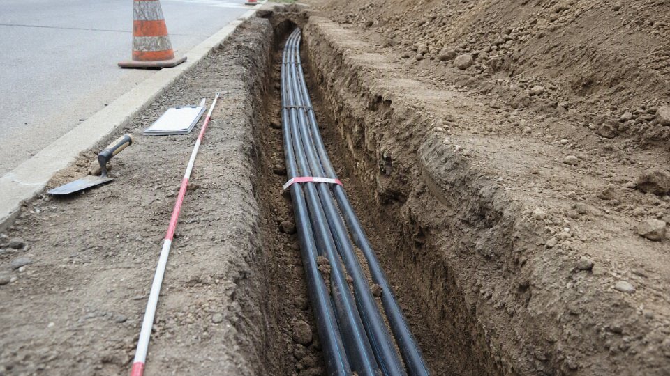
For procurement and project control, treat permits and inspections as part of the installation sequence, not paperwork to clean up later. A typical controlled sequence includes:
- Route layout approval before excavation, including utility locates and confirmation of known underground services.
- Material submittal review for cable type, voltage rating, wet-location or direct-burial suitability, conduit or duct material, warning tape, labels, and pulling accessories.
- Trench inspection before cable placement to verify depth, bedding, route clearance, water conditions, and absence of sharp debris.
- Inspection before backfill to confirm cable identification, spacing, mechanical protection, warning tape position, marker posts, and any required cable tiles or concrete cover.
- Grounding and bonding verification for metallic conduit, armor, cable screens, grounding conductors, and service equipment.
- Electrical testing and records, commonly including continuity, insulation resistance, phase identification, and project-specific test reports. Medium-voltage cables may require more formal acceptance testing under the applicable specification.
- As-built documentation showing route, depth where recorded, joints, ducts, spare conduits, pull boxes, markers, and deviations from the original drawing.
Cable identification is not decoration. Warning tape, tracer wire for nonmetallic ducts, surface markers, route posts, cable tiles, engraved labels in handholes, and durable circuit tags all reduce the chance that someone with a backhoe finds the circuit five years later by accident. In plant work, I prefer route markers that a maintenance technician can understand without opening a drawing set from a retired project engineer’s archive. That small detail saves time during outages.
Deeper is not automatically safer. Excessive depth can make fault repair slower, increase excavation hazards, complicate coordination with other buried services, and move the installation outside the assumptions used for ampacity and thermal calculations. Underground cable rating depends on load current, grouping, soil thermal resistivity, backfill, ambient ground temperature, burial depth, and duct arrangement. If a cable runs hotter because the installation differs from the design basis, the insulation ages faster even though the trench looks “extra protected.”
The practical boundary is simple: once the installation moves beyond a minor residential branch circuit, do not buy cable or dig trench based only on a remembered burial depth. Confirm the governing code edition, AHJ position, utility rules, site clearances, specified cable construction, and inspection hold points before procurement locks in the material. That is where underground wiring becomes an engineered installation rather than just cable in dirt.
Cable and conduit selection
The correct underground cable system is defined by duty, environment, installation method, and the standard the job must be accepted under—not by the phrase “underground wire.” For procurement, the safest specification names the conductor, insulation, screen or neutral, jacket, armor or conduit, voltage class, test standard, and installation assumptions, because each one changes service life, ampacity, termination practice, and inspection risk.
Start with the electrical duty
Electrical duty sets the cable family before soil or trench details are even useful. A small single-phase branch circuit, a three-phase feeder to a pump station, and a medium-voltage loop feeder may all be “buried,” but they do not belong in the same purchasing conversation.
Define at least these items before requesting pricing:
- Voltage class: Low-voltage building feeders, 600/1000 V industrial circuits, and medium-voltage systems use different insulation constructions, test voltages, accessories, and termination practices.
- Phase arrangement: Single-phase, three-phase three-wire, three-phase four-wire, concentric neutral, or separate protective earth affects core count, screen bonding, and trench layout.
- Load current and demand factor: Nameplate current alone can oversize or undersize a feeder. Continuous process loads, irrigation pumps, EV charging banks, and intermittent utility equipment behave differently.
- Starting current: Motors, compressors, and transformers can pull several times running current during starting or energization. That affects voltage drop, thermal cycling, and protection coordination.
- Fault level: Short-circuit withstand must be checked for both conductors and metallic screens or armor. A cable that carries load current comfortably may still fail thermally during a high fault if protection clearing time is long.
- Frequency and power quality: Standard 50 Hz or 60 Hz service is straightforward. Variable-frequency drives, harmonics, and long motor leads may require shielded cable, different grounding practice, or attention to insulation stress.
- Acceptable voltage drop: The cable is not just a current carrier; it is part of the process performance. A long buried run to a motor or remote panel can meet ampacity and still cause nuisance trips or weak starting if voltage drop is ignored.
In practice, I like to see both steady-state and starting voltage drop calculated before cable size is frozen. It is much cheaper to correct the cross-section on a purchase order than to explain later why a pump starts fine in cool weather and stalls during peak summer load.
Conductor material and size
Copper gives higher conductivity in a smaller cross-section, easier termination in cramped panels, and wide acceptance across industrial specifications. Aluminum gives lower weight and often better cost per ampere, but it needs larger cross-section, correct lugs, oxide control, torque discipline, and installers who do not treat it like copper.
| Selection point | Copper conductor | Aluminum conductor |
|---|---|---|
| Conductivity and size | Smaller for the same ampacity and voltage drop | Larger for the same duty |
| Weight | Heavier, especially painful on large reels | Lighter, easier on pulling and handling |
| Cost behavior | Usually higher material cost | Often lower, but depends on metal markets and freight |
| Terminations | Broad compatibility; still requires correct lugs | Requires Al-rated or dual-rated lugs, compound where specified, and proper torque |
| Corrosion concerns | Good general behavior, but not immune in aggressive environments | Sensitive to poor terminations and moisture ingress at joints |
| International acceptance | Common in conservative industrial and utility specs | Accepted in many markets, rejected or limited in some project standards |
The trade-off flips by project type. For a short critical feeder in a wet plant room with limited termination space, copper may be the cleaner engineering choice even if procurement dislikes the first price. For long site distribution, solar farms, utility laterals, or high-volume projects, aluminum can make commercial sense if the design accounts for voltage drop, larger conduit fill, pulling tension, and approved terminations.
Do not select conductor size from ampacity alone; check voltage drop, short-circuit withstand, installation derating, and termination temperature rating together. A 90°C insulated cable connected to 75°C-rated equipment, for example, may have to be sized using the lower termination limit depending on the applicable code and product listing.
Insulation system
The insulation system controls dielectric performance, thermal endurance, overload tolerance, flexibility, and water behavior. Underground service is unforgiving because moisture, heat, and mechanical stress stay with the cable for decades; you cannot “inspect” buried insulation the way you inspect a tray run.
Common options include:
- XLPE insulation: Widely used for low-voltage and medium-voltage power cables. It has strong dielectric properties, good thermal rating, and good overload behavior compared with ordinary PVC. It is less flexible than EPR in some constructions and demands proper termination workmanship, especially on shielded medium-voltage cables.
- EPR insulation: Often preferred where flexibility, moisture resistance, and cyclic loading matter. It is common in mining, utility, and industrial feeder applications. EPR can be easier to handle in cold conditions, though construction and manufacturer design matter.
- PVC insulation: Common in lower-voltage building and control cables. It is economical and familiar, but thermal rating, flexibility in cold weather, smoke performance, and long-term wet-service suitability must be checked against the actual product standard.
- Special compounds: Fire-resistant, low-smoke, halogen-free, oil-resistant, or high-temperature insulation systems may be required by tunnels, transit facilities, petrochemical plants, data centers, or local authority rules.
Any cable marked for outdoor use can be directly buried without conduit.False
Outdoor sunlight resistance, wet-location rating, and direct-burial suitability are separate requirements. The cable marking, applicable standard, and local authority acceptance must confirm the permitted installation method.
Jacket, sheath, and environmental protection
The outer sheath is the cable’s first defense against the trench. It sees wet soil, stones, pulling abrasion, hydrocarbons, fertilizer, termites in some regions, rodents near farms or substations, and chemical runoff that nobody mentioned during tendering.
Typical jacket and sheath choices:
- PVC: Economical, easy to process, and widely available. Flame-retardant PVC compounds are common, but ordinary PVC may be less suitable for severe chemicals, low-smoke requirements, or very cold handling.
- PE or HDPE: Good moisture resistance and abrasion resistance. Often used where buried durability matters, though flame performance is usually poorer than flame-retardant PVC unless specially compounded.
- LSZH compounds: Used where smoke and halogen acid gas are major concerns, such as tunnels, enclosed public areas, and certain infrastructure projects. They are not automatically the best direct-burial jacket; mechanical and water performance still need review.
- Oil-resistant compounds: Useful around refineries, fuel storage, workshops, and generator yards where hydrocarbons can attack ordinary sheaths.
- Termite-resistant or rodent-resistant constructions: Relevant in parts of Asia, Africa, Australia, agricultural sites, and utility corridors. Options may include special sheath additives, metallic barriers, armor, or conduit protection depending on local environmental rules.
- Chemical-resistant sheaths: Needed where soil contamination, wastewater treatment chemicals, saline ground, or industrial runoff may be present.
A simple soil report can change the cable construction. Clay with high moisture, crushed backfill, coastal salinity, and contaminated brownfield soil are not the same cable environment, even if the load current is identical.
Armor, conduit, and mechanical protection
Mechanical protection is justified when the cable may face impact, settlement, digging damage, crushing load, rodents, or installation abuse. It is not free protection: armor increases diameter, weight, bending stiffness, gland cost, and sometimes induced losses.
Common protection methods include:
- Steel wire armor: Strong mechanical protection for multicore low-voltage and control cables. It can also serve as a protective earth only where permitted and correctly sized by the applicable standard.
- Aluminum wire armor: Often used for single-core AC cables to avoid magnetic heating associated with ferromagnetic steel around individual phases.
- Steel tape armor: Good crush and impact resistance in some direct-burial constructions, but less flexible than wire armor and not ideal for every pulling route.
- Corrugated metallic sheath: Used in certain utility and industrial cable designs for moisture barrier and mechanical strength. Termination accessories and bonding practice must match the cable system.
- Nonmetallic conduit: PVC, HDPE, fiberglass, or similar ducts protect against soil contact and simplify replacement in some layouts. They also add thermal resistance and pulling constraints, which can reduce ampacity.
The mechanism is easy to underestimate: putting cable in duct reduces heat transfer from conductor to soil because air gaps, duct wall, and grouped ducts raise thermal resistance. You gain replaceability and mechanical protection, but you may sacrifice ampacity or need a larger conductor. This conclusion stops holding where the duct bank has engineered thermal backfill, controlled spacing, and verified loading assumptions.
Shielding, screens, bonding, and grounding
Medium-voltage underground cables are normally not just insulated conductors with jackets. They may include conductor screens, insulation screens, metallic screens, copper tape, copper wire screens, concentric neutrals, or metallic sheaths to control electric stress and provide a fault-current path.
For engineering and procurement, define:
- Screen construction and cross-section: It must handle charging current, earth-fault current, and protection clearing time.
- Bonding method: Single-point bonding, both-end bonding, or cross-bonding changes circulating current, sheath voltage, losses, and safety practice.
- Grounding continuity: Screens, armor, metallic conduit, glands, link boxes, and earth conductors must form a verified grounding system, not a collection of metal parts.
- Touch voltage: Long runs and high fault levels can produce dangerous sheath or armor voltages if bonding is wrong.
- Concentric neutral requirements: Common in some utility distribution systems, but not interchangeable with every IEC-style screened cable design.
For low-voltage circuits, grounding still matters. A buried feeder with a damaged protective earth, loose gland, or corroded joint may pass a casual visual check and fail when fault current needs a low-impedance return path.
Thermal design and derating
Ampacity tables are only a starting point. Underground cable temperature depends on conductor losses, insulation rating, soil thermal resistivity, depth, duct arrangement, grouping, seasonal ground temperature, and load profile.
Check these conditions before final sizing:
- Soil thermal resistivity: Dry sand, wet clay, native soil, and thermal backfill conduct heat differently. Drying around a hot cable can raise resistance further.
- Grouping and spacing: Multiple circuits in one trench heat each other. Tight duct banks need calculated derating, not guesswork.
- Duct fill and air gaps: A loosely filled conduit can run hotter than direct burial because heat must cross trapped air and duct material.
- Ambient and seasonal effects: Ground temperature, plant load, and solar gain at risers often peak together. I have seen riser sections near dark steel structures run much hotter than the buried span.
- Burial depth: Deeper burial can stabilize temperature but may reduce heat dissipation depending on soil and layout.
- Load profile: A cable feeding a steady 24/7 process load is not thermally equivalent to a short-duration irrigation or standby feeder.
Good specifications state the assumed installation condition. If no soil thermal resistivity is available, either test it or require the designer and supplier to state the assumption used; otherwise two bids may look equal while being sized on different thermal worlds.
Pulling and installation limits
A cable that is electrically correct can still be a bad purchase if it cannot be installed through the planned route. Reel diameter, bend radius, pulling tension, sidewall pressure, conduit fill, and lubricant compatibility all belong in the technical review.
Control the practical items:
- Minimum bend radius: Check both during pulling and final installed position. Armored and medium-voltage cables usually need more generous bends than small low-voltage conductors.
- Maximum pulling tension: Based on conductor material, pulling eye method, cable construction, and supplier limits. Aluminum conductors and long pulls need special attention.
- Sidewall pressure: Critical at bends. A pull may be under total tension limit but still damage cable at a sweep elbow.
- Conduit fill: Excess fill increases pulling force and heat. Use the applicable electrical code or project standard, not a “looks like it fits” judgment.
- Jam ratio: Three single-core cables in conduit can jam depending on cable outside diameter and conduit inside diameter. This is one of those avoidable field problems that ruins a weekend shutdown.
- Lubricant compatibility: Pulling compound must be compatible with the cable jacket and conduit material.
- Reel handling: Store reels upright, protect ends from water ingress, use proper jacks, and avoid dragging cable across gravel or rebar chairs.
Certification, tests, and traceability
For international procurement, compliance must be named. “IEC cable,” “UL cable,” or “BS cable” is not enough unless the exact standard, voltage class, construction, and test scope are clear.
Common documentation requirements include:
- Applicable IEC, BS, EN, UL, CSA, ICEA, AS/NZS, or local authority standards
- Project-specific data sheets and approved cable schedules
- Factory routine test reports
- Type test evidence where required
- Material certificates for conductor, insulation, sheath, armor, or special compounds
- Drum number, length, batch, and production traceability
- Marking requirements on cable sheath and packaging
- Installation manual or handling limits for bend radius, pulling tension, and storage
Routine tests confirm that the manufactured cable passed required production checks. Type tests demonstrate that a cable design has been validated against a standard. They are not the same thing, and procurement should not accept one as a substitute for the other without engineering approval.
Procurement risk in bulk underground cable orders
Bulk buyers get into trouble when they request only “underground cable,” “direct burial wire,” or a size and voltage rating. That leaves too many decisions to the supplier’s default construction, which may not match the soil, duct system, local inspection practice, termination accessories, or operating duty.
A defensible purchasing specification should state:
- Conductor material, class, and cross-section or AWG/kcmil size
- Number of cores or single-core arrangement
- Rated voltage and system grounding condition
- Insulation material and temperature rating
- Screen, concentric neutral, sheath, or armor details where applicable
- Jacket material and special resistance requirements
- Direct burial, duct, tray-to-burial transition, or riser installation method
- Required standards and certification documents
- Length tolerance, drum size, packing method, and marking
- Approved accessories or termination compatibility
- Design assumptions for ampacity, soil, grouping, and ambient conditions
A complete construction specification is not paperwork for its own sake; it is how the buyer prevents a cheap cable from becoming an expensive trench problem. For large international projects, the commercial comparison should be made after the technical construction is normalized. Otherwise the lowest bid may simply be the cable with omitted armor, lighter screen, unsuitable sheath, undocumented wet-location rating, or assumptions that do not survive site inspection.
Trench and bedding design
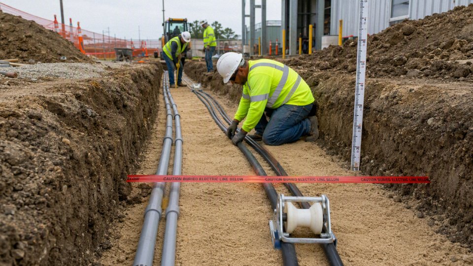
A buried cable usually fails early because of water, heat, movement, or mechanical damage around it, not because the catalog sheet was poorly written. A good trench gives the cable a stable, drain-aware, thermally predictable path with no sharp bearing points and enough access for pulling, inspection, and future repair. Treat the trench as part of the electrical system, not as low-value civil work.
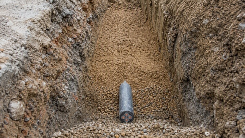
Route planning
The best underground route is usually the one that is boring on paper: straight runs, controlled bends, few crossings, and no surprises under future roads, slabs, tanks, or landscape work. I get nervous when a route looks “clever” because clever often means extra bends, buried joints, undocumented offsets, or a crossing under something nobody wants to dig up later.
Good route planning should check:
- Straightness and pullability: Keep runs as straight as practical. Every bend adds pulling tension, sidewall pressure, and installation risk, especially with large conductors or multi-core armored cable.
- Accessible future excavation: Avoid routing under permanent structures, heavy foundations, loading docks, drainage channels, and production equipment unless there is no better option.
- Drainage behavior: Do not use the trench as a watercourse. Low points, clay pockets, and road-edge washouts can keep cables or conduits submerged and can destabilize bedding.
- Utility crossings: Minimize crossings with gas, water, sewer, communications, fire mains, steam, and process drains. Where crossings are unavoidable, keep safe separation and use protection methods required by the local authority and utility owner.
- Controlled bends: Use long sweep bends rather than tight elbows. The required radius depends on cable construction and supplier limits; armored and medium-voltage cables are far less forgiving than small building wire in conduit.
- Separation from heat sources: Keep away from steam lines, hot condensate drains, buried process piping, and sun-heated surface structures where possible. Heat is an ampacity problem, not just a comfort issue.
A representative plant case: a feeder routed along the edge of a paved yard may look convenient, but if forklifts later crack the pavement and water drains into the trench line every winter, the installation becomes a maintenance liability. The better route may be three meters longer but on higher ground with fewer crossings and easier access.
Excavation safety
No trench should be opened until underground services have been located and the work boundary is controlled. Drawings are useful, but they are not proof. Old plants have abandoned conduits, undocumented repairs, and “temporary” lines that became permanent years ago.
Before digging, the site team should confirm:
- Permit-to-dig approval with current drawings, isolation requirements, and responsible sign-off.
- Utility locating using the required local one-call process, site records, cable avoidance tools, ground-penetrating methods where justified, and hand digging near known services.
- Shoring, benching, or sloping where trench depth, soil type, weather, and worker access require it. This is not a judgment call for the electrician in the trench; follow the applicable excavation safety rules.
- Confined-space review for deep pits, manholes, vaults, pull boxes, and areas where gases can collect.
- Traffic control for road crossings, plant yards, forklift routes, and public areas.
- Weather planning so the trench is not left open through heavy rain, freezing conditions, or a weekend with no dewatering plan.
Wet clay in March and dry granular fill in August do not behave the same way. A trench that was safe in the morning can slump after rain, vibration, or a water main leak nearby.
Trench dimensions
Trench dimensions are driven by burial depth, installation method, cable size, conduit spacing, pulling access, and the civil tolerance the crew can actually hold. Residential branch circuits may involve relatively shallow trenches under certain approved wiring methods, while industrial duct banks and direct-buried feeders often need much more room for bedding, separation, warning layers, and compaction.
Dimensioning should allow for:
- Required cover depth: Measure from finished grade, not from today’s rough excavation level. Landscaping, paving, grading, or later resurfacing can change cover.
- Working width: The trench must be wide enough to place bedding evenly around the cable or conduit, not just drop it into a slot.
- Side clearance: Keep cable or conduit away from trench walls, stones, roots, rebar, and broken concrete.
- Spacing between conduits or cables: Closely grouped circuits run hotter and may need ampacity derating or engineered backfill.
- Bend sweep radius: Pull points, sweeps, and risers need physical room. A trench that is too narrow often forces the crew into tighter bends than the cable manufacturer permits.
- Workspace at pull points: Leave enough room around handholes, junction boxes, duct bank turns, and risers for pulling equipment and inspection.
The trade-off is cost versus installability. Narrow trenching saves excavation and reinstatement cost, but it can increase pulling force, damage risk, and heat buildup. For a small garden circuit, that trade may be acceptable within code. For a production feeder that shuts down a line if it fails, cheap trench geometry is usually false economy.
Bedding and backfill materials
Bedding is there to support the cable or conduit uniformly, prevent point loading, and create predictable thermal and moisture behavior. It should not be whatever the excavator happened to pull out of the ground.
Common bedding and backfill choices include:
| Material | Where it fits | Watchpoints |
|---|---|---|
| Sand | Common around small direct-buried cables and conduits where local practice allows | Can dry out and lose thermal performance; may wash away if drainage is poor |
| Screened native soil | Useful when clean, fine, stable, and compatible with the cable jacket or conduit | Reject material with stones, glass, scrap metal, ash, slag, roots, or corrosive content |
| Fine thermal backfill | Better for feeders where ampacity depends on soil heat transfer | Must be installed at the specified moisture and compaction condition |
| Controlled low-strength material | Useful for duct banks, road crossings, and stable encasement | Harder future excavation; verify heat transfer, not just strength |
| Engineered thermal backfill | Used for high-load circuits, duct banks, or poor native soils | Needs design input; do not substitute ordinary sand because it “looks close” |
The mechanism is simple but often ignored: conductor losses produce heat, heat must move through insulation, jacket, conduit or armor, bedding, and soil, and each layer adds thermal resistance. Dry, loose, or poorly compacted backfill traps heat. Multiple loaded circuits in the same trench warm each other, so a cable that looks adequate in free air or a single-circuit calculation may run too hot underground.
Backfill quality and compaction
Backfill damage is one of the most preventable causes of buried cable trouble. The cable may pass megger testing on day one, then fail after years of jacket abrasion, crushed conduit, water tracking, or thermal cycling.
Reject or control these materials and conditions:
- Rocks and sharp aggregate that can point-load jackets, deform conduit, or damage protective sheaths.
- Construction debris such as brick, concrete chunks, metal offcuts, tie wire, glass, and scrap packaging.
- Frozen soil that later thaws and settles unevenly.
- Corrosive fill including ash, contaminated soil, chemical waste, slag, or highly aggressive industrial residues.
- Excessive compaction loads directly over cable or plastic conduit before enough cover has been placed.
- Standing water that softens support, carries fines away, or turns a trench into a drain.
Compaction matters, but so does how it is done. A jumping jack or plate compactor used too early can ovalize ducts, crack weak conduit joints, or squeeze cable against stones. Build cover in lifts, use suitable material around the cable zone, and let the civil specification say what density is required above the protective layer.
Drainage, thermal performance, and physical protection
Underground electrical systems should be specified for wet-location service where applicable; they should not depend on the trench staying dry.
A buried cable route should still be designed to avoid long-term pooling and washout even when the cable is wet-location rated.True
Wet-location suitability addresses electrical insulation performance in moisture, but it does not eliminate soil instability, erosion, corrosion exposure, duct settlement, or maintenance-access problems caused by poor drainage.
That distinction matters on sites with seasonal groundwater, irrigation, snowmelt, or paved areas that shed water into cable routes.
Thermal and drainage behavior are connected. Saturated soil can sometimes conduct heat better than dry loose soil, but washout, voids, and unstable bedding are bad for mechanical support. Very dry compacted soil, duct banks with many loaded circuits, and poor thermal backfill can raise conductor operating temperature and force ampacity derating. The boundary is important: if load is low and cable spacing is generous, ordinary clean backfill may be adequate; once circuits are heavily loaded, grouped, or installed in poor soil, thermal resistivity needs engineering review rather than guesswork.
Physical protection should be placed where a future excavator will actually encounter it before hitting the cable:
- Warning tape above the cable or duct zone, at the locally required depth.
- Cable tiles, boards, or protective covers over direct-buried cables where required or prudent.
- Concrete slabs or encasement at road crossings, shallow-risk zones, and high-damage areas, subject to thermal review.
- Marker posts or route markers at changes in direction, crossings, and long rural or industrial runs.
- Bollards and riser guards where conduits or cables emerge from grade near vehicles, pallets, mowers, or maintenance traffic.
The above-ground transition is a common weak point. A perfect trench does not help much if the riser is exposed to forklift forks, UV-damaged plastic, a loose coupling, or water running down an unsealed wall penetration.
Installation steps that matter
- Hold a pre-installation verification meeting before anyone opens a drum.
The most expensive underground cable failures I have seen usually started as paperwork mistakes: the right trench with the wrong cable, the right cable pulled into the wrong duct, or an unapproved route change made because a machine foundation was in the way. Before installation, the supervisor should confirm:
- Latest approved drawings, route layout, trench sections, and equipment termination details
- Cable schedule against drum labels, voltage rating, conductor size, core count, armor or shield type, and jacket material
- Factory certificates, test reports, wet-location suitability, and any project-specific approvals
- Permit status, inspection hold points, utility locating, and excavation clearance
- Drum condition, flange damage, visible jacket damage, and correct storage history
- Pulling equipment rating, reel stands, rollers, winch calibration, lubricant, mandrels, duct brushes, and test instruments
- Crew briefing on bend radius, pulling direction, communication signals, emergency stop, and who has authority to reject a pull
Do not treat cable installation as a labor task after procurement is complete; it is the point where design assumptions become physical risk. A 500 m cable run that looks correct on a bill of materials can still fail if the crew pulls from the wrong end, skips a pull box, or lets the drum roll across crushed stone.
- Install conduit or duct as if you will personally have to pull the cable through it later.
Conduit alignment controls pulling force, jacket wear, and future replaceability. For PVC or HDPE duct banks, joints need to be clean, fully seated, and made by the correct method: solvent-welded joints for compatible rigid PVC systems, fusion or approved mechanical couplers for PE systems, and manufacturer-approved transition fittings where materials change. A sloppy joint lip inside a duct is enough to shave a cable jacket under tension.Use long sweep elbows rather than tight plumbing-style bends. Pull boxes or handholes should be placed where total bend angle, route length, or equipment access would otherwise make a pull risky. There is a trade-off here: fewer boxes reduce civil cost and water-entry points, but they raise pulling tension and make future replacement harder. That choice flips on long runs, large conductors, armored cables, or routes with multiple bends.
Where drainage is part of the design, slope the conduit so water does not sit at equipment entries. In practice, underground conduits often contain moisture no matter how carefully they are sealed, so the cable still needs wet-location suitability. Before pulling cable, mandrel test the duct, brush or swab it clean, remove stones and dried mud, and cap or seal unused ends. Spare conduits are cheap while the trench is open and painful after the yard is paved.

Handle drums like finished electrical equipment, not construction material.
Store cable drums upright on firm ground, chocked, and protected from standing water. Lift with a shaft through the drum or approved lifting beam; do not choke the cable with chains or forklift tines. Roll drums only in the marked direction so the cable does not loosen on the reel. If the manufacturer gives a minimum installation temperature, follow it, especially for PVC-jacketed cable in cold weather. A jacket that flexes cleanly at 20°C may crack or stress-whiten on a cold morning.Keep the cable off mud, rebar, sharp trench plates, and broken concrete. Jacket cuts made during handling are easy to miss because the conductor still tests fine before energization. The problem appears months later after moisture migrates through the damage, or after a shield fault starts tracking along a contaminated surface near a termination.
Control the pull, do not just complete it.
Pulling tension should be calculated before the pull using cable weight, route length, bends, friction estimate, and the manufacturer’s allowable tension. The allowable value depends on conductor material, pulling eye attachment, armor, and cable construction; do not assume one rule fits every cable. Compatible pulling lubricant reduces friction, but it must be suitable for the cable jacket and conduit material.During the pull:
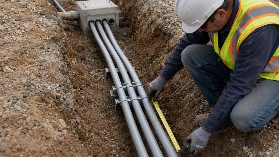
- Use pulling eyes, basket grips, swivels, and grips exactly as intended
- Keep cable rollers positioned so the jacket never drags across trench edges or duct mouths
- Control winch speed; steady and moderate is better than jerky movement
- Watch sidewall pressure at bends, not only straight-line pulling tension
- Stop if the cable surges, rotates excessively, bird-cages, or suddenly requires much higher force
Keep radio or hand-signal communication between feed end, pull end, and intermediate points
The mechanism is simple but unforgiving: tension stretches the cable along its length, while sidewall pressure crushes it against the outside of a bend. A pull can be under the maximum tension limit and still damage insulation or deform shielding at an elbow. This is why long sweeps, clean ducts, and correct roller placement matter more than a stronger winch.
For direct burial, place the cable; do not drag it into position.
Direct-burial cable should sit on prepared bedding without kinks, twists, or point loads. Maintain the specified separation from other power circuits, communications cables, metallic services, gas lines, water lines, and heat sources. At crossings, use protective sleeves, tiles, slabs, or conduit sections where required by the design or authority having jurisdiction.Watch for small, ugly details:
- Stones pressed against the jacket during compaction
- Cable crossing over a hard duct edge
- Rebar chairs, scrap wire, or broken brick left in the trench
- Bends tightened by workers trying to “make it fit”
Warning tape placed too low, too high, or missing at changes in route
Warning tape should be above the cable at the specified depth so the next excavator hits the tape before reaching the electrical system. Photograph the cable position, crossings, and risers before backfill. A few clear photos with a tape measure in frame can save hours of fault locating later.
Minimize buried splices, and make unavoidable joints traceable.
Every buried splice is a future maintenance question. Where possible, order the cable in lengths that avoid underground joints, or locate joints in accessible handholes. If a buried joint is unavoidable, use a listed or certified underground joint kit suitable for the cable voltage, insulation type, conductor material, shield or armor arrangement, and soil moisture exposure.Good jointing practice includes:
- Clean, dry preparation of insulation and semiconductive screens where applicable
- Correct connector crimping tools and dies
- Shield continuity and bonding carried through the joint
- Moisture sealing exactly as specified by the kit manufacturer
- Mechanical protection so the joint is not bent or loaded during backfill
Permanent route records so the joint can be found later
Heat-shrink, cold-shrink, resin, gel, and molded joint systems each have their place. The right choice depends on voltage class, installer skill, ambient temperature, water exposure, and whether the joint may need future inspection. A joint that is electrically acceptable on the test bench can still fail early if installed with wet gloves in a muddy trench.
Treat terminations and risers as high-risk transition points.
The change from underground cable to switchgear, panelboards, motors, lighting poles, or outdoor enclosures concentrates mechanical, moisture, UV, and grounding risks. Use the correct glands, bushings, bonding jumpers, sealing fittings, and strain relief. Where cables rise out of grade, protect them with rigid conduit, guards, or bollards if vehicle or forklift contact is possible.Check for:
- UV-resistant exposed jacket or proper sleeving
- Smooth bushings at conduit exits
- Correct armor bonding or shield grounding method
- Drip loops or sealing arrangements that prevent water tracking into equipment
- Phase identification before cutting to final length
- Enough slack for termination without violating bend radius
Backfill in controlled lifts and keep proof of what was buried.
Initial backfill should protect the cable or conduit before heavy compaction starts. Use specified sand, screened soil, or thermal backfill where required; do not allow excavated rock to be pushed directly onto the cable. Compact in lifts suited to the civil specification, but keep compactors away from unprotected cable positions until adequate cover exists.Record depth, route, offsets from fixed structures, joint locations, crossings, spare ducts, and warning tape position before closing the trench. GPS helps, but do not rely on it alone around steel structures or tight industrial yards. Dimensioned sketches and photos tied to manholes, building corners, or equipment pads are still valuable.
Keep the circuit de-energized until testing and inspection are complete.
Energization should wait for required inspections, insulation resistance testing, continuity checks, grounding and bonding verification, shield tests where applicable, and phase identification. For medium-voltage or project-critical cables, the test method and voltage level should come from the project specification, cable manufacturer, and applicable standard, not from habit.This sequence assumes the design, cable type, burial depth, and authority approvals have already been settled. If the installation crew discovers route changes, unexpected groundwater, damaged duct, undocumented utilities, or cable defects, the correct response is to stop and revalidate the installation plan before the trench gets closed and the defect becomes expensive to find.
Testing and documentation
Do not treat testing as a formality after the trench is already covered. The last practical chance to prove an underground wiring system is safe, compliant, and maintainable is before backfill hides the cable, joints, bedding, and route. Once the soil is compacted, every missing photo, unmarked splice, or unrecorded depth becomes a future excavation risk.
Pre-backfill inspection
Before anyone calls for sand cover, warning tape, or final backfill, walk the route with the installer, inspector, and site representative if possible. I prefer doing this with marked-up drawings in one hand and a phone or tablet camera in the other; memory is not good enough six months later when a drainage contractor wants to cut across the same area.
Record and verify:
- Trench depth at representative points and at any changes in grade.
- Bedding material, thickness, and absence of sharp rock, scrap rebar, broken block, or construction debris.
- Actual cable or conduit route, including offsets from walls, curbs, fence lines, foundations, pits, and road edges.
- Cable jacket condition, looking for cuts, crushed areas, kinks, abrasion, or flattening from mishandled pulling.
- Separation from water, gas, telecom, steam, drainage, and other electrical services.
- Conduit condition, including bell mouths, couplings, sweeps, seals, spare ducts, and pull-box entries.
- Warning tape or marker board location above the cable, not sitting directly on it.
- Visible joint quality: clean joint bodies, correct support, no sharp bending into the joint, no standing water, and no obvious resin or heat-shrink defects.
For direct-burial cable, the inspection is more than housekeeping. Soil pressure, stones, and thermal conditions act directly on the cable sheath; a small jacket cut that looks harmless in dry weather can become the starting point for moisture tracking after one wet season. For conduit systems, the weak points are often crushed ducts, poor sweeps, and bad terminations that make future cable replacement almost impossible.
Electrical tests before energizing
The electrical test set should match the cable voltage class, insulation type, project specification, and applicable code or utility requirement. A small residential feeder and a medium-voltage industrial supply do not need the same commissioning package, but both need a written record that proves the conductors are correctly identified and fit to energize.
Typical low-voltage checks include:
- Continuity testing for every conductor, including spares.
- Conductor identification from source to load, with labels matching drawings and panel schedules.
- Insulation resistance testing between conductors and to ground, using test voltage and minimum values from the project specification, cable manufacturer, or governing standard.
- Grounding and bonding continuity, including metallic conduit, armor, earth conductors, and equipment grounding paths.
- Phase rotation checks for three-phase loads before motors, pumps, compressors, or HVAC equipment are released for operation.
- RCD or GFCI function testing where required, using the correct test method rather than only pressing the front-panel button.
Where sheath testing is applicable, especially on certain armored, shielded, or medium-voltage cable systems, test the outer serving or sheath integrity before backfill and again after civil work if the specification calls for it. This catches damage from pulling, rollers, backfill equipment, or careless shovel work around risers.
Medium-voltage commissioning
Medium-voltage underground cable deserves a formal commissioning plan, not a few improvised megger readings at the end of the job. Depending on the cable design and project acceptance criteria, the test package may include:
- VLF withstand testing.
- Tan delta testing to assess dielectric condition.
- Partial discharge testing where specified by the engineer, utility, or owner.
- Cable sheath integrity testing.
- Phasing checks, grounding checks, and link-box verification.
- Review against manufacturer limits and project acceptance criteria.
The trade-off is straightforward: more diagnostic testing costs time and specialist labor, but it can expose installation damage before a feeder failure shuts down production. The preferred level of testing usually flips when the circuit supplies critical production, fire pumps, data infrastructure, process cooling, or any load where outage cost is far higher than the test cost. This logic stops holding if the selected test method is not suitable for the cable type or termination system, so the test voltage, duration, and pass criteria must come from the current standard, utility requirement, manufacturer guidance, or project specification.
Thermal and load verification
Testing should not only ask, “Is the cable electrically sound today?” It also has to ask, “Will it run within its design temperature for the next ten or twenty years?”
Compare the installed condition against the ampacity calculation and load schedule:
- Actual burial depth versus the design assumption.
- Number of loaded circuits in the trench or duct bank.
- Spacing between cables or conduits.
- Soil thermal resistivity assumed in the calculation versus known site conditions.
- Nearby heat sources, including steam lines, process drains, sun-exposed risers, and heavily loaded adjacent feeders.
- Expected operating current, duty cycle, harmonic content, and future load growth.
- Derating applied for grouping, ambient temperature, duct fill, and installation method.
This is where procurement and construction sometimes collide. A cable that looked correctly sized on a purchase order may be marginal after the contractor groups extra circuits in the same trench or changes from open burial to a tight duct bank. The mechanism is simple: poorer heat dissipation raises conductor temperature, which accelerates insulation aging and reduces available ampacity.
As-built records and maintenance planning
As-built documentation is not paperwork for the archive box; it is how the next electrician avoids cutting into a live feeder. A usable closeout package should include:
- Final route drawings with clear reference points.
- GPS coordinates where useful, especially on large sites, solar farms, utilities, yards, and remote industrial areas.
- Burial depth records at representative points and crossings.
- Cable type, size, voltage rating, construction, and drum numbers.
- Test certificates with date, instrument details, test values, weather conditions where relevant, and technician signoff.
- Joint, splice, pull-box, manhole, riser, and termination locations.
- Photos before backfill, taken wide enough to show fixed landmarks.
- Inspection signoffs from the authority, utility, owner, or engineer as required.
Maintenance planning starts at handover. Set inspection intervals for terminations, above-ground risers, kiosks, manholes, link boxes, glands, seals, and bonding points. Track load growth against the original design current, keep insulation resistance or tan delta trends where that level of testing is justified, and put the route into the site excavation permit system. A buried cable is only “fit and forget” until someone installs a fence post, drainage trench, or new machine foundation through it.
Common underground wiring failures
Most buried cable failures come from a short list of causes: water entry, mechanical abuse, overheating, chemical exposure, poor bonding, and skipped installation controls. In practice, the highest-risk points are often not the straight cable run, but the transitions, joints, handholes, risers, and terminations where materials and workmanship change. That is where procurement specs and site supervision need to be just as strict as they are for the cable itself.
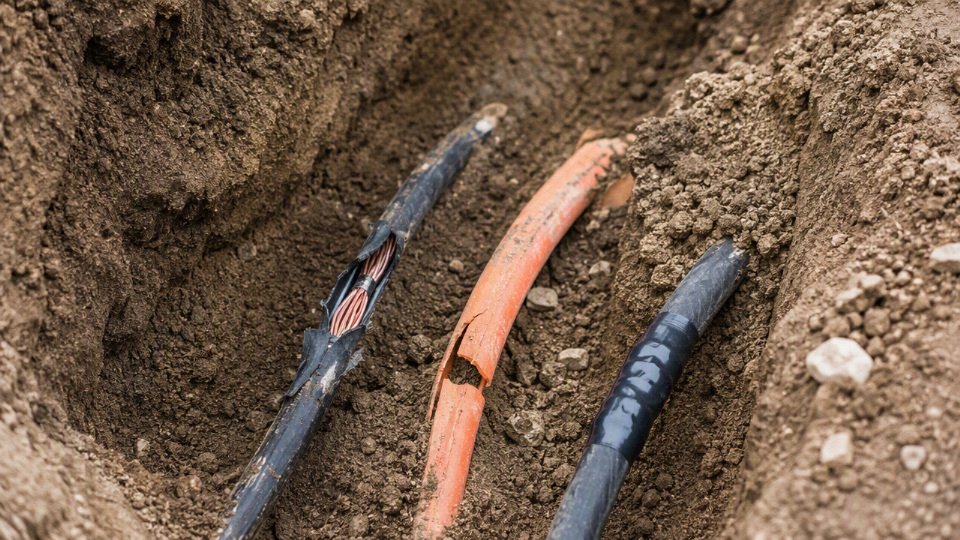
Moisture ingress
Water does not need a dramatic flood to damage underground wiring. A nicked jacket, a poorly sealed splice, an open conduit end, or a handhole that sits below the seasonal water table can let moisture track along the cable assembly. In medium-voltage XLPE systems, long-term moisture and electrical stress can contribute to water treeing, where microscopic water-filled paths grow through the insulation and reduce dielectric strength. Low-voltage circuits are less often discussed in those terms, but they still suffer from corrosion, ground faults, and insulation deterioration.
Common moisture paths include:
- Failed joints or heat-shrink kits installed on dirty, wet, or badly prepared cable ends.
- Damaged outer jackets from pulling, stones, or careless knife work.
- Unsealed conduits that collect runoff and behave like buried drainpipes.
- Condensation inside conduit caused by temperature swings between equipment rooms and outside soil.
- Flooded pull boxes, handholes, and vaults with no drainage path.
- Capillary water movement along strands, shields, armor interstices, or bedding material.
A conduit system is not automatically dry just because it is enclosed. Many underground conduits eventually contain water, so the conductors or cables inside still need to be rated for wet locations under the applicable code and project specification.
Mechanical damage
Mechanical failure is the one I see underestimated most often because the cable looks tough on the reel. Underground service is less forgiving. A small jacket cut can become a moisture entry point; a crushed duct can prevent cable replacement; a kink from pulling around a tight bend can weaken insulation before the circuit ever carries load.
The usual sources are:
- Excavator, post-hole auger, trenching, or landscaping strikes after the route is forgotten.
- Sharp stones or demolition debris used as backfill instead of screened bedding.
- Over-compaction directly above cable or conduit, especially with aggressive trench compactors.
- Conduit collapse from insufficient burial protection, poor material selection, or heavy traffic loads.
- Weak riser protection where cable emerges near walls, poles, pumps, gates, or loading areas.
- Pulling damage from excessive pulling tension, sidewall pressure, poor lubrication, or too many bends.
Warning tape and route markers do not stop every strike, but they reduce the chance that the first sign of the cable is a flash, trip, or dead production line.
Thermal overload
Underground cable ampacity depends on more than conductor size. Heat must move from the conductor through insulation, jacket, bedding, and soil. If the soil is dry, rocky, compacted differently than assumed, or crowded with other heat-producing circuits, the cable may run hotter than the design calculation expected.
Typical thermal overload causes include:
| Cause | What happens in service |
|---|---|
| Undersized conductors | Normal load pushes insulation temperature too high, shortening life. |
| Poor soil thermal resistivity | Heat cannot escape efficiently, especially in dry seasons or backfilled trenches. |
| Excessive duct fill | Air gaps and crowded conductors increase thermal resistance and pulling stress. |
| Harmonic heating | Nonlinear loads add neutral and conductor heating not captured by a simple current check. |
| Load growth | A cable sized for the original equipment quietly becomes undersized after expansions. |
| Derating errors | Grouping, ambient temperature, burial arrangement, or conduit effects are missed. |
The trade-off is familiar: upsizing conductors, spacing ducts, or using engineered thermal backfill costs more at installation, but it can avoid nuisance trips, premature insulation aging, and expensive civil rework later. That conclusion stops holding if the load is genuinely small, intermittent, and locked down by design; then the money may be better spent on protection, marking, and documentation.
Chemical and biological attack
Soil is not just dirt. Around factories, farms, roads, fuel systems, wastewater lines, and coastal sites, buried cable may face chemicals that standard assumptions do not cover. Hydrocarbons can attack some polymer jackets. Acids, alkalis, salts, fertilizers, and industrial effluent can accelerate corrosion of metallic armor, screens, conduits, and grounding paths. Incompatible backfill can also be a problem if slag, ash, contaminated fill, or chemically aggressive material is used because it was available on site.
Biological attack is site-dependent but worth specifying against in the right locations:
- Termites and insects in warm regions.
- Rodents near farms, food plants, and waste handling areas.
- Microbial activity contributing to corrosion of buried metallic components.
- Root intrusion into weak joints, ducts, or handholes.
For industrial direct-burial power cables, XLPE or EPR insulation with PVC, PE, LSZH, or armored protective constructions may be selected depending on moisture, impact, fire, chemical, and soil conditions. The supplier still needs the actual exposure conditions; no jacket material should be treated as universally resistant.
Grounding and bonding defects
Grounding problems can make an underground installation dangerous even when the phase conductors test acceptably. Floating shields, discontinuous armor, corroded metallic conduit, or loose bonding jumpers can leave exposed parts at an unsafe touch voltage during a fault. Incorrect neutral-ground arrangements are another serious issue, especially where feeders serve outbuildings, equipment skids, site lighting, or separately derived systems.
Look closely at:
- Shield bonding method and whether single-point or multi-point bonding was actually intended.
- Earth continuity across joints, pull boxes, metallic risers, glands, and terminations.
- Corrosion protection on buried metallic paths.
- Grounding electrode conductor routing and protection.
- Neutral isolation where required by the applicable code and system design.
These details belong on drawings and inspection records, not just in the electrician’s memory.
Installation shortcuts
Shortcuts underground are expensive because the defect gets buried. The most common ones are simple and preventable:
- Indoor-rated cable installed outdoors or underground.
- Unlisted or improvised splices wrapped and buried.
- Missing warning tape, marker posts, or route tags.
- Route changes made in the field but never recorded.
- Bends tighter than the cable or conduit minimum bend radius.
- Energizing before insulation resistance, continuity, phasing, and documentation checks are complete.
Symptoms requiring investigation
Investigate underground wiring when any of these appear:
- Nuisance breaker or RCD/GFCI tripping.
- Low or declining insulation resistance.
- Excessive voltage drop under load.
- Localized heating at risers, terminations, panels, or pull points.
- Recurring fuse operation without a clear load-side fault.
- Visible riser damage from vehicles, mowers, forklifts, or UV exposure.
- Water inside panels, junction boxes, handholes, or conduit ends.
- Unexplained corrosion on glands, armor, shields, ground bars, or metallic conduit.
A single symptom may be harmless, but repeated symptoms usually mean the buried system is giving early warning. The repair bill is almost always lower before the fault becomes a burned joint, a flooded enclosure, or a trench that has to be reopened under production pressure.
Frequently asked questions
Can I bury electrical wire without conduit?
Yes, but only if the cable is specifically rated and marked for direct burial, and the installation still has to satisfy the local electrical code. A normal indoor cable or building wire pulled straight into soil is not acceptable; moisture, soil chemistry, insects, rocks, and shovel damage will find weak points faster than most owners expect.
Even with direct-burial cable, conduit or extra mechanical protection may still be required where the cable:
- Rises out of the ground into a panel, pedestal, pole, or machine base
- Passes under a driveway, loading area, or forklift route
- Enters a building or foundation sleeve
- Runs through rocky backfill or disturbed industrial ground
- Is located where future excavation is likely
Direct-burial cable can always be installed without conduit for the full route.False
Direct-burial rating only addresses the cable's suitability for soil exposure. Code rules, mechanical damage risk, burial depth, and entry/exit protection may still require conduit or another protective method.
What type of wire is best underground?
The best underground wiring method depends on route risk and how painful future repair would be. For a simple residential feeder across clean soil, a listed direct-burial cable may be practical; for an industrial plant, wet-location conductors in conduit, armored cable, or a duct bank is usually easier to defend from a reliability and maintenance standpoint.
A useful way to compare the options:
| Underground wiring option | Where it fits best | Main advantage | Main limitation |
|---|---|---|---|
| Direct-burial cable | Low-risk routes with limited mechanical exposure | Fewer materials and faster installation | Harder to replace; vulnerable if bedding and warning tape are poor |
| Wet-location conductors in conduit | Branch circuits, feeders, equipment runs, sites needing future pull-out | Better mechanical protection and maintainability | Conduit joints, pulling tension, and water management still matter |
| Armored industrial cable | Plants, utilities, mines, chemical areas, exposed transitions | Stronger resistance to impact and crushing | Higher material cost, larger bend radius, termination skill required |
| Duct bank system | Critical feeders, medium-voltage routes, multi-circuit corridors | Organized, inspectable, expandable route | Higher civil cost and more coordination before pouring or backfill |
For industrial direct-burial power cables, insulation and jacket choices such as XLPE, EPR, PVC, PE, LSZH, and armored constructions should be selected around voltage, wet exposure, soil condition, impact risk, flame/smoke requirements, and the project standard being followed.
How deep should electrical wire be buried?
Burial depth is not a number to guess from a chart online. It depends on the wiring method, circuit voltage, overcurrent/GFCI protection, location, cover material, and the electrical code adopted by the local authority.
As a rough orientation, residential low-voltage branch-circuit burial depths often fall somewhere around 6 in to 24 in, depending on the method and protection used. That range is not a design instruction. Before trenching, verify:
- The applicable NEC, IEC, BS, AS/NZS, or local authority rule
- Whether the route is residential, commercial, agricultural, or industrial
- Whether the cable is direct burial, in PVC conduit, rigid metal conduit, or concrete-encased duct
- Whether vehicles, paving, landscaping, or future grading will change cover depth
- Inspection timing before backfill
On jobs I have seen go wrong, the trench was not “a little shallow”; the grade changed after landscaping or paving, and a once-compliant cover depth disappeared.
Is PVC conduit waterproof underground?
No underground conduit system should be treated as dry. PVC conduit can reduce mechanical damage and create a replaceable pathway, but groundwater, condensation, joint leakage, and temperature cycling can leave water standing inside the raceway.
That is why underground conductors in conduit normally need to be rated for wet locations. The practical design concern is not only insulation survival; water also affects pulling lubricant residue, corrosion at fittings, freeze expansion in cold climates, and termination boxes that were not drained or sealed properly.
Should underground cable be copper or aluminum?
Both copper and aluminum can work underground when the conductor is correctly sized, protected, and terminated. Copper carries more current for a given size and is more forgiving at terminations; aluminum is lighter and often lower cost on large feeders, but needs compatible lugs, oxide-inhibiting practices where required, and careful torque control.
The decision usually flips with feeder length and project scale. For a short, labor-sensitive branch circuit, copper may be the cleaner choice. For long, high-current feeders, aluminum can make commercial sense if voltage drop, conduit fill, pulling tension, short-circuit rating, and termination hardware are engineered together.
Can I splice underground electrical cable?
Avoid buried splices where practical. Every splice is a future failure point, especially in wet soil, flooded handholes, or routes that see settlement and thermal cycling.
If a splice is unavoidable, use an approved underground-rated splice kit matched to the cable type, voltage, conductor material, insulation system, and environment. Do not bury a general-purpose junction or improvised tape build-up and hope the backfill protects it. Record the splice location on the as-built drawing, measure from fixed landmarks, and photograph it before cover. The technician who has to find it five years later may be you.
What is the safest choice for an industrial site?
For industrial sites, the safest choice is usually an engineered system: cable in conduit, armored cable, or a duct bank selected around load criticality, mechanical exposure, soil condition, and maintenance strategy. A cheap direct-burial route across a yard can become expensive if it feeds a process line, fire pump, compressor, crane, or export-critical production area.
Specify the system against:
- Full-load current and starting current
- Voltage drop over the actual route length
- Short-circuit withstand and protective device clearing time
- Soil thermal resistivity and grouping with other circuits
- Chemical exposure, oil contamination, groundwater, and corrosion
- Vehicle traffic, excavation risk, vibration, and settlement
- Repair access, spare ducts, and shutdown windows
When should a cable manufacturer be involved?
Bring the cable manufacturer in early when the run is long, high-current, medium-voltage, export-controlled, chemically exposed, mechanically risky, or being purchased in bulk. Waiting until after the civil route is fixed can leave you with a cable that technically meets a catalog description but is difficult to pull, oversized for the duct, weak against site chemistry, or missing a required certification.
Manufacturer input is especially useful for confirming ampacity assumptions, voltage drop, insulation and jacket selection, pulling tension, bend radius, wet-location suitability, short-circuit rating, armoring options, and compliance with NEC, IEC, BS, AS/NZS, or project-specific requirements. For international procurement, also confirm marking language, test documentation, packaging length, drum size, shipping protection, and whether the factory can support the exact standard named in the contract.
Verify your cable specification
The best underground wiring method is not the one with the deepest trench or the heaviest armor; it is the one that matches the load, soil, code, installation method, maintenance plan, and verified cable construction. Once the trench is open, late decisions become expensive: substitutions affect pulling tension, bend radius, termination kits, inspection approval, and sometimes the whole delivery schedule.
Before issuing a purchase order, lock down the items that actually define a buried cable system:
- Voltage system: low voltage, medium voltage, single-phase, three-phase, grounding arrangement, and any utility or plant distribution requirements.
- Load current and duty cycle: continuous load, starting current, diversity, emergency operation, and expected future expansion.
- Conductor size and material: copper or aluminum, ampacity basis, voltage drop allowance, short-circuit withstand, and termination compatibility.
- Insulation system: XLPE, EPR, or other specified insulation suitable for wet underground service and the operating temperature class.
- Outer jacket: PVC, PE, LSZH, or other jacket material selected for moisture, abrasion, sunlight exposure at risers, chemicals, and local fire or smoke requirements.
- Armor or mechanical protection: steel wire armor, tape armor, conduit, duct bank, warning tape, concrete cover, or a combination based on traffic loading, excavation risk, rodents, and site practice.
- Installation method: direct burial, conduit, duct bank, tray-to-underground transition, riser protection, pulling route, and available pulling equipment.
- Burial depth and code basis: NEC, IEC, BS, AS/NZS, utility rules, local authority requirements, permit conditions, and inspection hold points.
- Soil and route conditions: wet clay, sand, rock, corrosive fill, high groundwater, chemical exposure, thermal resistivity, road crossings, and seasonal frost or flooding.
- Route length and layout: total run, bends, joint locations, spare ducts, access pits, separation from other services, and repair access.
- Testing requirements: insulation resistance, sheath integrity where applicable, continuity, phase identification, VLF or withstand testing for medium-voltage circuits, and commissioning records.
- Documentation: cable datasheets, standards compliance, drum lengths, markings, test certificates, installation notes, and as-built route drawings.
Resolve uncertain items before procurement, not while a contractor is standing beside an open trench with a rented excavator idling. This matters even more on long lead-time projects, bulk cable orders, cross-border supply, and harsh sites where one wrong jacket, armor, or standard reference can delay customs clearance, site acceptance, or energization.
Jinda can support project teams that need direct-burial cable, armored power cable, control cable, medium-voltage cable, or custom underground cable construction. Share your drawings, load data, required standards, route conditions, installation method, approximate quantities, and any site photos or soil notes. Jinda’s technical team can review the specification, help select a suitable cable construction, prepare a quotation, and plan supply for the project schedule.