A buried feeder that is too shallow, poorly marked, or pulled into the wrong raceway can pass inspection on paper only until the first trench repair, landscape auger, or water-line cut finds it the hard way. Then the plant, shop, or site is dealing with nuisance outages, failed inspections, rework, and sometimes a very expensive shutdown. The fix starts with matching cable type, wiring method, cover depth, conduit fill, marking, and local authority requirements before the trench is closed.
In the U.S., buried electrical cable is mainly governed by NEC Article 300, especially Table 300.5, with minimum cover commonly ranging from 6 in to 24 in depending on circuit voltage, wiring method, GFCI protection, and physical protection. Local amendments and the authority having jurisdiction can make the final requirement stricter.
The tricky part is that “burial depth” is not one universal number. Direct-burial cable, PVC conduit, rigid metal conduit, residential branch circuits, commercial feeders, driveway crossings, and equipment pads can all land in different code conditions, and the cheapest mistake is usually the one caught before the excavator backfills the trench.
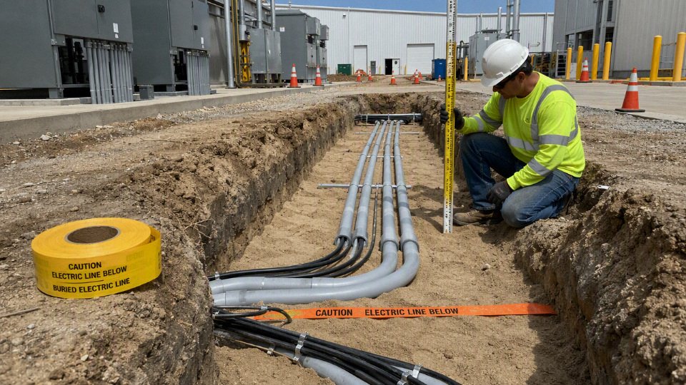
Authority and code hierarchy
The applicable burial rule is set by the authority that can approve, reject, energize, insure, or shut down the installation — not by the cable catalog alone. In practice, that means the NEC may be the starting document, but the final requirement can come from a city inspector, utility service guide, owner specification, mining regulator, port authority, or industrial safety department.
The authority having jurisdiction, usually shortened to AHJ, is not always one person in a pickup truck from the municipal inspection office. On a residential service trench, it may be the local electrical inspector and the serving utility. On a plant expansion, I have seen the practical “approval chain” include:
- Municipal or county electrical inspectors
- State electrical boards or licensing authorities
- Utility engineering departments for service laterals, metering, and transformer connections
- Industrial owner engineering standards groups
- Site safety, hazardous-area, or process safety departments
- Campus facility authorities for universities, hospitals, airports, and military sites
- Special regulators for mines, rail, ports, tunnels, petrochemical facilities, renewable energy plants, and public infrastructure
That matters commercially because a buyer can order perfectly good cable and still end up with rejected installation if the purchase was based on the wrong rule set. The cable may be listed, marked, and manufactured correctly, but if the trench depth, raceway type, separation from other services, mechanical protection, warning tape, transition detail, or hazardous-location wiring method does not match the adopted requirements, the installation is still exposed to rejection.
A cable product marking such as direct burial, sunlight resistant, or wet-location rated does not by itself approve every underground installation.True
Product marking addresses suitability of the cable construction for certain conditions, but the installed wiring method must still comply with the adopted electrical code, local amendments, utility requirements, protection rules, and inspection authority requirements.
The NEC is best treated as a model code until a jurisdiction adopts it. Many engineers quote the latest NEC edition during design review, then discover the city, state, or project contract is still enforcing an older edition with amendments. That is not a paperwork nuisance; it can change burial depth, GFCI protection assumptions, equipment grounding details, service rules, or inspection expectations. A procurement manager buying several truckloads of cable should not assume “NEC compliant” is specific enough unless the adopted edition and local amendments are named.
Different documents also do different jobs:
| Document or requirement source | What it usually controls | Practical procurement consequence |
|---|---|---|
| NEC | Premises wiring methods, minimum cover, protection, grounding, raceway fill, installation rules | Defines whether the selected cable and installation method are acceptable inside the facility boundary |
| NESC | Utility supply and communication lines, often on the utility side or for utility-owned systems | May govern service laterals, distribution circuits, or utility interfaces differently from the NEC |
| IEC-based standards | Common for international projects, export facilities, offshore interfaces, and multinational owner standards | Cable construction, test methods, voltage designation, and installation assumptions may not line up one-for-one with NEC terminology |
| Utility service guide | Metering, service entrance, transformer pads, conduit bends, trench route, pull boxes, ownership limits | Can override a neat design drawing if the utility refuses connection |
| Owner or industrial site specification | Site-specific durability, armor, jacket color, tray/raceway preference, documentation, spare capacity, hazardous-area practices | Often stricter than code because the owner is managing maintenance risk over decades |
| Manufacturer installation instructions | Pulling tension, bending radius, sidewall pressure, temperature limits, sealing, termination practices | Violating these can damage the cable even if the code pathway looks acceptable |
Where several documents apply, the strictest applicable requirement often governs, but “strictest” needs a careful read. A utility may require a larger conduit for service conductors than the electrical contractor planned, while the NEC may still control grounding and premises wiring once the service point is crossed. A petrochemical owner may require rigid metal conduit in an area where a general code reading would allow another raceway. A solar plant may have NEC requirements, utility interconnection rules, owner specifications, and environmental permit conditions all touching the same trench.
Before bulk cable procurement, freeze the compliance basis in writing: adopted code edition, jurisdiction, AHJ contact, utility standard, project specification revision, installation environment, approval documents, and inspection hold points. This is not bureaucracy for its own sake. It prevents the ugly version of value engineering: cheaper cable bought early, then field changes paid later through splice kits, extra conduit, re-trenching, schedule slippage, and arguments over who “should have known.”
For international projects, the risk shifts slightly. An IEC-designated cable may be exactly right for the country of installation, but if equipment skids, packaged substations, or owner standards reference NEC practices, the interface must be checked. Voltage rating, conductor identification, armor bonding, flame performance, and direct-burial suitability are not always interchangeable across standards by simple name matching.
The safest working habit is to build a short approval matrix before issuing the purchase order:
- Identify the legal jurisdiction and adopted electrical code edition.
- Confirm whether local amendments change underground wiring requirements.
- Obtain the utility service guide for any utility-owned or utility-connected portion.
- Review owner standards for harsher requirements than minimum code.
- Check environmental conditions: wet soil, chemical exposure, vehicular traffic, freeze depth, corrosive backfill, or hazardous classification.
- Match cable marking and listing to the actual wiring method, not just the desired trench route.
- Record who must inspect or approve before backfill.
- Keep manufacturer installation limits with the construction package, especially bending radius and pulling tension.
A clean code hierarchy saves more money before the cable is bought than after the trench is open. Once reels are on site, every unresolved authority question becomes a schedule risk.
NEC burial depth rules
NEC burial depth is applied as “minimum cover,” not simply trench depth. For many 600 V-and-under installations, NEC Table 300.5 commonly puts required cover somewhere from about 6 in to 24 in, depending on wiring method, circuit rating, GFCI protection, traffic exposure, and whether the installation is a special occupancy with its own article requirements.
Minimum cover is the distance from the finished grade, pavement surface, or slab surface down to the top of the cable or raceway. That sounds simple until the crew is standing beside an open trench with sand bedding, a 2 in PVC conduit, bell ends, sweeps, and a skid-steer operator waiting to backfill. Trench depth is deeper than cover because it must include:
- Bedding below the cable or raceway, if specified.
- The outside diameter of the conduit or cable assembly.
- Space for warning tape or marking where required by the project.
- Backfill allowance if settlement or final grading will reduce cover.
- Extra depth at sweeps, couplings, long-radius elbows, and transition points.
A common field mistake is measuring to the trench bottom and assuming the installation passes. If the trench is 18 in deep and the raceway outside diameter is roughly 2.4 in with a small bedding layer below it, the actual cover to the top of the raceway may be closer to 14 or 15 in after final grade is dressed. Inspectors normally care about the cover over the installed wiring method, not the depth of the excavation.
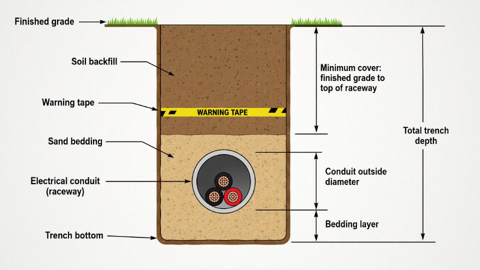
The main NEC reference for ordinary underground wiring is Table 300.5, but the table is not one single depth. It is organized around wiring method and location. The practical categories buyers and engineers usually need to separate are:
| Installation category | How it is generally treated in NEC burial-depth decisions | Practical procurement and installation note |
|---|---|---|
| Direct-buried cable or conductors | Often requires the greatest cover in ordinary locations, commonly up to 24 in depending on location and circuit type | Cable must be identified for direct burial and wet locations. “Outdoor” or “sunlight-resistant” marking alone is not enough. |
| Rigid metal conduit | Often allowed with relatively shallow cover in many ordinary locations because it provides strong mechanical protection | Corrosion protection, threaded joints, coating damage, and bonding continuity matter as much as depth. |
| Intermediate metal conduit | Treated similarly to rigid metal conduit in many Table 300.5 applications | Good mechanical protection, but still needs correct fittings and corrosion control underground. |
| Rigid nonmetallic conduit | Commonly PVC or similar listed raceway; usually needs more cover than rigid metal conduit but less than many direct-buried cable cases | Check schedule, listing for direct burial, expansion, thermal movement, and physical protection where emerging from grade. |
| Residential branch circuits, 120 V or less | A special reduced-cover case may apply only when GFCI protection and overcurrent limits are met | Do not apply this shortcut to feeders, 240 V loads, shops, pumps, or industrial branch circuits unless the exact conditions match. |
| Low-voltage landscape, irrigation, or control circuits | May have reduced cover where voltage, cable type, and circuit limits match the NEC table and related article rules | “Low voltage” does not automatically mean “no code issue,” especially around pools, docks, farms, or commercial sites. |
The reason the table treats wiring methods differently is mechanical protection. A direct-buried cable relies mostly on its jacket, insulation system, burial rating, and soil protection. A rigid metallic raceway gives the conductors a much tougher barrier against shovel strikes, rocks, shallow grading, and incidental vehicle loads. That is why a shallower metal raceway installation may comply while a deeper direct-buried cable route still does not.
Depth is not a substitute for using the correct wiring method. If the cable is not listed for direct burial, or if individual conductors in an underground raceway are not rated for wet locations, putting them deeper in the ground does not fix the violation. Underground raceways are generally considered wet locations under NEC practice, because condensation and water entry are expected over the life of the installation. Anyone who has pulled old conductors from a “sealed” PVC run after a freeze-thaw season knows how optimistic perfect dryness can be.
The residential branch-circuit exception is one of the most misused parts of burial-depth discussions. NEC Table 300.5 includes a reduced-cover path for residential branch circuits rated 120 V or less with GFCI protection and limited overcurrent protection, commonly understood around the 20 A maximum condition in the table. This is intended for a narrow class of residential branch circuits, not for a detached garage feeder, a well-pump feeder, a workshop subpanel, a commercial sign circuit, or an industrial control circuit feeding outdoor equipment.
The mechanism is risk reduction. GFCI protection reduces shock hazard when leakage occurs, and the overcurrent limit caps available fault energy compared with larger feeders. The trade-off is that the installation becomes condition-dependent: change the breaker size, circuit voltage, load type, occupancy, or wiring method, and the reduced-cover assumption may disappear. In practice, I want the panel schedule, breaker rating, wiring method, and intended load all checked before anyone tells a trenching contractor to hold shallow grade.
Vehicle and excavation exposure change the conversation. Driveways, parking lots, alleys, streets, commercial yards, farm lanes, and loading areas may need greater cover or a more protective raceway system than a lawn route beside a house. The concern is not only tire load directly crushing the conduit. It is the entire service life of the area:
- Pavement may be milled, resurfaced, or cut for drainage later.
- Gravel lots get regraded, often by someone who has never seen the electrical drawings.
- Farm lanes see rippers, fence-post drivers, augers, and seasonal mud movement.
- Commercial yards may change from passenger vehicles to forklifts, yard tractors, or container handling.
- Landscape zones get irrigation repairs, edging, root removal, and stake driving.
For these areas, the design should consider cover, raceway strength, warning tape, route marking, and damage protection at transitions. Warning tape is often placed roughly 12 in above the cable or raceway where the project specification or local practice requires it, but tape is a warning measure, not mechanical protection. If the backhoe bucket reaches the tape and the operator is moving fast, the remaining margin may be gone in one pass.
Special occupancies can override the simple Table 300.5 conversation. Swimming pools, spas, fountains, marinas, docks, agricultural buildings, hazardous classified locations, and similar environments bring in other NEC articles and equipment-specific restrictions. Around pools and spas, separation from the pool wall, bonding, GFCI protection, corrosion, and permitted wiring methods can matter as much as burial depth. At marinas and docks, shore power exposure, movement, wet-location deterioration, ground-fault protection, and corrosion are central issues. In agricultural buildings, moisture, corrosive atmospheres, livestock damage, and washdown practices affect raceway and cable selection. Hazardous locations may require wiring methods and seals determined by the classified area, not by ordinary burial-depth preference.
A deeper trench does not make an unlisted cable acceptable for underground installation.True
NEC underground compliance depends on both minimum cover and the wiring method being suitable for the environment. Direct-buried cables must be identified for that use, and conductors in underground raceways generally need wet-location ratings.
Rigid nonmetallic conduit deserves separate attention because it is so common in residential and light commercial work. PVC raceway can be economical, corrosion-resistant, and fast to install, but it is not all the same. The buyer or installer has to verify the raceway is listed for direct burial, that the correct schedule is used where physical damage is likely, and that above-grade risers are protected. A typical bad installation is neat underground PVC with a weak exposed stub-up at the wall, cracked by a mower, pallet jack, or snow shovel. The burial depth was fine; the transition failed.
Conduit fill is a related procurement issue, even though it is not the cover rule itself. Upsizing a raceway for conductor fill, pulling tension, voltage drop, or future circuits changes the outside diameter and therefore the trench depth needed to maintain the same cover. For common residential and light commercial raceways, the 40 percent maximum fill rule often applies where more than two conductors are installed, but the actual calculation depends on conductor size, insulation type, raceway type, and the applicable NEC chapter tables. If the estimator selects the conduit after the trench depth is priced, the project can end up with either inadequate cover or extra excavation cost.
The counter-intuitive part is worth saying plainly: a shallow installation can pass and a deep installation can fail. Six inches of cover over rigid metal conduit in a permitted location may be acceptable under the table, while 30 in of cover over indoor-rated cable in a muddy trench is still wrong. The same goes for missing bushings, wrong transition fittings, unprotected risers, unsuitable direct-burial markings, failed corrosion protection, or conductors not rated for wet locations.
Use NEC Table 300.5 as the starting point, then check the specific NEC article for the occupancy, the local amendment, the project specification, and the inspector’s interpretation before releasing cable or conduit for purchase. On a clean drawing this is a code lookup; on a jobsite it is a coordination item between engineering, procurement, trenching, and inspection.
Cable and raceway choices
The code-compliant product is the one whose listing, markings, and installation method match the burial condition, not simply the one that fits the trench depth. For underground work, assume wet service, soil exposure, mechanical abuse at transitions, and inspection of the actual cable print legend or reel documentation. That is where many technically “good” cables fail procurement review.
Underground cable selection usually breaks into two families: cable assemblies that are listed for the burial method, and individual conductors pulled into a raceway system. They are not interchangeable on a bill of material. A cable assembly carries its own construction, jacket, and use rating; individual conductors rely on the raceway for physical routing and, in some cases, mechanical protection.
THHN insulation alone does not automatically make an individual conductor suitable for underground installation.True
Underground raceways are generally treated as wet locations. A conductor marked only THHN is a dry/damp-location product; many building wire products are dual-marked THHN/THWN or THHN/THWN-2, but the wet-location marking must be verified on the conductor print legend or manufacturer documentation.
Common underground product choices look like this in practice:
| Product type | Where it is typically considered | Main selection checks |
|---|---|---|
| Direct-burial cable | Branch circuits, feeders, controls, site lighting, irrigation-related power where permitted | Direct burial marking, wet-location rating, voltage rating, jacket toughness, sunlight resistance at exposed ends |
| Underground feeder cable | Residential and light commercial feeders, outbuildings, small panels | Correct type for the jurisdiction, conductor size, equipment grounding conductor, temperature limitations, termination compatibility |
| Service entrance cable suitable for underground use | Utility/customer service laterals where accepted by the authority or utility | Service rating, underground use marking, neutral construction, utility specification, pulling tension limits |
| Individual conductors in conduit | Commercial feeders, industrial equipment, long runs, installations needing replacement access | Wet-location conductor rating such as THWN-2, conduit fill, derating, pulling calculation, raceway sealing and drainage |
| Armored or metal-clad options where permitted | Industrial sites, hazardous or abuse-prone areas, special transitions | Listing for direct burial or wet location, corrosion protection, grounding path, bend radius, gland system |
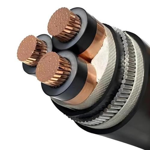
| Engineered medium-voltage cable systems | Plant distribution, substations, wind/solar collection, utility feeders | Insulation level, shield design, concentric neutral or ground wires, jacket, terminations, splices, test plan |
The mechanism behind the selection is simple but unforgiving: water gets into underground systems. Even glued PVC runs breathe with temperature swings, duct banks collect condensation, and low points become sumps unless the installation is designed otherwise. That is why the conductor insulation, jacket, shield, splice kit, and termination all need to tolerate a wet environment, not just the conduit wall.
Cable markings deserve more attention than they usually get at receiving inspection. For a proper purchase specification, the buyer should call out the required:
- Direct burial suitability, if the cable will be placed in earth without raceway.
- Wet-location rating for any cable or conductor installed underground.
- Voltage rating, including system voltage and any medium-voltage insulation level requirement.
- Temperature rating, with attention to both ampacity tables and actual termination limits.
- Conductor material, stranding class, and compact or concentric construction where relevant.
- Insulation type and jacket or sheath material.
- Sunlight resistance for cable emerging at poles, pads, walls, or tray transitions.
- Oil resistance, flame performance, low-smoke or halogen restrictions where the route enters industrial equipment rooms, tunnels, or buildings.
- Manufacturer, production batch, length marking, and traceability data.
I have seen procurement teams approve a cable based on conductor size and price, then discover on site that the print legend lacked the exact wet-location or direct-burial wording the inspector expected. That becomes an expensive argument because the trench is already open, the rental excavator is idling, and nobody wants to own the delay.
Raceway choice is the other half of the decision. PVC Schedule 40 is common underground because it is economical, corrosion-resistant, and easy to cut and glue. PVC Schedule 80 is normally chosen where the raceway is subject to physical damage, such as risers, pole bases, and exposed sections near equipment. Rigid metal conduit and intermediate metal conduit give better impact resistance and a more robust equipment grounding path, but they bring corrosion-control details, threaded joints, weight, labor, and cost. High-density polyethylene conduit works well for long directional bores and continuous duct runs, provided the fittings, bends, pulling method, and local acceptance line up. Fiberglass conduit can be attractive in corrosive soils or certain industrial sites, but crews need the right cutting, joining, and support practices. Concrete-encased duct banks are a different class of work: they are chosen for multiple circuits, road crossings, substations, campuses, and high-value feeders where alignment, heat dissipation, spare ducts, and civil coordination matter as much as the cable itself.
Mechanical protection often decides the raceway even after the electrical design is settled. The weak points are rarely in the middle of a clean trench. They are at:
- Risers from below grade to a wall, rack, pole, or pedestal.
- Building entries where settlement, sleeve edges, and sealing compounds can stress the cable.
- Pole bases and lighting standards exposed to mowers, pallet jacks, snow removal, or forklifts.
- Equipment pads where conduits emerge before the gear is set.
- Roadway and driveway crossings where cover may be disturbed later.
- Exposed transition points between underground duct, tray, cabinet, and flexible connection.
At those locations, a cheap raceway can become the most expensive part of the job. Schedule 40 PVC in a clean trench may be fine; the same material standing 900 mm above grade beside a loading dock is asking to be broken.
Conductor material is a commercial decision as much as an electrical one. Copper gives higher ampacity for a given size, better conductivity, smaller terminations, and generally easier handling in crowded gear. Aluminum can reduce material cost and weight, especially on long feeders, but it usually needs larger conductor sizes, correct lugs, oxide inhibitor where specified by the termination manufacturer, torque discipline, and more space in conduit and enclosures. Voltage drop can flip the preference. A long aluminum feeder may still be cheaper after upsizing, but a short, congested equipment connection may favor copper because the installation labor and enclosure fit dominate the material saving.
The boundary is termination quality. Aluminum installed with listed terminals, proper preparation, correct torque, and compatible environments performs very differently from aluminum treated like oversized copper. For overseas projects, I would rather see the connector specification, torque method, and inspection record included in the package than rely on someone’s memory at the jobsite.
From a cable manufacturer’s side, the purchase order should not stop at “underground cable, 600 V” or “MV cable, direct burial.” A serious buyer should specify the governing standard, conductor class, conductor material, insulation system, sheath or jacket design, color or core identification, packing method, drum length tolerance, factory test reports, marking language, and traceability requirements. For medium-voltage systems, include accessories and interface requirements early: shield grounding method, termination type, splice design, cable pulling plan, and acceptance testing all affect whether the installed system behaves as designed.
Jinda’s role in a project procurement discussion is strongest when the buyer provides the duty conditions rather than only a size list: installation method, burial environment, circuit voltage, conductor preference, required standards compliance, documentation requirements, packaging limits, and planned drum lengths. With manufacturing, technical support, and after-sales service integrated across large-scale production bases, that is the information needed to turn a generic cable request into a buildable, inspectable supply package.
Inspector installation checkpoints
Before digging: paperwork and route control
- Utility locating and private locating: Public one-call marking is not enough on many plants and larger sites. Old feeder stubs, irrigation wiring, abandoned lighting circuits, plastic gas branches, and owner-installed fiber often never made it into the public utility records. For industrial yards, I like a private locator sweep before trenching, especially near substations, loading docks, tank farms, and old building additions.
- Permits and inspection hold points: Confirm the permit, inspection stages, and whether the inspector wants to see the trench before bedding, before conduit cover, or before final backfill. A good installation can fail schedule-wise if the trench is covered before the required observation.
- Route approval: The approved drawing should match what the crew is about to dig. Watch for last-minute routing around landscaping, footings, storm drains, security bollards, future pads, or forklift paths. “Close enough” routing becomes expensive when the as-built later conflicts with a foundation or utility corridor.
- Trench safety planning: Sloping, shielding, spoil placement, water control, and equipment access need to be planned before the excavator arrives. Electrical inspectors may not be the trench-safety authority, but an unsafe trench can stop the job cold.
- Soil and drainage review: Rocky fill, cinders, demolition debris, high groundwater, clay that holds water, or corrosive soil can change bedding, conduit selection, corrosion protection, and handhole details. Underground raceways and cables are treated as wet-location installations in practice because water eventually gets in.
Trench preparation and backfill
The trench bottom should be smooth, reasonably uniform, and free of broken concrete, scrap rebar, sharp stone, metal strapping, glass, and construction trash. Direct-buried cable is especially vulnerable here, but PVC and coated metal raceway can also be damaged by point loading when backfill is compacted.
Typical inspection points include:
- Bedding: Sand, screened soil, or other specified bedding should support the cable or raceway continuously, not just at high spots.
- Separation: Maintain required spacing from water, gas, communications, steam, fuel, drainage, and other power systems according to the governing specification and local rule.
- Controlled backfill: The first lift over the cable or raceway should not contain rocks, brick, scrap metal, or chunks of hardened concrete. Dumping mixed site spoil straight from the loader bucket is a common way to create future faults.
- Compaction: Backfill must meet the civil requirement without crushing raceway or distorting ducts. Heavy compaction directly over shallow conduit is a bad habit; use staged lifts and the right equipment.
- Drainage: Avoid creating a trench that behaves like a French drain into a handhole, basement wall penetration, or equipment pad. If water will collect, the enclosure and raceway system must be selected and sealed with that condition in mind.
Pulling quality: bends, tension, and insulation damage
Most underground failures I have seen were not caused by the catalog rating of the cable. They came from rough handling, too many bends, overloaded pulls, incompatible lubricant, or a crew trying to save time with the backhoe bucket still swinging nearby.
Check these items before and during the pull:
- Minimum bend radius: Verify against the cable manufacturer’s data, not a rule of thumb from a different cable type. Shielded medium-voltage cable, armored cable, and large conductors are less forgiving than small branch-circuit conductors.
- Pulling tension: Long runs, multiple bends, and large conductors can exceed allowable tension quickly. Use pulling calculations or manufacturer guidance where the run is substantial.
- Sidewall pressure: A pull can be within total tension limits and still damage insulation at bends if sidewall pressure is excessive.
- Lubricant compatibility: Pulling compound should be compatible with the cable jacket and raceway. Random grease, dish soap, or plant maintenance lubricant has no place in a code installation.
- Reel handling: Roll reels the correct direction, support them on jacks, and avoid dragging cable across gravel or steel edges.
- End sealing during work: Keep moisture and mud out of cable ends and conduits. On wet sites, even an overnight open end can create a problem that shows up during insulation resistance testing.
The trade-off is simple: tighter routing saves trench length, but every bend increases pulling risk and future replacement difficulty. That saving stops being attractive when the run cannot be pulled without damaging the cable or when no practical replacement path remains.
Raceway details inspectors notice
Raceway work is where small workmanship errors become obvious. A straight trench with the right depth can still fail if the conduit system is poorly assembled.
Key checks include:
- Conduit fill: Verify fill using the actual conductor outside diameters and the raceway size. For many residential and light commercial runs, the familiar 40 percent maximum fill condition applies when more than two conductors are installed, but the exact rule must be checked against the applicable code article and wiring method.
- Conductor derating: Multiple current-carrying conductors, ambient conditions, and raceway grouping can reduce allowable ampacity. This is often missed when spare conduits become “temporary” added circuits later.
- Spare capacity: Procurement teams like minimum conduit because it lowers material cost. Maintenance teams usually regret it. Spare duct or larger raceway can be cheap during trenching and painfully expensive after paving.
- Expansion fittings: Long PVC runs, transitions between exposed and buried sections, bridge crossings, and building entries may need expansion or expansion-deflection fittings. Temperature swing matters; a sunny exterior wall can move more than people expect.
- PVC solvent cement practice: Joints should be clean, properly primed where required, fully seated, and given suitable cure time before pulling. Half-glued joints may pass a glance and still separate during backfill or cable pulling.
- Metal raceway protection: Rigid steel, intermediate metal conduit, coated conduit, and fittings need corrosion protection suitable for the soil and exposure. Scratched coatings at wrench marks and field cuts deserve attention.
- Bonding continuity: Metallic raceways, boxes, fittings, equipment grounding conductors, and bonding bushings must create a reliable fault-current path. Paint, corrosion, loose locknuts, and mismatched fittings are common weak points.
Splices, handholes, boxes, and enclosures
Underground splices should be avoided where practical, but when they are needed, they must use products listed and rated for the actual condition: wet location, direct burial where applicable, handhole use, submersible exposure if water accumulation is expected, and the conductor material involved. A dry-looking box at installation is not proof it will stay dry after a season of rain, irrigation, frost movement, or a blocked storm drain.
Inspectors commonly look for:
- Listed splice kits matched to conductor size, insulation type, voltage class, and copper or aluminum conductor material.
- Pull boxes and junction boxes sized for the conductors and pulling geometry.
- Handholes rated for the expected traffic loading, not just foot traffic if vehicles, pallet jacks, or mowers can cross them.
- Covers secured and marked where required.
- Drainage or sealing strategy consistent with the enclosure rating and site water conditions.
- Cable support and slack that prevent strain on terminations when soil settles.
Underground raceway interiors should be assumed wet during product selection and installation planning.True
Electrical codes and standard industry practice treat underground raceways as wet locations because condensation, groundwater, and water migration through joints or entries are expected over the service life. Product ratings and conductor insulation must be selected accordingly.
Above-ground transitions and physical protection
Risers are easy to underestimate because they look simple on the drawing. In service, they take hits from string trimmers, pallet forks, snow removal, carts, vehicles, and maintenance people using them as accidental handholds.
Check protection at:
- Risers from grade: Use suitable rigid protection where the wiring method emerges from the ground and is exposed to damage.
- Wall penetrations: Seal against water entry, protect the cable or raceway edge, and coordinate with firestopping where the wall assembly requires it.
- Equipment entries: Avoid low points that drain into panels, disconnects, meter bases, or control cabinets. Drip loops, hubs, sealing fittings, and proper entries matter.
- Meter and service areas: Utility rules may be stricter than the general electrical code. Confirm meter socket height, conduit type, grounding, and service lateral details with the utility.
- Vehicle and lawn equipment exposure: A riser beside a driveway, dock, or mower path needs more than “normal” protection. If the first damaged part is the raceway, not the cable, you designed it correctly.
Identification and records
Identification is not cosmetic. It prevents accidental excavation damage, shortens troubleshooting time, and gives the next project engineer a fighting chance.
A defensible underground installation should include:
- Warning tape placed above the cable or raceway where required by specification or local practice; roughly 12 in above the run is common, but project documents govern.
- Tracer wire for nonmetallic systems where specified, especially for long private routes.
- Route markers at changes of direction, road crossings, handholes, and service points where permanent marking is practical.
- Cable tags at terminations, pull boxes, handholes, switchgear, panels, and equipment.
- Phase identification and circuit identification that match drawings and panel schedules.
- As-built drawings showing actual route, depth, handholes, spare conduits, and deviations from the issued plan.
Final inspection and testing before energizing
Before backfill, document installed depth with photos, marked grade references, or inspector observation as required. Once backfilled, no one wants to argue from memory about whether the cover was correct.
Final checks usually include:
- Visual inspection: Verify burial depth, bedding, raceway assembly, warning tape, transitions, box ratings, covers, bonding, and workmanship before concealment.
- Continuity checks: Confirm conductors, equipment grounding conductors, bonding jumpers, and raceway bonding where metallic raceway is used.
- Insulation resistance testing: Use where appropriate for the cable type, voltage class, owner specification, and manufacturer guidance. Record test voltage, duration, temperature if relevant, and readings.
- Torque verification: Terminations should be torqued to the equipment manufacturer’s values using a calibrated torque tool, especially on aluminum conductors and larger feeders.
- GFCI testing: Test required GFCI protection with the installed load arrangement, not just with the device button in isolation.
- Documentation package: Keep permits, inspection signoffs, test reports, as-built drawings, product data, splice kit records, and photos of the open trench.
The practical limit of any checklist is that it cannot rescue a design that ignored soil, water, traffic loading, or maintenance access. Field inspection works best when the installer, inspector, engineer, and owner agree on the hold points before the trench is open and the backhoe is waiting.
Electrical protection requirements
A buried cable can meet the required cover depth and still be unsafe if the circuit protection is wrong. The electrical design has to prove that the conductor can carry the load, the breaker or fuse will clear faults, exposed metal will bond correctly, and the installed route will not overheat or suffer excessive voltage drop in service.
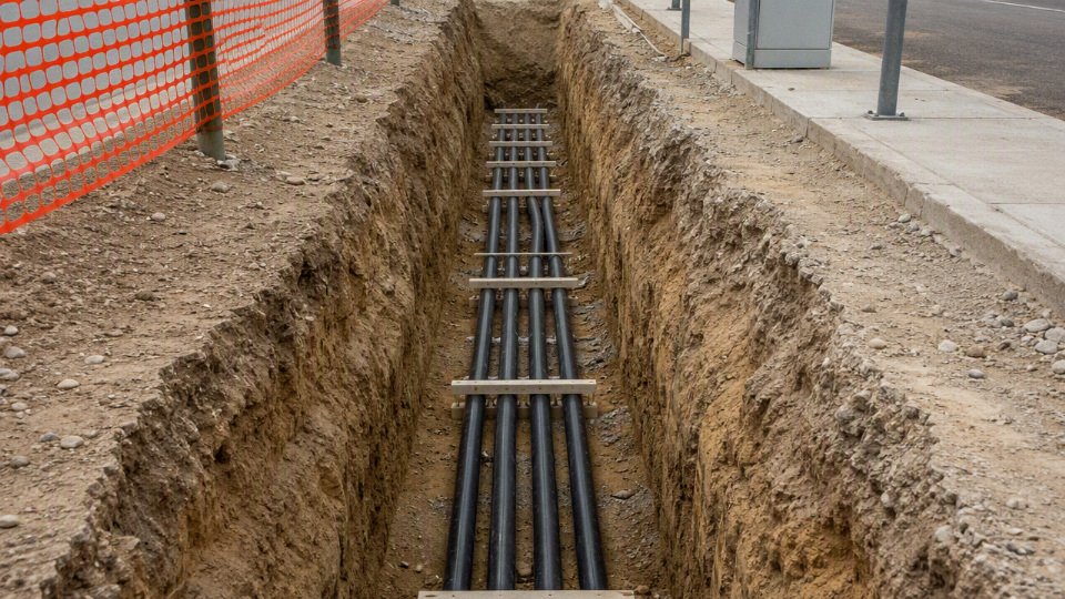
Conductor ampacity starts with the connected load, but it is not just a nameplate-current exercise. A proper selection normally checks:
- Load type and duty cycle: continuous lighting, EV charging, telecom shelters, lift pumps, and process motors load a feeder very differently from an occasional gate operator.
- Conductor material: copper and aluminum may both be acceptable, but aluminum needs larger sizes for the same ampacity and more attention to terminations, oxide control, and torque.
- Insulation temperature rating: many cables have 75°C or 90°C insulation ratings, but the usable ampacity may be limited by 60°C or 75°C equipment terminations.
- Number of current-carrying conductors: extra phase conductors, shared neutrals, or multiple circuits in one raceway can trigger derating.
- Ambient and installed temperature: underground does not mean cool. Dry soil, shallow cover in sun-exposed areas, and packed duct banks can run hotter than people expect.
- Raceway layout: single conduit in soil behaves differently from four conduits grouped tightly under a driveway or several feeders in a concrete-encased duct bank.
The breaker protects the conductor, not the equipment salesperson’s preferred cable size. Overcurrent protection must allow normal starting and operating current while still opening before the conductor insulation is damaged during overloads or faults. This is where mistakes show up on plant floors: a motor feeder gets upsized for voltage drop, someone matches the breaker to the larger conductor without checking equipment limits, or a small control circuit is tapped from a larger feeder without proper protection. Motors, transformers, welders, and HVAC loads often have special rules, so the protective device size may not equal the simple ampacity number.
Grounding and bonding are just as important underground because faults do not care that the raceway is buried. The design should identify:
- Equipment grounding conductors in feeders and branch circuits, including size and continuity through pull boxes, handholes, and equipment cabinets.
- Bonding of metal raceways and enclosures, especially where PVC transitions to rigid metal at risers, pole bases, service gear, or exposed industrial areas.
- Service equipment bonding and grounding electrode connections, which must not be improvised in the field because a ground rod alone is not an effective equipment grounding conductor.
- Detached structures, where feeders usually need an equipment grounding conductor and correct grounding electrode system treatment.
- Separately derived systems, such as transformers or generators feeding remote buildings, where bonding location and neutral treatment need deliberate design.
Ground-fault and GFCI protection requirements vary by occupancy, voltage, circuit type, and local amendments. Residential outdoor receptacles and many garage, pool, spa, and landscape circuits commonly need GFCI protection. Construction sites often require stricter temporary-power protection. Marinas, boatyards, agricultural buildings, washdown areas, and some industrial wet-process zones deserve special review because moisture, metallic structures, livestock contact voltage, and personnel exposure change the risk profile. Nuisance tripping is not a reason to omit protection; it is a reason to find leakage, damaged insulation, shared neutrals, water-filled boxes, or the wrong protective device type.
Long underground routes also need voltage-drop checks. Feeders to pumps, irrigation pivots, lift stations, parking-lot lighting, EV charging pedestals, telecommunications shelters, and remote maintenance buildings can be electrically legal but operationally poor if the voltage at the load sags under starting current. Motors may run hot, contactors may chatter, LED drivers may fail early, and EV chargers may derate or fault. The usual trade-off is simple: larger conductors reduce voltage drop and heat, but increase cable cost, conduit size, pulling tension, termination hardware, and sometimes gear lug requirements. The preferred answer can flip when the trench is already open and labor dominates cost; upsizing at procurement may be cheaper than revisiting a 250-meter run later with a crew and a locator.
Thermal behavior is the part that gets underestimated in heavy industrial work. Soil thermal resistivity, moisture content, duct-bank grouping, concrete encasement, conductor load factor, and mutual heating all affect how fast heat leaves the cable. A lightly loaded branch circuit in one PVC conduit may be handled with standard code ampacity methods, but medium-voltage feeders, high-load low-voltage feeders, parallel conductors, and dense duct banks often need engineered ampacity calculations using project-specific assumptions. The boundary is worth stating: ordinary code tables are minimum compliance tools, not a guarantee that every buried cable arrangement will run cool under continuous industrial load.
Long outdoor cable routes also invite surge and transient problems. Lightning does not have to strike the cable directly to induce damaging voltage in a long feeder or control cable. Remote pump panels, gate operators, lighting controls, PLC cabinets, security systems, EV charging equipment, and telecom shelters may need surge protective devices, coordinated grounding, shield bonding decisions, and physical separation between power and signal circuits. In practice, I would rather see surge protection and bonding discussed during design than after the maintenance team has replaced the same control board twice during storm season.
Site failure risks
Minimum burial depth keeps the installation legal; it does not guarantee service life. Premature underground cable failures usually come from water, mechanical abuse, chemicals, corrosion, heat, or a handoff gap between the civil crew and the electrical crew. For critical feeders, the risk review should be done before trenching, not after the cable is already on the reel.
Moisture is the first failure mode I look for because underground raceways are wet locations in practice, even when they look dry on the drawing. Water enters through imperfectly sealed splices, damaged jackets, poorly fitted duct seals, cracked handhole lids, and conduit systems that “breathe” with daily temperature swings. Condensation can collect in low points of conduit, then sit against terminations or splice bodies for years. Flooded handholes are common in parking lots and plant yards where drains clog with silt.
The detail that gets missed is capillary action. Water can travel along conductor strands, shield interfaces, braid, or armor layers if the cable construction and accessories are not selected to block it. A cable that is acceptable indoors may age quickly underground if its insulation, jacket, tapes, or fillers are not rated for wet locations and direct burial conditions where applicable.
A buried raceway should be treated as a wet location for cable selection.True
Underground conduit systems routinely collect water through condensation, leakage, and flooding, so wet-location-rated conductors and suitable accessories are normally required by code and good engineering practice.
Mechanical damage is more varied. Rocks in native backfill can press into the sheath as the soil settles. Poor compaction leaves voids that later collapse under forklift lanes, yard trucks, or seasonal ground movement. Frost heave can bend conduits and pull on terminations. Directional drilling can scar a duct or over-pull a cable if bore alignment and pulling tension are not controlled. Rodents are not a theoretical issue either; I have seen gnaw marks on polymer jackets in utility corridors and agricultural sites.
Later excavation is often the most expensive mechanical risk because it happens after everyone has forgotten the route. A shallow irrigation repair, fence post, sign base, or drain trench can cut a feeder that was perfectly compliant when installed. Warning tape, detectable tape, tracer wire, marker posts, and accurate as-built records are cheap compared with a night shutdown and emergency splice kit.
Chemical exposure changes the product choice. Hydrocarbons around fuel islands, fertilizers at farms and landscape areas, deicing salts near roads, industrial effluent, acids, alkalis, marine spray, and contaminated soil can attack jackets, metallic armor, screens, and terminations. Ultraviolet exposure also matters at risers where the cable or conduit emerges above grade; a direct-burial jacket is not automatically sunlight-resistant unless the product documentation says so.
Corrosion deserves its own review where soils are aggressive. Metallic conduit, armor, grounding electrodes, bare or concentric neutrals, and termination hardware can deteriorate in low-resistivity, high-chloride, acidic, alkaline, or stray-current environments. Galvanized rigid conduit may be a good mechanical solution in one plant and a maintenance problem in another. The right answer depends on soil data, drainage, coating system, cathodic protection requirements, and how the raceway transitions above grade.
Thermal aging is quieter but just as damaging. Undersized conductors, overloaded feeders, grouped ducts, poor heat dissipation in dry soil, and future load growth all raise conductor temperature. Insulation life is strongly affected by operating temperature; a feeder that runs warm every afternoon will not age like one carrying intermittent load. The trade-off is straightforward: larger conductors, spaced ducts, spare conduits, or a better thermal backfill cost more at installation, but they protect capacity and avoid forced replacement when production adds another line or charger bank. This conclusion stops holding where loads are genuinely temporary, duty cycle is low, and the owner accepts limited expansion capacity in writing.
A practical prevention package should include:
- Route planning: avoid fuel areas, hot process zones, future building pads, deep-rooted landscaping, and known excavation corridors where possible.
- Environmental assessment: check groundwater, soil chemistry, contamination history, frost depth, traffic loading, and drainage before final cable selection.
- Suitable cable and sheath materials: specify wet-location suitability, direct-burial rating where needed, sunlight resistance at risers, oil or chemical resistance where exposure is credible, and armor or duct protection where mechanical risk is high.
- Sealed accessories: use splice kits, glands, duct seals, and terminations rated for the voltage, environment, and installation method; do not let a bargain splice become the weak point in an expensive feeder.
- Spare ducts and pull points: spare capacity is inexpensive while the trench is open and painful later under concrete or asphalt.
- Inspection hold points: verify trench bottom condition, separation, bedding, conduit joints, bend radius, warning tape location, backfill material, compaction, and photos before cover.
- Maintenance records: keep route drawings, depth notes, handhole locations, cable IDs, test reports, and repair history where maintenance staff can actually find them.
The awkward commercial risk is mixed responsibility. The cable supplier may provide a correct product, the electrical contractor may pull it properly, and the civil contractor may still shorten its life with sharp backfill, poor drainage, undocumented route changes, or compaction damage. Procurement documents should assign these interfaces clearly, because underground cable reliability is built as much in the trench as it is in the factory.
Procurement documentation checklist
Use the purchase specification to remove guesswork before quotations start. A buried cable RFQ that only says “suitable for underground use” will usually come back with uneven offers: different jacket grades, different test documents, different drum lengths, and sometimes a product that meets the catalog description but not the jobsite inspection requirement.
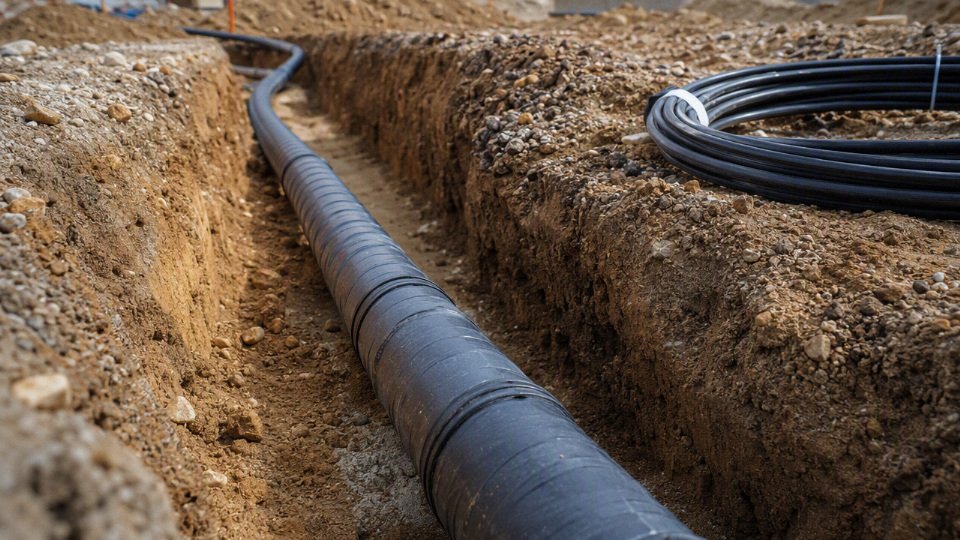
A practical procurement package should cover these items.
- Project and code basis
- Country, state or province, city, and project site location.
- Adopted code or standard: for example NEC edition, local electrical code, utility standard, IEC-based project specification, or client engineering standard.
- Authority having jurisdiction, inspection agency, utility reviewer, or engineer of record.
- Installation location:
- Residential service lateral.
- Industrial feeder.
- Outdoor lighting circuit.
- Pump, gate, process equipment, or renewable-energy connection.
- Indoor-to-outdoor transition through wall, slab, pole, handhole, or equipment base.
- Installation method:
- Direct burial.
- Underground raceway.
- Duct bank.
- Sleeve only at road crossing or exposed riser.
- Trench environment:
- Native soil or imported sand bedding.
- Wet ground, seasonal flooding, high water table, chemical contamination, hydrocarbons, rodents, termites, frost movement, or heavy vehicle traffic.
- Target service life and maintenance expectation. A temporary construction feeder and a 25-year plant power circuit should not be bought from the same one-line description.
- Electrical requirements
- Rated voltage, including system voltage and insulation class.
- AC or DC service, frequency if AC, and grounding arrangement.
- Conductor size and conductor material: copper or aluminum.
- Number of cores or individual conductors.
- Phase arrangement, neutral requirement, grounding conductor requirement, concentric neutral if applicable.
- Design ampacity, installation grouping, ambient temperature assumption, soil thermal condition if known, and derating basis.
- Maximum permitted voltage drop at full load or starting load.
- Short-circuit withstand requirement and fault duration where the engineer has specified it.
- Cable construction requirements
- Insulation material, such as XLPE, PVC, EPR, or project-specified equivalent.
- Jacket or sheath material and required resistance to moisture, abrasion, sunlight, oil, chemicals, or low temperature.
- Armor or metallic sheath requirement, if mechanical protection or grounding design calls for it.
- Water-blocking features for stranded conductors, screens, or interstices where long wet runs are expected.
- Flame rating for indoor transitions, tray sections, tunnels, equipment rooms, or risers.
- Low-smoke, zero-halogen, or halogen-free requirement where specified by the building, tunnel, rail, marine, or industrial owner.
- Temperature rating for normal operation and emergency or short-circuit condition, if defined by the design standard.
- Installation requirements
- Minimum cover required by code, specification, or local amendment. For NEC-based work, Table 300.5 commonly drives minimum cover values in the rough range of 6 in to 24 in depending on circuit type, wiring method, and protection, but the actual row must be checked.
- Raceway material and size, including conduit fill calculation. For many residential and light commercial underground raceway cases, 40 percent maximum fill is a common limit when more than two conductors are installed, but the project must verify the applicable rule.
- Pulling length, number of bends, bend radius, pulling direction, lubricant allowance, and maximum pulling tension.
- Required drum length, spare length at terminations, and whether factory-cut lengths must match a drum schedule.
- Termination and splicing method: lugs, glands, heat-shrink joints, cold-shrink joints, separable connectors, junction boxes, or handhole splices.
- Compatibility with accessories, including conductor stranding class, insulation diameter, shield construction, armor bonding method, and gland size.
- Documentation deliverables
- Manufacturer datasheet and construction drawing.
- Certificate of compliance to the quoted standard or project specification.
- Routine test reports for the supplied batch.
- Type test reports where required by the buyer, utility, or project engineer.
- Quality management certificates.
- Packing list, drum schedule, shipping marks, and net/gross weight.
- Cable marking details, preferably in English for international projects unless the contract specifies otherwise.
- Traceability records tying drum numbers to production batch, test records, and shipment documents.
- Installation recommendations covering storage, handling, pulling, bending, sealing, and termination precautions.
- Commercial and logistics requirements
- Total order quantity, tolerance on length, and spare cable percentage.
- Required delivery schedule, partial shipment rules, and hold points for document approval.
- Export packaging suitable for sea freight, including drum lagging, flange protection, waterproof wrapping, and corrosion protection for hardware.
- Batch consistency requirements where multiple shipments must match the same construction and marking.
- After-sales technical support scope: document clarification, product identification, handling guidance, and coordination on installation questions.
For bulk procurement, the cleanest RFQ is one that lets the manufacturer quote the same technical object the engineer intends to install. Jinda can support international buried cable projects with manufacturing traceability, bulk supply coordination, English project documentation, and technical communication across procurement and engineering teams. The local inspector, utility, and engineer of record still decide whether the selected cable and installation method satisfy the governing code at the jobsite.
Frequently asked questions
What is the minimum depth for buried electrical cable?
There is no single minimum depth that applies to every buried electrical cable. Under NEC Table 300.5, common minimum cover values often fall between 6 in and 24 in, depending on the wiring method, circuit type, GFCI protection, raceway type, and whether the area is subject to vehicle traffic.
NEC Table 300.5 gives one universal burial depth for all underground electrical cables.False
The required cover changes with wiring method, voltage, circuit rating, location, and mechanical protection. Local amendments and the authority having jurisdiction can also change what is accepted on a specific job.
Can I bury outdoor-rated cable without conduit?
Only if the cable is specifically listed and marked for direct burial, and the installation conditions match that listing. “Outdoor-rated” may only mean sunlight-resistant, moisture-resistant, or jacketed for exterior exposure; it does not automatically mean the cable can sit in wet soil for years.
Does underground cable need to be in conduit?
Not always. Direct-burial cable can often be installed without continuous conduit, but conduit is commonly used where the cable rises from grade, passes under paved areas, crosses high-risk zones, or needs added mechanical protection. In industrial plants, I usually prefer conduit or duct banks in traffic areas because one forklift-mounted trench plate dropped in the wrong place can turn a cheap installation into an outage.
Is PVC conduit acceptable underground?
Yes, listed PVC electrical conduit is widely used underground when installed to the correct burial depth, fill limit, support, transition, and expansion requirements. Schedule selection matters: light-duty PVC may be acceptable in protected soil, while heavier wall conduit or rigid metal may be needed where the raceway emerges from the ground or faces impact.
What cable is rated for direct burial?
Common examples include UF-B for many residential branch-circuit applications and USE-type conductors for certain underground service and feeder applications, subject to the limits of their listing. Some industrial power, control, tray, armored, and instrumentation cables are also available with direct-burial ratings, but the words “direct burial” or equivalent listing information must appear in the manufacturer documentation, not just in a distributor description.
Is THHN allowed in underground conduit?
Plain THHN by itself is not the right basis for an underground raceway, because underground conduit is treated as a wet location. Many building wires are dual-marked THHN/THWN-2; the wet-location rating is the part that makes them suitable. Check the printing on the insulation reel, not the purchase order shorthand.
Do buried electrical cables need warning tape?
Warning tape is often required by project specification, utility practice, or local inspection preference, even where the base electrical code language is more specific to certain installations. A common practice is to place detectable or clearly marked warning tape roughly 12 in above the cable or raceway, so an excavator bucket finds the warning before it finds the conductors.
Can electrical cable share a trench with water, gas, or communications lines?
Sometimes, but do not assume it. Shared trench rules depend on utility standards, local code, separation distances, burial depths, sleeve requirements, and ownership boundaries. Gas and electric separation is especially sensitive; communications circuits may be allowed in the same trench with spacing or separate raceways, but the details should be approved before trenching starts.
How deep should cable be under a driveway?
Driveways usually push the design toward deeper cover or stronger raceway protection because the cable is exposed to vehicle loading, settlement, and future pavement work. The exact depth depends on the wiring method and local code table, but a direct-burial cable that is acceptable in a lawn may not be acceptable under a driveway without extra protection.
Are underground splices allowed?
Yes, but only with splice kits, enclosures, or assemblies listed for wet locations and the specific underground use. Ordinary wirenuts, tape wraps, and “temporary” junctions buried in soil are maintenance traps. If a splice must be installed, document its location; six months later, nobody remembers the exact spot under the gravel.
Does low-voltage landscape lighting follow the same burial rules?
Low-voltage landscape lighting can have different burial provisions than premises power wiring, especially for listed systems operating at limited voltage. That does not make it rule-free. Use cable listed for the system, follow the transformer and lighting manufacturer’s instructions, and check local inspection requirements where the work is part of a permitted project.
Who approves the final burial method?
The authority having jurisdiction has the final say for code acceptance, with utility approval also required where utility-owned service conductors or service laterals are involved. Engineers, contractors, cable suppliers, and inspectors should align before procurement where possible, because changing from direct burial to conduit after cable delivery can affect conductor size, fill, pulling tension, accessories, labor, and inspection timing.
Verify your cable specification
Buried cable compliance is a verification path, not a shopping description. Before procurement or trenching, lock down the authority having jurisdiction, the adopted code edition, the approved wiring method, the minimum cover, the wet-location and soil-exposure ratings, and the records the inspector or owner will expect to see.
A practical final check looks like this:
- Identify the governing authority
- Local electrical inspector or authority having jurisdiction
- Utility requirements at service points or interconnections
- Project specification, insurance requirement, or owner standard
- Applicable national or regional code edition
- Confirm the wiring method
- Direct-burial cable, underground feeder cable, service-entrance cable, or individual conductors in raceway
- Rigid metal conduit, PVC, HDPE duct, concrete-encased duct bank, or other approved raceway
- Transition details where the system rises from grade, enters equipment, or passes under traffic areas
- Verify minimum cover and protection
- Burial depth based on the wiring method, circuit type, voltage, and mechanical protection
- Warning tape location if required by the project or local practice
- Physical protection at bends, risers, road crossings, building entries, and equipment pads
- Check the environment
- Wet-location rating
- Direct burial suitability if no raceway is used
- Soil chemistry, drainage, groundwater, freeze-thaw exposure, hydrocarbons, fertilizers, salts, or industrial washdown
- Rodent exposure and future excavation risk
- Document what will be installed
- Cable type and construction
- Conductor material and size
- Insulation and jacket system
- Voltage rating
- Raceway type and size
- Pulling lengths and bend limits
- Splice, termination, gland, and accessory requirements
- Inspection, test, and certification requirements
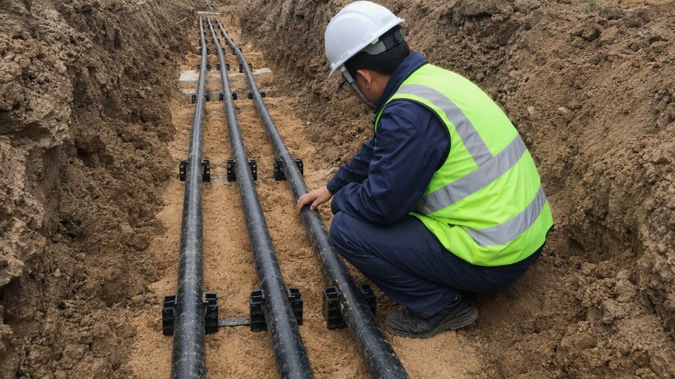
For buyers, the pre-purchase sequence should be short enough to use before issuing a purchase order, but complete enough to stop the usual mistakes:
- Application: feeder, branch circuit, service, pump supply, lighting, controls, renewable energy, or industrial power
- System voltage and phase
- Load current, duty cycle, and expected future capacity
- Route length, terrain, bends, and pull points
- Burial method: direct burial, conduit, trench, duct bank, or concrete encasement
- Cable construction: conductor, insulation, shield if applicable, armor if applicable, jacket, flame or oil resistance where required
- Raceway and conduit fill checks, especially where multiple conductors share one raceway
- Mechanical protection level: traffic loading, risers, exposed transitions, warning tape, marker posts
- Required tests: continuity, insulation resistance, sheath test, or project-specific acceptance testing
- Certificates, standards, markings, drum labeling, packing method, and delivery schedule
Do not buy buried cable only by conductor size or lowest unit price. I have seen perfectly good copper or aluminum cable become the wrong cable because the jacket was not suitable for the soil, the raceway fill was not checked, or the documentation did not match what the inspector wanted on site.
Escalate the specification to the engineer of record or a specialist when the project includes:
- Medium-voltage feeders
- Utility interconnections
- Hazardous classified locations
- Long high-load runs where voltage drop and thermal conditions matter
- Duct banks with multiple loaded circuits
- Hospitals, data centers, process plants, rail, ports, or other critical infrastructure
- Chemically aggressive soil or contaminated industrial ground
- International projects where NEC, IEC, local utility rules, and owner specifications overlap
For cable selection and quotation support, share the project drawings, code basis, electrical parameters, installation environment, required cable construction, accessory expectations, and procurement schedule with Jinda’s technical team. Clear route drawings, load data, soil or exposure notes, and any required standards or certificates will let the team review the application, recommend suitable cable options, and prepare a quotation aligned with the installation conditions rather than only the conductor size.