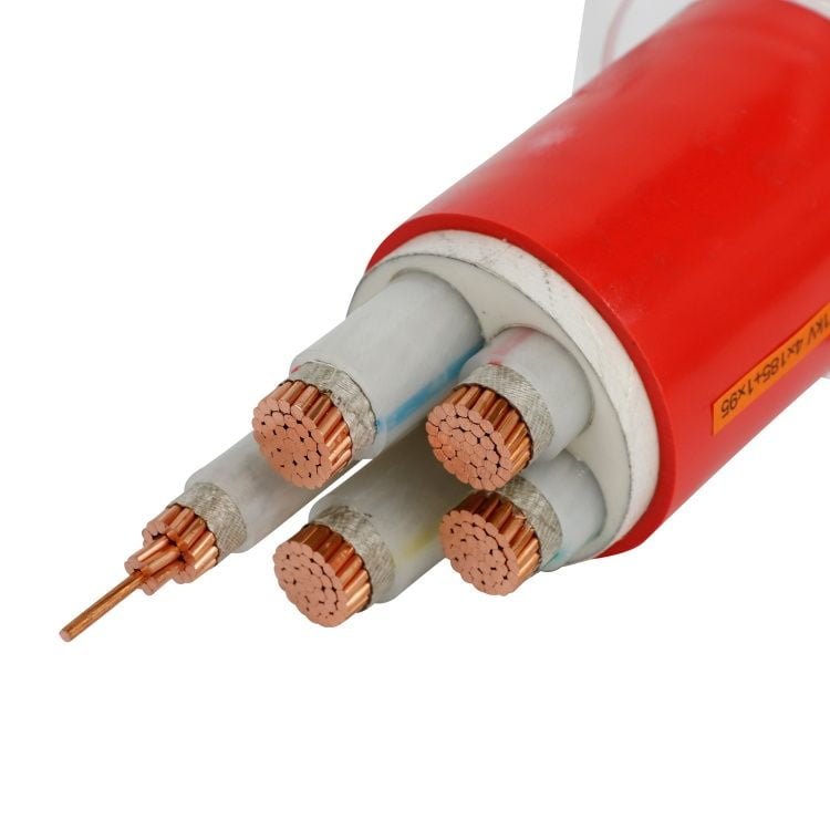
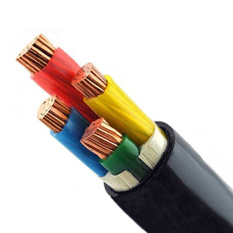
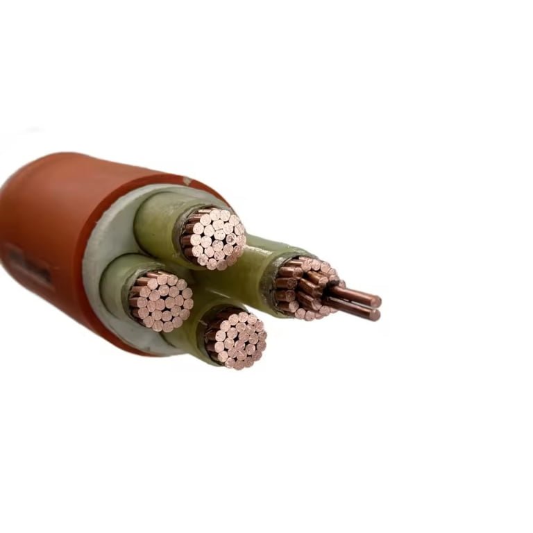
A shock complaint on the floor is not just a safety note in the supervisor’s log; it can mean a damaged cord grip, a wet control pendant, a missing ground, or insulation that has started to fail under load. If the response is guesswork, production stops, electricians chase symptoms, and the plant pays through downtime, injury exposure, rejected equipment, or a retrofit that should have been designed correctly the first time. The useful answer starts with skin impedance, current path, contact condition, and the electrical safety framework behind the installation.
Voltage does not so much “pass” through skin as drive current through the body once skin resistance is overcome. Dry intact skin can resist more than 100,000 ohms, while wet or damaged skin may fall below 1,000 ohms, so hazardous current can occur at far lower voltages in poor conditions.
That is why the same nominal voltage can be harmless in one maintenance task and dangerous in another: sweaty gloves, a nicked finger, metal jewelry, kneeling on damp concrete, or a chest-crossing hand-to-hand path changes the problem completely. The rest of the discussion needs to treat voltage as the starting condition, not the final risk measurement.
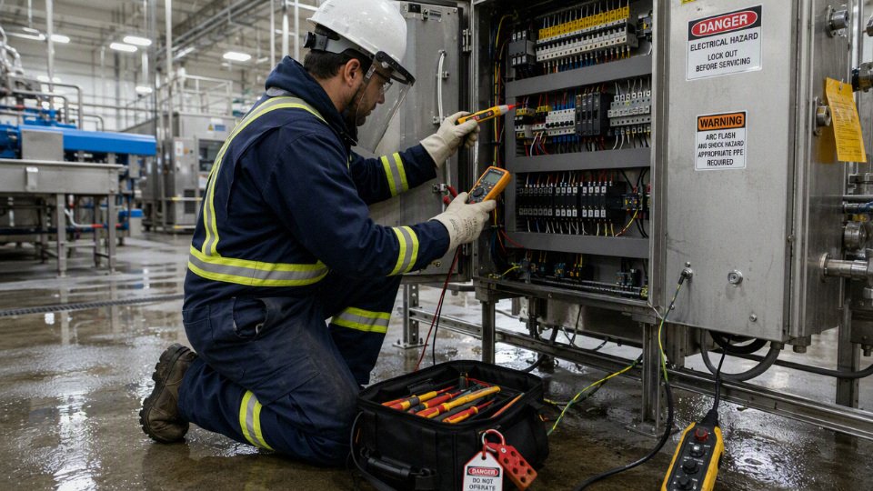
Skin as electrical insulation
Skin is the body’s main electrical barrier only when it is dry, intact, and lightly contacted. Treating it as dependable insulation is a bad plant-floor assumption because the same hand that measures as high resistance at a desk can become a low-impedance contact after sweat, cuts, pressure, wet gloves, metal dust, or a sharp conductor change the interface.
Under normal dry conditions, the outer skin layer, especially the stratum corneum, carries most of the body’s electrical resistance. Once current gets past that layer, the rest of the path is much less resistive. Blood, extracellular fluid, nerves, and muscle contain electrolytes; they are not copper busbars, but compared with dry outer skin they are conductive enough that the entry and exit points often dominate the shock severity.
That is why “body resistance” is a misleading single number. In a shop, the relevant circuit is closer to this:
- Energized conductor or equipment surface.
- Contact interface at the hand, finger, wrist, forearm, or tool.
- Outer skin layer at the entry point.
- Internal tissue path through the body.
- Outer skin layer at the exit point.
- Second contact interface, often a grounded frame, wet floor, ladder, pipe rack, or machine base.
The two skin/contact interfaces can swing the total impedance by orders of magnitude. Dry fingertips brushing a painted enclosure are one situation. A sweaty palm wrapped around a metal pendant station while the other hand rests on a grounded machine column is another.
Skin impedance is not a fixed resistor
Skin behaves as a nonlinear impedance, not a stable resistor from a parts drawer. Its resistance and capacitance shift with voltage, contact pressure, moisture, area, temperature, frequency, and physical damage. If you try to model it with Ohm’s law using one assumed resistance value, you may get a number that is mathematically clean and operationally useless.
Several mechanisms are working at the same time:
- Moisture fills pores, cracks, and surface texture. Sweat and wash water contain ions, so they create conductive bridges through the outer layer and across the contact surface. A summer maintenance shift in a hot motor control room is not the same exposure as a dry office demonstration.
- Pressure increases the effective contact area. A loose brush against a conductor may touch only a few high points. A firm grip flattens skin ridges, squeezes moisture into the interface, and lowers contact impedance.
- Larger contact area can lower resistance. A fingertip contact is not equivalent to a wet palm, a forearm against a panel edge, or a worker kneeling on a damp conductive floor. More parallel microscopic paths become available.
- Higher temperature usually worsens the situation. Warm skin sweats more, softens, and makes better contact. Heat from an arc, overloaded terminal, or hot conductor can also injure the outer barrier.
- Frequency changes the impedance path. At power frequency, 50 Hz or 60 Hz, current interacts strongly with nerves and muscle. At higher frequencies, capacitive effects and surface heating become more relevant, so the hazard analysis must follow the actual source, waveform, and duration rather than a generic “voltage” label.
- Damage bypasses the best insulation layer. Abrasion, cuts, punctures, burns, chemical irritation, dermatitis, and metal splinters all reduce or defeat the outer skin barrier.
In practice, I would not accept a shock-risk argument that says, “Dry skin is 100,000 ohms, so this voltage is safe.” That statement ignores the conditions that usually exist during maintenance: sweat inside gloves, solvent residue, conductive dust, sharp wire ends, scratched knuckles, and a worker leaning into grounded steel to get torque on a fastener.
Dry intact skin versus compromised skin
Dry intact skin can have high impedance, sometimes well above 100,000 ohms under light contact and low voltage. Wet, damaged, or punctured skin can fall below 1,000 ohms. Those values are not universal ratings; they are condition-dependent ranges that show why one person’s mild tingle and another person’s serious shock cannot be explained by voltage alone.
Useful distinctions for electrical work are:
| Skin or contact condition | Electrical effect | Typical plant-floor example |
|---|---|---|
| Dry, intact skin with light contact | Highest resistance condition, though still not a safety control | Brushing a dry knuckle against an insulated tool handle or painted surface |
| Sweaty skin | Lower surface and pore resistance | Working near ovens, extrusion lines, boiler rooms, rooftops, or non-air-conditioned MCC rooms |
| Wet skin | Much lower contact resistance, especially with salts or detergents | Washdown area, cooling tower platform, rain-soaked outdoor cabinet |
| Abraded or cut skin | Outer high-resistance layer partly bypassed | Cable pulling, tray work, sheet-metal edges, stripped conductor strands |
| Burned skin | Barrier damaged; carbonized or blistered tissue can change the path unpredictably | Arc flash exposure, hot terminal contact, overheated lug |
| Chemically contaminated skin | May irritate, hydrate, or ionically contaminate the surface | Alkali cleaners, plating chemicals, battery electrolyte, process salts |
| Punctured skin | Direct path through the outer layer | Needle-like wire strand, sharp test probe, broken shielding braid |
The trade-off is uncomfortable but important: dry skin can reduce current at low voltage, yet relying on that reduction gives a false margin. If the work environment changes from dry commissioning to wet production cleaning, the same exposed voltage can move from barely perceptible to dangerous without any change in the electrical system.
Dry, intact skin can behave as a high-resistance barrier, but wet, damaged, or punctured skin can reduce body impedance by orders of magnitude.True
This matches established electrical safety principles and the supplied impedance range: skin impedance can be below 1,000 ohms in poor contact conditions and above 100,000 ohms when dry and intact. The exact value still requires the actual contact area, voltage, duration, skin condition, and current path.
Higher voltage can break down the barrier
At higher voltage, skin may no longer behave like a passive dry coating. The electric field across the outer layer can cause dielectric breakdown, forcing conductive channels through the skin and sharply reducing resistance. Once that happens, current can rise far above what a low-voltage resistance measurement would predict.
This is one reason insulation testing habits can mislead people if they are casually applied to the human body. Measuring high resistance at a low test voltage does not prove the same barrier will hold at a much higher potential. Skin is biological material: hydrated, uneven, aging, salty, compressed, and often damaged. It does not fail like a clean molded polymer with a neat datasheet rating.
The mechanism is a cascade. Voltage stress concentrates at thin, wet, or damaged spots. Local current heats tissue and changes moisture distribution. That lowers resistance locally, which allows more current, which creates still more heating and injury. The process does not need to be stable or repeatable to be dangerous; it only has to form a better conductive path for a fraction of a second.
The safe engineering position is that skin may reduce current in favorable low-voltage contact conditions, but it must never be treated as part of the protective insulation system. The protective system belongs in the equipment: insulation systems rated for the voltage and environment, bonding conductors, grounding or earthing arrangements, protective relays, fuses or breakers with verified clearing behavior, residual current devices where appropriate, barriers, interlocks, test-before-touch practices, lockout procedures, and trained work methods.
Contact geometry can dominate the result
The electrode matters. A round busbar, a stranded conductor whisker, a sharp test probe, and a broad wet enclosure face do not contact skin the same way.
A small sharp conductor concentrates current density into a tiny area. It may pierce the skin or burn through a contact spot quickly, bypassing the high-resistance surface layer. I have seen stripped fine-strand cable ends behave like little needles; they are mechanically unimpressive but electrically ugly when energized.
A large wet contact patch works differently. It may not puncture the skin, but it creates many parallel conductive paths and lowers the interface resistance. A sweaty palm around a metal handrail, a wet forearm against a stainless washdown cabinet, or a knee on a damp floor can make the body part of a much better circuit than a dry fingertip touch.
This is also why footwear, gloves, mats, and tools must be selected and maintained as equipment, not lucky accessories. A glove with pinholes, carbon tracking, oil contamination, or the wrong voltage class is not “extra skin.” A rubber mat with metal swarf embedded in it, especially near a grinder or cable stripping bench, deserves suspicion. Site safety programs need inspection habits that catch those details before someone becomes the test instrument.
Why a lower voltage can be more lethal than a higher one
A person may survive a brief high-voltage incident on one current path and be killed by a lower voltage on another path. That sounds contradictory until the circuit is drawn properly. Shock outcome depends on current magnitude, path through the body, contact duration, waveform, frequency, and whether the person can release the conductor.
For 50 Hz or 60 Hz AC, perception may begin around 0.5 to 1 mA. Painful shock and loss of muscular control can occur from several milliamps into the tens of milliamps, depending on the person and contact condition. Ventricular fibrillation risk rises with current through the chest and with duration. The exact thresholds and time-current zones should be checked against recognized frameworks such as IEC 60479 and the electrical safety rules used at the site.
A brief hand-to-foot event may cause burns and throw the person clear, while a lower-voltage hand-to-hand contact across the chest can lock muscles and extend exposure. A worker gripping a live conductor with one hand and a grounded enclosure with the other is in a worse cardiac path than someone receiving a surface flash to one limb only. Neither case is acceptable, but the severity ranking is not set by voltage alone.
The boundary on this whole discussion is medical variability and incident complexity. Skin condition explains much of the electrical uncertainty, not all of it. Heart rhythm timing, body size, contact duration, fall hazards, burns, and emergency response all affect the outcome. For design and procurement, that uncertainty argues for engineered prevention, not for trying to calculate how much abuse a person’s skin might tolerate.
Voltage thresholds by condition
Roughly 50 V AC and 120 V DC are widely used extra-low-voltage reference points, but they are not magic safe-contact limits. They assume ordinary conditions, limited exposure, and body impedance that can disappear fast when skin is wet, cut, compressed against metal, or bypassed by a tool, connector pin, probe tip, or damaged insulation.
A voltage below a common extra-low-voltage limit can still be hazardous if skin resistance is low or the energy source can deliver high current.True
Shock severity depends on current path, contact area, duration, source impedance, skin condition, and available energy. Extra-low-voltage limits are engineering thresholds, not universal guarantees of harmless contact.
Practical voltage ranges are condition-dependent, not absolute
A dry fingertip touching a smooth, clean terminal is a very different electrical contact from a sweaty palm wrapped around a spanner. The first case may have skin impedance high enough that current is barely perceptible. The second may put a large contact area, salt water, pressure, and metal in series with the body, dropping skin impedance by orders of magnitude.
The table below is the kind of mental model I use when reviewing panels, battery rooms, welding stations, test benches, or portable equipment. It is not a substitute for IEC 60479, IEC 61140, IEC 60364, NFPA 70E, OSHA requirements, or local code, but it helps stop the common shop-floor mistake of treating voltage labels as personal protection.
| Contact condition | Typical impedance behavior | What voltage means in practice |
|---|---|---|
| Dry, intact skin, light contact | Can be tens of thousands of ohms to more than 100,000 ohms | Lower voltages may not be felt, but perception still varies by person, contact area, and duration. |
| Damp skin or sweaty hands | Skin impedance drops sharply, sometimes into low thousands of ohms | Voltages considered “low” in dry conditions can become noticeable, painful, or involuntary-grip hazards. |
| Wet skin, conductive contamination, rain, washdown | Often below a few thousand ohms; can approach below 1,000 ohms | Even extra-low-voltage circuits deserve respect if current capacity is high or contact is broad. |
| Immersed skin | Skin barrier is heavily compromised over a large area | Voltage thresholds lose much of their practical meaning; current path and source limitation dominate. |
| Broken, abraded, punctured, or burned skin | Protective outer layer is bypassed | Small electrodes, probe tips, wire strands, or cuts can create a much lower-resistance entry point. |
| Metal-tool contact | Pressure and metal contact reduce interface resistance | The tool can bridge terminals, create arcs, heat rapidly, or put current through hand-to-hand or hand-to-arm paths. |
| Internal contact, medical electrodes, invasive contact | Skin is no longer the controlling barrier | Very small currents can matter; this is outside normal industrial “touch voltage” assumptions. |
The mechanism is simple but easily underestimated: the stratum corneum, the dry outer layer of skin, contributes much of the resistance. Moisture, salts, abrasion, pressure, and contact area all reduce that barrier. Once the outer skin is compromised, the body’s internal tissues are comparatively conductive, so current is then governed more by the circuit and path than by the reassuring voltage number on the nameplate.
The practical boundary is this: voltage thresholds are most useful for designing equipment under defined dry-contact assumptions; they are weak as personal safety promises in wet, damaged, confined, conductive, or high-energy situations.
Why 12 V, 24 V, and 48 V systems are safer but not harmless
12 V, 24 V, and 48 V systems are usually safer for accidental touch because they struggle to drive dangerous current through intact dry skin. That is why they are common in control circuits, vehicle systems, communications equipment, solar balance-of-system hardware, sensors, LED lighting, access controls, and battery-backed panels. The trade-off is that lower voltage often means higher current for the same power, so conductors, terminals, fuses, and battery fault energy become the real hazard.
A 24 V control cabinet with a modest power supply is one thing. A 48 V lithium battery rack, telecom rectifier, forklift battery, or solar string combiner is another. The touch shock may be less severe than mains under many conditions, but the source can dump enough current to melt a ring, vaporize a screwdriver tip, or start a terminal fire before a slow protective device clears.
Typical low-voltage hazards that get missed in procurement reviews include:
- Short-circuit current from batteries: Batteries do not behave like small control transformers. A lead-acid or lithium pack can deliver very high fault current until a fuse, BMS, contactor, or conductor fails.
- DC arcing: DC arcs do not naturally cross zero like AC arcs. Switches, relays, and breakers must be DC-rated for the voltage and prospective current.
- Burns from jewelry and tools: A wedding ring across a 24 V or 48 V bus can become a heating element. I have seen maintenance teams remove rings only after the first near miss; it is a bad policy to learn that way.
- Wet-location shock risk: Irrigation controls, washdown machinery, outdoor lighting, and vehicle service pits can turn “only 24 V” into a condition that deserves enclosure, bonding, insulation, and current-limiting attention.
- Stored energy in capacitors: Drives, chargers, UPS equipment, and LED power systems may retain hazardous energy after disconnect unless properly discharged and verified.
There is also a commercial trap here. Buyers sometimes specify 24 V controls to make a machine “safe,” then allow undersized terminal blocks, poor strain relief, unprotected battery leads, or mixed AC/DC wiring in the same trough. The safer voltage class helps, but it does not replace short-circuit protection, segregation, insulation coordination, proper cable sizing, and documented lockout practice.
110 V to 120 V AC versus 220 V to 240 V AC mains
Both 110 V to 120 V AC and 220 V to 240 V AC mains can pass dangerous current through skin. The higher-voltage system generally has more margin to force current through imperfect contact, but either range can exceed perception, let-go, and fibrillation-related current levels depending on body path, duration, grounding, and source impedance.
At 50 Hz or 60 Hz, perception often starts around 0.5 to 1 mA. Pain, involuntary muscle reaction, and loss of muscular control can occur in the several mA to tens of mA range, while ventricular fibrillation risk depends heavily on current magnitude, path through the chest, and exposure time. These are not procurement-friendly fixed numbers because body impedance can move from more than 100,000 ohms in dry, intact contact to below 1,000 ohms when wet, damaged, or punctured.
A simple Ohm’s law sketch shows why the same voltage label can mislead:
- Dry fingertip, high impedance: current may be limited enough that the contact is only felt or not felt.
- Sweaty hand gripping a grounded frame: current can rise sharply, especially with broad contact area.
- Hand-to-hand contact across the chest: the path is more dangerous than finger-to-elbow because heart exposure is higher.
- Standing on a wet floor in worn boots: contact path through legs and footwear may be much lower than assumed during design.
- Metal probe slip inside an energized cabinet: skin may not be the only interface; the event may become an arc or burn incident as much as a shock event.
In practice, 120 V systems are sometimes treated casually because many electricians and mechanics have been shocked and “walked it off.” That experience is a poor risk model. A startle fall from a ladder, a clenched hand on a live conductor, or a shock through the torso in a humid pit can turn a familiar voltage into a fatal event. 230 V systems, common across much of the world, deserve the same discipline plus the recognition that the voltage has less tolerance for poor contact assumptions.
Protective devices change the outcome but do not make contact acceptable. RCDs, GFCIs, fuses, breakers, isolation transformers, bonding, and double insulation all address different failure modes. A breaker sized to protect cable from overheating may not trip fast enough to protect a person from shock. A residual-current device may save a life in a line-to-ground event but may not respond to every line-to-neutral contact or every DC leakage condition, depending on device type.

Medium-voltage and high-voltage systems are not just “more shock”
Above low-voltage distribution, the hazard changes character. Medium-voltage and high-voltage equipment can injure without ordinary hand contact because air insulation can break down, arcs can form, and step or touch potentials can develop around faults. At that point, the question is no longer “what voltage can skin withstand?” but “what approach distance, insulation system, grounding design, arc energy, and switching procedure controls the exposure?”
Several mechanisms matter:
- Flashover: Voltage can bridge an air gap if clearance, contamination, humidity, altitude, or transient overvoltage allows breakdown.
- Arc flash: A fault can produce intense heat, pressure, molten metal, and light. Skin burns may occur without current passing through the body in the usual shock sense.
- Step potential: During a ground fault, voltage gradients can exist across the floor or soil. A person’s feet may span enough voltage to drive current through the legs.
- Touch potential: A grounded-looking fence, cabinet, cable sheath, or structure can rise above true earth during a fault.
- Tracking and contamination: Dust, salt fog, moisture, and carbonized insulation can create conductive paths across surfaces that looked acceptable when new.
This is why utility rooms, substations, large drives, wind and solar collection systems, test labs, and heavy industrial switchgear require procedures that include boundaries, verified isolation, grounding, rated PPE, remote operation where appropriate, and equipment-specific switching instructions. A pair of leather gloves and confidence are not controls.
AC, DC, and frequency change the injury pattern
Power-frequency AC at 50 Hz or 60 Hz is especially concerning because it interacts strongly with muscles and the heart’s electrical timing. It can cause tetany, where the hand cannot release, and it is associated with ventricular fibrillation risk at currents that may not look dramatic from a power-system perspective. The same contact that makes a person jump with DC may lock them on with AC.
DC contact behaves differently. It often causes a single strong contraction at make or break, can create deep burns at contact points, and at higher current can still prevent voluntary release or cause severe injury. DC also brings equipment hazards that maintenance teams sometimes underestimate: persistent arcs, polarity-sensitive protective devices, electrolytic corrosion paths, and capacitors that remain charged after the upstream disconnect is opened.
Frequency is the last piece that should keep engineers from using one universal threshold. Very high-frequency current tends to travel differently through tissue and is generally less likely than 50 Hz or 60 Hz current to trigger fibrillation at the same measured current, but high-frequency energy can still burn tissue severely. RF heating, induction heating, dielectric heating, and some welding or test equipment can damage skin and deeper tissue while the sensation does not match the severity.
So voltage thresholds should be used as design tools, not permission slips. For actual equipment selection or safety review, the defensible inputs are the supply type, available fault current, protective device behavior, grounding system, environment, contact scenario, exposure duration, and maintenance practice. The voltage number is only the first line on the worksheet, not the decision.
Current paths through the body
The same nominal voltage can produce very different injury outcomes depending on where the current enters and leaves the body. A path that crosses the chest deserves much more concern than a small localized contact on one finger, because the heart, lungs, and major muscle groups are in the circuit. In electrical safety work, the body route is often as important as the voltage number on the nameplate.
Common contact paths and why they are not equal
On a plant floor, shock paths are rarely clean textbook cases. A mechanic may have one hand on a motor frame and the other on a gland plate. An operator may lean against a stainless control panel while touching a wet pushbutton station. A cable jointer may be kneeling on damp ground with one forearm against a tray. The route is set by the points of contact, footwear, gloves, sweat, cuts, tools, and whatever bonded metal happens to be nearby.
The main body paths to think about are:
| Contact path | Typical industrial scenario | Relative concern |
|---|---|---|
| Hand-to-hand | One hand touches a live conductor while the other holds a grounded enclosure, tray, pipe, or machine frame | High, because current can cross the chest |
| Hand-to-foot | A hand contacts an energized part while current returns through legs, boots, floor, rebar, or earth | High, especially on wet floors or conductive grating |
| Foot-to-foot | A person stands across a voltage gradient near a ground fault, downed conductor, lightning strike, or substation grid | Variable, but serious at high ground-potential rise |
| Hand-to-elbow or hand-to-forearm | Local contact while reaching into a panel or handling damaged cable | Usually less chest involvement, but burns and muscle contraction can still be severe |
| Head-to-hand | Head or face contacts one point while a hand contacts another, seen in cramped cable vaults, machinery, or overhead work | High concern due to current near the head, neck, and chest |
| Localized finger contact | One finger bridges two terminals or touches a small exposed part | Often localized, but not automatically safe; punctures and burns can lower skin impedance fast |
Hand-to-hand and hand-to-foot are the classic high-concern paths because they can put the heart in the current route. That is why industrial procedures try to avoid two-handed probing in live panels and why the “one hand in the pocket” habit still gets taught by old electricians, even though it is not a substitute for proper isolation, verification, and PPE. It reduces one possible chest-crossing route; it does not make live work safe.
There is a mechanism behind the difference. Current density is not uniform through the body. The entry and exit points, tissue conductivity, contact area, and internal organs in the route shape where energy is deposited. Skin may take much of the voltage drop at first if it is dry and intact, but once sweating, arcing, puncture, or prolonged contact reduces that barrier, deeper tissue can carry more current. A small fingertip arc may produce a nasty burn without much whole-body current, while a damp palm-to-foot contact at a lower voltage can involve more of the torso.
Foot-to-foot shock and step potential
Foot-to-foot current is easy to underestimate because the person may not touch the equipment at all. During a ground fault, lightning event, downed overhead conductor, or substation earth-grid rise, the soil or floor can have a voltage gradient. If the two feet are at different potentials, current can pass up one leg and down the other.
This is the step-potential problem. It shows up around:
- Substation fences, ground grids, and transformer yards during faults.
- Downed conductors, especially on wet soil, asphalt edges, or drainage paths.
- Mobile equipment contacting overhead lines.
- Lightning strikes near outdoor structures, tanks, fences, or buried services.
- Temporary generation and construction power where grounding is improvised or poorly tested.
- Large fault currents returning through building steel, cable armor, conduit, or earth electrodes.
Foot-to-foot current is less likely than hand-to-hand current to pass directly through the heart, but that does not make it benign. High ground-potential gradients can drive enough current to cause leg muscle contraction, falls, burns at the feet, or secondary injury. If the person falls and catches a fence, vehicle, cabinet, or cable with a hand, the path may immediately become hand-to-foot or hand-to-hand, which is worse.
This is why substation and utility crews are trained to keep feet together and shuffle or hop away from a suspected energized zone. In factories, the parallel lesson is equipotential bonding: if personnel can bridge two conductive objects, those objects should not sit at meaningfully different potentials during normal operation or a credible fault. Cable trays, machine frames, skid bases, piping, local panels, and structural steel need bonding that is designed, installed, inspected, and maintained—not just assumed because “everything is bolted down.”
Contact duration changes the injury mechanism
A brief startle shock is not the same event as being unable to let go. Duration matters because the body is not just a resistor; muscles, nerves, skin, and organs respond over time. At 50 Hz or 60 Hz, alternating current can repeatedly stimulate nerves and muscles, and certain current-time combinations are associated with higher ventricular fibrillation risk under recognized frameworks such as IEC 60479.
Approximate physiological effects are best treated as ranges, not design limits:
| Approximate current through the body | Possible effect at 50 Hz or 60 Hz AC | Practical caution |
|---|---|---|
| Around 0.5 to 1 mA | Perception, tingling | Varies strongly by person, contact area, moisture, and path |
| Several mA | Pain, startle reaction, hand withdrawal | Startle can cause falls, tool drops, or contact with rotating machinery |
| Roughly 5 to 20 mA, give or take | Involuntary muscle contraction; “can’t let go” becomes possible for some people | Let-go thresholds vary; do not use a single value as safe/unsafe |
| Tens of mA | Strong contraction, breathing difficulty, respiratory interference | Chest-crossing paths become especially concerning |
| Tens to hundreds of mA, depending on time and path | Increased ventricular fibrillation risk | Current duration and timing in the heart cycle matter |
| Higher currents or arcing contacts | Burns, deep tissue injury, nerve damage, blast or arc-related trauma | Protective clearing and available fault energy dominate outcome |
A fast protective device can reduce duration, but only if the fault current is high enough and the circuit arrangement allows the device to see the fault. This is where procurement and maintenance decisions become safety decisions. A low-impedance bolted fault may trip a breaker quickly; a high-impedance leakage path through a wet glove, carbonized insulation, or a human body may not. Residual-current devices, ground-fault protection, insulation monitoring, bonding conductors, and correct breaker coordination all exist because overcurrent protection alone does not cover every shock scenario.
The trade-off is familiar to anyone who has commissioned equipment in mixed old-and-new plants. Sensitive ground-fault protection improves personnel protection and fault detection, but it can nuisance-trip on long cable runs, VFD filters, heater moisture leakage, or accumulated capacitive leakage if the system is not engineered properly. Loosening protection to keep production running may hide a deteriorating insulation problem until someone becomes the return path. The preferred choice flips only after the leakage sources are understood, the protective scheme is coordinated, and the operating risk is assessed against applicable electrical safety rules—not because operators are tired of resetting a breaker.
Voltage marking is only part of the incident
A 24 V control circuit, a 120 V receptacle, a 230 V machine supply, and a medium-voltage cable termination are obviously not the same hazard class. Still, the marking alone does not tell the whole story. Shock severity depends on:
- Available fault current from the source.
- Source impedance, transformer size, generator characteristics, and cable length.
- Grounding arrangement and return path quality.
- Body contact resistance at that moment: dry, wet, sweaty, cut, gloved, or punctured.
- Contact area and pressure.
- Current path through the body.
- Protective-device type and clearing time.
- Whether the person is trapped, gripping, kneeling, elevated, or standing in water.
- Presence of parallel conductive structures such as pipe racks, cable trays, machine frames, and rebar.
Where personnel may bridge two conductive points, touch-voltage control and equipotential bonding are not optional finishing details; they are core parts of shock-risk reduction. The boundary of this conclusion is not that bonding eliminates all shock hazards. It reduces dangerous potential differences between accessible conductive parts when it is continuous, correctly sized, protected against corrosion and mechanical damage, and verified under the fault conditions the installation can actually produce.
Industrial touch-voltage hazards
In industrial work, touch voltage is the voltage a person can bridge between two conductive points: a machine frame and ground, two pieces of metalwork, a cable sheath and a wet floor, or an energized conductor and a ladder. The dangerous part is not the voltage label alone; it is the fault condition, contact surface, body path, moisture, and disconnection time that decide how much current flows.
A clean electrical drawing may show a single fault path. The plant floor rarely behaves that politely. Cable trays become bonding paths, stainless washdown frames stay damp, temporary panels sit on muddy ground, and a worker with sweaty hands may contact an enclosure while leaning against a pipe rack. That is where the skin-voltage discussion becomes a procurement and installation problem, not only a medical one.
Where touch voltage appears in industrial installations
Touch voltage can exist during normal operation if exposed conductive parts are intentionally energized, poorly isolated, or capacitively coupled. More commonly, it appears during a fault: insulation breaks down, a conductor contacts a frame, the protective earth path is weak, and the metalwork rises above local ground until protection clears the fault.
Typical contact combinations include:
- Machine frame to floor or structural steel, especially where earthing is missing, corroded, or cut during maintenance.
- Cable armor or metallic sheath to handrail, tray, pipe, or enclosure, usually after termination errors or insulation damage.
- Portable tool body to wet concrete, common with worn flexible cords and temporary distribution boards.
- Two conductive surfaces at different potentials, such as separate skid packages, generators, shore-power connections, or mobile equipment parked near fixed installations.
- Solar array frames, wind tower internals, rail equipment, and substation fencing, where long cable runs and grounding networks can create step-and-touch exposure during faults.
The mechanism is straightforward but unforgiving. A fault current needs a return path. If the intended protective path has low impedance, the current is high enough to operate a breaker, fuse, residual current device, or protection relay quickly. If the protective path is loose, undersized, corroded, incorrectly bonded, or simply absent, the exposed metal may sit at a hazardous voltage for longer while the human body becomes part of the parallel path.
Cable-related failure modes that create touch-voltage exposure
Cables are often treated as passive commodities after installation, but they are one of the main barriers between workers and energized conductors. In my experience, many touch-voltage incidents start as ordinary cable abuse that nobody budgeted to prevent.
The common failure modes are not all the same:
- Insulation damage: Cuts, crush points, overbending, and thermal overload can reduce dielectric strength until a conductor leaks or faults to armor, tray, or equipment frame.
- Sheath cracking: UV exposure, cold bending, chemical attack, and age can split the outer jacket, letting moisture and contamination reach layers that were never meant to be exposed.
- Water ingress: Capillary action through damaged jackets, poor gland sealing, or open cable ends can track water along conductors and shields. Once water and dirt enter, insulation resistance can fall in a way that looks intermittent rather than obvious.
- Conductor exposure: Abraded jackets on portable leads, hoist cables, drag chains, and festoon systems create direct contact risk, especially where workers grab the cable to move it.
- Termination defects: Stray strands, wrong strip length, nicked insulation, inadequate creepage distance, and poor stress control at medium-voltage terminations can put voltage where the installer never intended it.
- Poor crimping: Under-crimping leaves high resistance and heat; over-crimping can cut strands. Both can lead to hot spots, loosening, insulation damage, and eventual faulting.
- Incorrect gland selection: A gland that does not match cable diameter, armor type, sealing requirement, or hazardous-area rating can fail mechanically or electrically. I have seen good cable made unsafe by a cheap gland and a missing locknut.
- Jacket abrasion: Cable rubbing against tray edges, conveyor frames, forklift routes, or unbushed knockouts slowly removes the outer layer. Abrasion is boring until the day it is not.
- Rodent damage: Tunnels, warehouses, farms, solar sites, and port facilities are especially vulnerable. Rodents do not respect cable schedules.
- Thermal aging: Heat from overload, ambient temperature, grouping, sunlight, nearby process equipment, or harmonic current hardens insulation and reduces remaining life.
Damaged portable cords and flexible cables deserve special attention because workers handle them directly, repeatedly, and often in wet or dirty conditions. A fixed feeder inside tray may fail dangerously, but a worn extension lead on a construction floor puts the worker’s hand inches from the defect. Low-cost flexible cable can be tempting on a purchase order, yet soft jackets, marginal copper, weak strain relief, and poor abrasion resistance turn into frequent replacement, nuisance repairs, and higher handling exposure.
A 24 V or 48 V industrial circuit is always safe to touch.False
Low nominal voltage reduces shock risk, but wet skin, damaged skin, conductive slurry, long contact duration, stored energy, or faulted equipment can still create hazardous exposure. Safety decisions need the actual circuit, environment, contact condition, and applicable standards, not only the nameplate voltage.
Environments that make skin and contact resistance worse
The same voltage that is merely uncomfortable in a clean, dry panel shop can become dangerous in a wet tunnel or salt-covered port crane. Moisture lowers skin impedance, increases contact area, and helps contamination form conductive films across insulation surfaces. Conductive dust does something similar, especially carbon, metal fines, cement dust with moisture, and mining dust mixed with process water.
High-risk industrial settings include:
| Environment | Why touch-voltage risk increases |
|---|---|
| Factories | Oil, coolant, washdown water, metal chips, cable movement, and crowded equipment bases create many contact points. |
| Mining sites | Wet ground, conductive slurry, trailing cables, vibration, and mechanical abuse are routine, not exceptions. |
| Ports and shipyards | Salt spray, shore power, cranes, steel decks, welding leads, and damaged flexible cables are a rough combination. |
| Tunnels and rail systems | Confined metal structures, water seepage, long cable runs, and limited escape space raise consequence. |
| Substations | High fault energy, transferred potentials, step voltage, and touch voltage around fences and structures require engineered grounding. |
| Solar farms | UV exposure, rodents, DC circuits, long strings, and wet vegetation complicate inspection and fault detection. |
| Wind farms | Tower condensation, vibration, nacelle movement, lightning exposure, and cramped workspaces affect both cables and workers. |
| Data centers | High power density, underfloor cabling, battery systems, and maintenance under uptime pressure create different but serious exposure. |
| Oil and gas sites | Chemicals, hydrocarbons, hazardous-area equipment, corrosion, and remote maintenance raise the cost of small mistakes. |
| Temporary construction power | Repeated relocation, rough handling, mud, rain, improvised supports, and mixed subcontractor ownership are classic failure drivers. |
Cramped spaces make the risk worse because the worker cannot avoid simultaneous contact. A technician inside a wind tower, a miner handling a trailing cable, or an electrician kneeling in front of a damp pump skid may contact grounded metal with knees, elbows, shoulder, or tools. Sweating under gloves lowers resistance too; anyone who has worked an August shutdown in a compressor room knows the difference between a dry inspection and a soaked one.
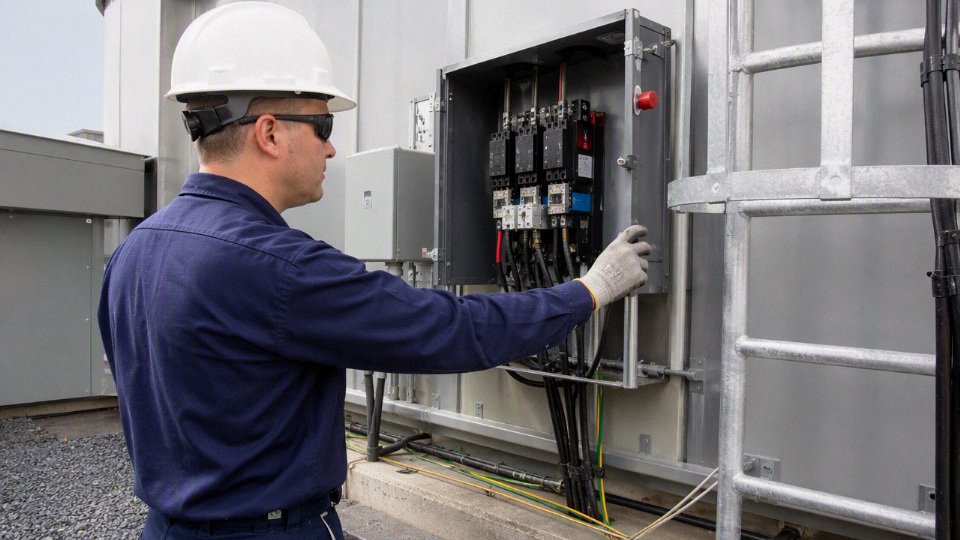
Protective design measures that actually reduce exposure
Protective design is layered because no single measure catches every failure. Good insulation helps until it is damaged. Earthing helps if the fault path remains intact. RCDs help within their rating and application limits, but they are not a substitute for correct cable routing, bonding, and maintenance.
A practical touch-voltage control plan should cover:
- Insulation coordination: Match insulation level, creepage, clearance, surge exposure, pollution degree, and installation category to the system. This is especially important around drives, long motor cables, solar DC, and substations.
- Correct voltage rating: Cable voltage rating must suit the nominal system, transients, earthing arrangement, and application. Do not buy a cable only by conductor size.
- Protective earthing and bonding: Exposed conductive parts, cable armor, trays, skids, frames, and enclosures need a verified low-impedance path back to the source or grounding system.
- Residual current protection: RCDs, GFCIs, or equivalent residual-current devices are valuable for socket circuits, temporary power, wet areas, and portable equipment, subject to coordination and local code.
- Insulation monitoring: In IT systems, mining systems, ships, medical-type isolated systems, and selected DC networks, insulation monitoring can warn before the second fault creates a severe hazard.
- Overcurrent protection: Breakers and fuses must clear faults within required times. That depends on available fault current, device curves, cable impedance, and installation method.
- Fault-loop impedance control: The loop must be low enough for protective devices to operate. Long runs, undersized protective conductors, loose terminations, and corroded joints can defeat the design.
- Lockout and tagout: De-energization, isolation, test-before-touch, stored-energy discharge, and controlled re-energization remain essential during maintenance.
- Barriers and guarding: Covers, gland plates, cable covers, tray lids, fencing, insulating mats, and restricted-access zones reduce accidental contact.
- Warning and indication systems: Voltage indicators, ground-fault alarms, signage, beacon alarms, and interlocks help, provided workers trust them because nuisance alarms have been addressed.
There is a trade-off in protection settings. More sensitive residual-current protection can reduce shock duration, but in large drives, long cable runs, wet sites, or EMC-filtered equipment it may nuisance trip unless the system is designed for it. If nuisance trips stop production, maintenance crews start bypassing protection; that is usually worse than choosing a properly coordinated device and fixing leakage at the source.
Industrial shock-risk decisions should be checked against recognized frameworks such as IEC 60479 for current effects on humans, IEC 61140 for protection against electric shock, IEC 60364 for low-voltage installations, NFPA 70E for electrical safe work practices, OSHA requirements, and the applicable local electrical code. Those documents do not remove the need for measurement; they tell you how to judge the installation once you know the circuit, clearing time, grounding arrangement, and exposure condition.
Why procurement choices change shock risk
Cable purchasing affects shock risk long before an electrician pulls the first meter off a drum. Conductor quality affects heating and termination reliability. Insulation material affects dielectric strength, temperature life, chemical resistance, and behavior under overload. Jacket durability decides whether the cable survives oil, sunlight, abrasion, mud, salt, or repeated flexing.
For technical buyers, the decision should not stop at “same size, lower price.” Specify and verify:
- Conductor material and construction: copper or aluminum, class of stranding, flexibility, strand quality, and compatibility with lugs and terminals.
- Insulation compound: PVC, XLPE, rubber, EPR, silicone, fluoropolymer, or other material selected for voltage, heat, chemicals, and flexibility.
- Outer jacket performance: abrasion, oil resistance, UV resistance, water resistance, low-temperature flexibility, and tear strength.
- Mechanical protection: armor, braid, screened construction, drag-chain rating, crush protection, or extra sheath where the route demands it.
- Flame and smoke performance: suited to tunnels, ships, data centers, public infrastructure, or enclosed escape routes where required.
- Certification and compliance: matching the destination market, project specification, and inspection authority rather than relying on a generic datasheet.
- Manufacturing quality control: dimensional consistency, insulation concentricity, routine electrical testing, traceability, and batch documentation.
The boundary is clear: a better cable cannot compensate for bad installation, missing bonding, or ignored maintenance. But poor cable selection can make even a well-designed system fragile, especially in flexible, wet, corrosive, or mechanically exposed applications. For industrial touch voltage, the safer project is usually the one where cable specification, installation method, protection design, and inspection practice are treated as one system rather than four separate purchasing lines.
Cable insulation and protection choices
Cable selection reduces shock risk when the construction is matched to the fault energy, installation abuse, earthing system, and environment—not just the printed nominal voltage. A cable that is “rated for the voltage” can still create dangerous touch voltage if its sheath cracks on a reel, its screen is poorly bonded, or its insulation system is unsuitable for heat, oil, water, UV, or transient stress.
Voltage rating is a system decision, not a nameplate shortcut
Procurement teams often compare cable by rated voltage first, which is reasonable, but it is not enough. The useful question is whether the insulation system can withstand the actual electrical stress it will see over years of service, including normal operating voltage, fault conditions, switching surges, harmonics, moisture ingress, and the way the neutral or earth system behaves during a fault.
For low-voltage power distribution, the difference between a properly selected 450/750 V flexible cord, a 0.6/1 kV power cable, and a control cable pressed into power duty is not academic. The insulation thickness, test voltage, sheath toughness, conductor class, and marking requirements are different. In a dry, fixed cable tray, that margin may never be noticed. On a pump skid that gets washed down every shift, the wrong construction usually announces itself as nuisance tripping first, then insulation tracking, then a dangerous exposed-conductor or earth-fault event.
For medium-voltage cable, the selection becomes less forgiving. System voltage, highest system voltage, impulse withstand level, conductor screen, insulation screen, metallic screen rating, and partial discharge performance all matter. Transient overvoltage category and earthing arrangement change the stress profile: an effectively earthed system behaves differently from an unearthed or impedance-earthed system during a single line-to-earth fault. A cable that survives normal phase-to-phase operation may be overstressed if the system allows extended earth-fault operation.
The practical buying rule is simple: specify cable against the full electrical system and installation duty, not only against the voltage printed on the switchgear. That means the enquiry should state:
- Nominal voltage and highest system voltage
- AC frequency, DC service, or variable-frequency drive duty if relevant
- Earthing arrangement and expected earth-fault clearing time
- Installation method: tray, duct, direct burial, tunnel, reel, festoon, submerged, open air
- Ambient temperature, conductor operating temperature, solar exposure, and grouping
- Chemical exposure: oils, fuels, acids, alkalis, solvents, slurry, seawater
- Mechanical duty: fixed, flexing, torsion, abrasion, crushing, pulling tension
- Fire performance requirement and smoke/toxicity limits
- Applicable market standards and project specifications
The conclusion has a boundary: no catalogue rating can replace the coordination study and installation design. Cable insulation helps prevent hazardous contact, but protective devices, earthing conductors, bonding, enclosures, glands, and installation workmanship decide how quickly a fault becomes safe.
Insulation and sheath families at planning level
Different cable compounds fail in different ways. That is why experienced buyers do not ask only “PVC or XLPE?” They ask what the cable will be exposed to at 2 a.m. when a fitter drags it across a steel edge, a gland seal loosens, or hydraulic oil runs down a cable ladder.
| Material or construction | Where it is commonly considered | Main strengths | Watch points |
|---|---|---|---|
| PVC insulation or sheath | General low-voltage building, control, and industrial wiring | Economical, widely available, easy to process, decent general-purpose performance | Can harden in cold, soften with heat, may not suit oils, UV, or low-smoke requirements unless specially formulated |
| XLPE insulation | Low- and medium-voltage power cables | Higher thermal rating than typical PVC, good dielectric strength, good moisture resistance when correctly manufactured | Less flexible than rubber types; terminations and bending radius must be respected |
| EPR insulation | Flexible power, mining, marine, medium-voltage applications | Good flexibility, good wet electrical behavior, often strong for demanding service | Usually higher cost; compound quality and cure control matter |
| Rubber compounds | Welding leads, trailing cables, mobile equipment, portable power | Flexibility, impact tolerance, abrasion resistance depending on grade | Not all rubber is oil-resistant, heat-resistant, or UV-resistant; exact compound must be specified |
| Halogen-free flame-retardant materials | Public buildings, tunnels, rail, offshore, enclosed industrial spaces | Reduced corrosive/acid gas and smoke behavior compared with halogenated materials, depending on standard | Can be less forgiving mechanically if the wrong grade is selected; fire rating must match the actual standard |
| Specialty oil-, UV-, cold-, or fire-resistant constructions | Refineries, ports, cranes, cold storage, solar, emergency circuits | Targets a known exposure instead of relying on general-purpose cable | Needs clear test basis; vague words like “weatherproof” are not enough |
The mechanism is straightforward: insulation prevents current flow under normal stress, while the outer sheath buys time against the plant environment. If the sheath cracks, absorbs oil, degrades under UV, or wears through on a sharp tray edge, the insulation layer starts living in conditions it was not designed for. Moisture and contamination lower surface resistance, local electric stress rises at cuts or voids, and leakage current can become tracking, flashover, or an earth fault.
There is always a trade-off. XLPE power cable is often a better fixed-installation choice where thermal rating and dielectric performance matter, but it is not the first answer for a constantly flexing hoist pendant or welding lead. Rubber or EPR constructions can take movement better, but they cost more and must be checked for oil, ozone, and flame behavior. Halogen-free flame-retardant cable may be the right call in a tunnel or occupied building, while a rugged oil-resistant sheath may matter more beside a hydraulic press.
Screens, shields, armor, and earth conductors control where fault current goes
Shock prevention is partly about keeping voltage away from people, and partly about giving fault current a low-impedance path that trips protection before a person becomes the path. This is where screens, shields, armor, concentric conductors, and protective earth conductors earn their keep.
Common protective and field-control elements include:
- Conductor screen: A semiconductive layer used in medium-voltage cable to smooth electric stress around the conductor. It prevents high-stress points caused by conductor stranding geometry.
- Insulation screen: A semiconductive layer over the insulation that creates a controlled electrical boundary. It helps avoid partial discharge and uneven stress in MV systems.
- Metallic screen or shield: Copper tape, copper wire screen, or similar metallic layer that can carry charging current and earth-fault current, depending on design. It also gives a controlled touch-potential reference when correctly bonded.
- Armor: Steel wire, steel tape, aluminum wire, or other mechanical protection. Armor may also serve as a protective conductor in some systems if correctly sized and terminated, but that must be verified by design.
- Concentric conductor: Conductors laid around the insulation or core assembly, often used for neutral or earth functions in some cable types.
- Separate protective earth conductor: A dedicated PE core or external earthing conductor that provides the intended fault-return path.
Poor termination defeats good cable construction. I have seen expensive armored cable installed with painted gland plates, loose banjo washers, and no reliable earth continuity across the gland. On paper, the cable had a fault path. In the panel, the fault path depended on corrosion, paint scratches, and luck.
For touch-voltage control, the protective path has to carry enough current for long enough to operate the upstream device, without leaving accessible metalwork at a dangerous potential for too long. The acceptable design depends on local code, protective device type, disconnection time, prospective fault current, and bonding layout. IEC 60364, IEC 61140, NFPA 70E, OSHA requirements, and local electrical codes should be treated as design references, not decorative specification text.
Flexible cables need a different buying mindset
Flexible cable failures are rarely caused by voltage stress alone. They usually start mechanically: repeated bending, torsion, abrasion, crushed jackets, poor strain relief, or someone using a cable as a pulling rope because the shift is behind schedule.
Moving-duty applications need cable selected for the motion pattern:
- Cranes and hoists: Check tensile load, festoon spacing, pendant flexibility, torsion, and outdoor UV exposure. A cable that survives in a tray may corkscrew or core-break on a hoist.
- Cable reels: Specify reeling duty, drum diameter, winding tension, travel speed, and whether the cable is energized while wound. Heat buildup on a loaded reel is a common blind spot.
- Mining and tunneling machinery: Look at abrasion, tear resistance, water, mud, impact, grounding conductors, monitoring cores, and flame requirements.
- Welding equipment: Flexibility and heat resistance matter, but oil, slag, cuts, and temporary routing across walkways matter just as much.
- Submersible and pump cables: Water-blocking, sheath compatibility, gland sealing, and conductor corrosion protection become part of electrical safety.
- Temporary power: Choose cable and connectors as a system. Temporary does not mean light duty; in many plants it gets the worst abuse.
A useful maintenance habit is to inspect flexible leads where they enter glands, plugs, reels, and strain reliefs—not just along the easy visible span. That is where copper work-hardens, jackets split, and moisture enters. Seasonal effects show up too: a cable that feels acceptable in summer can become stiff and crack-prone in a cold yard.
Standards, certification, and factory QA are part of the safety margin
Standards should be specified by market and application, not copied from an old tender. IEC, BS, VDE, UL, CSA, and AS/NZS systems do not always use identical constructions, markings, test methods, or certification routes. A cable acceptable for one export market may not satisfy the inspector, insurer, utility, or mine authority in another.
Factory quality assurance is where many “compliant-looking” cables separate from dependable ones. Relevant checks may include:
- Conductor resistance testing to verify metal cross-section and conductivity
- Insulation resistance testing to detect gross insulation defects or contamination
- High-voltage withstand testing to prove dielectric integrity under specified test conditions
- Partial discharge testing for medium-voltage cable, especially where insulation system quality is critical
- Spark testing on insulation or sheath during production, depending on cable type
- Dimensional inspection for insulation thickness, eccentricity, sheath thickness, and overall diameter
- Flame testing where the construction is sold for flame-retardant or fire-performance duty
- Material traceability for conductor, insulation compound, sheath compound, tapes, screens, and armor materials
The advanced procurement risk is not usually a cable that is openly non-compliant. The bigger danger is the cheapest cable that appears compliant in a quotation table but carries weak process control: thin spots in insulation, recycled or contaminated compound, poor sheath toughness, inconsistent screen application, missing test records, or documentation that cannot be tied back to production batches. Those weaknesses may not show during receiving inspection, yet they raise the chance of nuisance trips, early replacement, arc damage, and touch-voltage exposure later.
Shandong Jinda Special Cable Group Co., Ltd. is positioned for this kind of engineered buying process because its stated capability covers integrated R&D, production, testing, technical support, and after-sales service, with manufacturing scale and export experience for international projects. That does not remove the buyer’s duty to specify the system correctly, but it does give engineering and procurement teams a supplier route for aligning cable construction, test documentation, and operating risk before the order is placed.
Field testing and maintenance controls
Dangerous touch voltage is controlled by proving three things before and after energization: live conductors are where they should be, protective conductors remain low-impedance, and insulation or enclosures have not let voltage reach accessible metalwork. A cable system that passed commissioning can still become unsafe after moisture, heat, vibration, rodent damage, gland movement, or overloaded terminals have had time to work on it. Field testing is not paperwork; it is how you catch that drift before a person becomes the fault path.
Pre-energization checks before power is applied
On a new installation, the cheapest time to find a shock hazard is before the breaker is closed. I have seen more trouble from ordinary workmanship defects than from exotic insulation failures: a gland not tightened, a green-yellow conductor cut short, a lug landed on paint, a phase core mislabeled after a pull.
A practical pre-energization checklist should include:
- Visual inspection
- Confirm cable jackets are not cut, crushed, kinked, heat-damaged, or abraded at tray edges and gland plates.
- Check bend radius, cleat spacing, support intervals, and whether cables are rubbing against sharp steel.
- Look inside junction boxes and motor terminal boxes for stray strands, loose ferrules, copper whiskers, metal swarf, moisture, and insect debris.
- Correct cable type
- Verify voltage rating, conductor size, insulation material, sheath material, flame behavior, armoring or shielding, oil resistance, UV resistance, and temperature rating against the installation duty.
- A flexible trailing cable, a fixed power cable, an instrumentation cable, and a VFD motor cable may all look “heavy enough” to a non-specialist, but they are not interchangeable.
- Correct termination
- Check lug size, crimp die selection, ferrule fit, gland type, sealing washer condition, armor termination, shield bonding, and strain relief.
- For aluminum conductors, confirm compatible lugs, oxide inhibitor if specified, and torque procedures from the connector manufacturer.
- Phase identification and polarity
- Confirm phase sequence for motors, transformer feeders, and distribution boards.
- Verify polarity on single-phase circuits, control circuits, DC systems, plugs, sockets, and emergency-stop supplies.
- Earth continuity and bonding
- Prove the protective earth conductor is continuous from source to load enclosure.
- Check bonding jumpers across doors, gland plates, skid sections, cable tray breaks, flexible conduit, and painted structural joints.
- Insulation resistance
- Test between live conductors and between live conductors and earth using the correct test voltage for the equipment class and connected devices.
- Disconnect or protect surge protective devices, drives, PLC input cards, sensors, and electronics that may be damaged by insulation resistance test voltage.
- Torque verification
- Verify torque on power terminals, earth bars, lugs, and busbar joints using calibrated tools where the design requires it.
- Do not treat “tight by feel” as a commissioning method on high-load circuits; copper creeps, aluminum creeps more, and heat cycling will punish casual work.
- Enclosure integrity
- Confirm IP/NEMA rating is maintained after drilling, gland installation, cable entry, door gasket compression, breather drain orientation, and cover replacement.
- A good cable into a bad enclosure is still a wet electrical fault waiting for the next washdown shift.
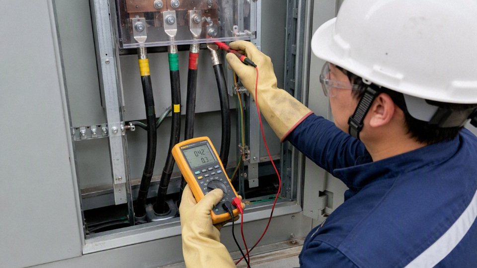
Routine testing methods used during maintenance
Routine testing is a mix of electrical measurement, thermal inspection, and plain physical inspection. The right package depends on the installation. A clean indoor MCC feeding fixed pumps does not need the same inspection frequency as a quarry trailing cable, a refrigerated washdown line, or a festoon system on a crane.
| Method | What it helps verify | Practical limitation |
|---|---|---|
| Insulation resistance testing | Leakage paths through insulation, moisture contamination, gross insulation breakdown | Results depend on temperature, humidity, cable length, connected equipment, and test voltage; old cables can be stressed by inappropriate testing |
| Continuity testing | Protective earth continuity, bonding links, conductor integrity | Low-resistance measurements need good lead compensation and clean contact points |
| Earth loop impedance testing | Whether a fault current path is low enough to operate protective devices within required time | Must be interpreted against the actual protective device and local code requirements |
| Residual current device testing | RCD/GFCI trip function and trip time at defined residual currents | Does not prove the whole installation is safe; it proves one protective device function under test conditions |
| Thermographic inspection | Loose joints, overloaded phases, high-resistance terminations, imbalance | Meaningful only under adequate load; a cold idle panel can hide a bad termination |
| Partial discharge monitoring | Insulation defects in medium-voltage and some high-voltage systems | Requires suitable sensors, trained interpretation, and trend data; not a casual handheld check |
| Sheath testing | Outer sheath damage, water ingress risk, faults to armor or earth in buried or armored cables | Test voltage and method must match cable construction and supplier guidance |
| Cable route inspection | Mechanical damage, poor support, chemical exposure, water pooling, unauthorized modifications | Depends on access; concealed routes may require covers, ducts, or trenches to be opened |
The mechanism is straightforward but often misunderstood. Insulation resistance testing applies a DC voltage and measures leakage current, so it tends to expose contamination, moisture, and insulation damage that create conductive paths. Earth loop impedance testing checks whether the return path for fault current is low enough to make the protective device operate quickly. Thermography sees heat produced by resistance at joints, but only when current is flowing; the same loose lug may look harmless on a Sunday shutdown and glow under Monday production load.
There is a trade-off. More frequent and more aggressive testing catches degradation earlier, but it costs downtime, labor, access equipment, and sometimes introduces risk if test leads are placed badly or old insulation is over-stressed. The preferred choice flips in harsh duty: on a clean, fixed, lightly loaded installation, inspection and trend-based testing may be enough; on wet, mobile, hot, chemically aggressive, high-vibration, or high-load circuits, short inspection intervals are cheap compared with nuisance trips, arc damage, or a shock incident.
A handheld voltage indication alone is enough to prove an industrial cable or enclosure is safe to touch.False
Voltage indicators are useful screening tools, but safety decisions also depend on verified isolation, meter category, protective earth continuity, insulation condition, fault-loop performance, and the test procedure required by the applicable electrical safety rules.
Warning signs that deserve investigation
Small symptoms often show up before a serious shock event. Maintenance teams should treat the following as electrical safety warnings, not just reliability complaints:
- Nuisance trips of breakers, RCDs, GFCIs, or insulation monitoring devices, especially after rain, washdown, startup, or high-load operation.
- Tingling sensations from machine frames, handrails, wet floors near equipment, portable tools, or cable glands. Stop and isolate the equipment; do not “try it again.”
- Damaged jackets, flattened cables, exposed braid, torn flexible conduit, crushed tray sections, or cable insulation polished shiny where it has been rubbing.
- Hot terminations found by thermography, smell, discoloration, brittle insulation, or melted labels.
- Moisture in glands, junction boxes, motor terminal boxes, pull pits, manholes, or bottom-mounted enclosures without working drains.
- Discoloration and cracked insulation, especially near heat sources, braking resistors, ovens, steam lines, roof penetrations, or outdoor black-sheathed cable in strong sun.
- Corrosion on earth bars, armor clamps, gland plates, door bonds, and enclosure seams.
- Unusual odor such as hot varnish, overheated PVC, phenolic smell from old panels, or ozone-like odor near switchgear.
- Noise from switchgear, including buzzing contactors, tracking sounds, crackling, or intermittent arcing.
- Unexplained voltage on enclosures, even if a non-contact tester gives inconsistent results.
That last point needs care. A high-impedance digital multimeter may show “ghost voltage” from capacitive coupling in a long parallel run, while a damaged cable may produce a dangerous touch voltage capable of delivering current. The way to separate those cases is not guesswork; qualified personnel use suitable meters, low-impedance measurement where appropriate, bonding checks, load checks, and isolation procedures.
Safe work practices during testing
Testing can expose workers to the same energy they are trying to control. Wrong meter category, damaged leads, poor probe contact, or a test performed on the wrong side of an isolator can turn a routine check into an arc-flash or shock event.
Minimum safe practice should include:
- De-energize whenever possible
- Plan shutdowns rather than making live testing the default.
- Use temporary bypasses or staged production stops only when approved by engineering and operations.
- Verify absence of voltage
- Use a meter rated for the installation category and voltage.
- Prove the tester on a known live source or proving unit before and after the test, as required by site procedure.
- Apply lockout and tagout
- Isolate all sources, including backfeeds, generators, UPS systems, VFD DC buses, control transformers, capacitors, and adjacent energized compartments.
- Do not rely on an HMI “off” command or a stopped motor as isolation.
- Discharge stored energy
- VFDs, capacitors, long cable runs, power-factor correction banks, and some test sets can retain charge.
- Follow the equipment manual for discharge time and verification method.
- Use rated PPE and insulated tools
- Select PPE from the site arc-flash and shock-risk assessment, not from habit.
- Keep gloves, face shields, mats, and tools inspected; damaged PPE gives false confidence.
- Control test leads
- Use fused leads where appropriate, shrouded probes, clips that cannot slip, and hands-free connections before energizing a test circuit.
- Keep one hand out of the panel where practical. Old advice, still useful.
Limits of handheld voltage testers and non-contact indicators
Non-contact voltage indicators are good for a quick warning, not for proving safety. They can fail to indicate on shielded cables, armored cables, metal conduit, wet surfaces, or conductors inside grounded enclosures because the electric field is contained. They can also indicate where no dangerous source is present because nearby energized conductors create capacitive coupling.
Handheld meters have their own traps:
- A high-impedance meter may display induced or ghost voltage that collapses under a small load.
- A low-impedance mode can help distinguish coupled voltage, but it must be used only where suitable and allowed by procedure.
- The wrong CAT rating can be fatal in distribution panels with high fault current.
- Leads with cracked insulation, exposed tips, missing finger guards, or cheap unfused construction are not minor defects.
- Measuring between the wrong reference points can miss a hazardous touch condition, especially on floating, impedance-earthed, or poorly bonded systems.
Testing should be performed by qualified personnel because the act of testing changes the risk: covers are open, barriers may be removed, probes are introduced, and the worker is close to live or potentially live parts. The correct method comes from the equipment manual, applicable standards such as IEC 60364, IEC 61140, IEC 60479, NFPA 70E, OSHA requirements, and local electrical rules, interpreted for the actual installation.
Maintenance intervals should be risk-based. Wet washdown equipment, outdoor junction boxes, mobile machines, cable reels, festoons, welding areas, chemical plants, high-temperature zones, high-vibration motors, and continuously high-load feeders deserve shorter intervals than clean, dry, fixed indoor circuits. No inspection schedule can guarantee that tomorrow’s forklift strike, loose gland, or roof leak will not create a new touch-voltage hazard; the schedule only works when operators are trained to report symptoms and maintenance has authority to isolate suspect equipment before production pressure normalizes the defect.
Standards and safety limits
Standards do not treat “voltage through skin” as one fixed number because shock injury depends on current, contact duration, path through the body, waveform, environment, and the protective system around the circuit. For industrial design, the safer approach is to use recognized shock-protection frameworks, then verify the actual installation against the local code and authority having jurisdiction.
IEC 60479 is usually the first technical reference I reach for when someone wants to understand why a harmless-looking voltage can become dangerous under the wrong contact condition. It deals with the effects of current on human beings and livestock, and its value is that it relates current magnitude and time rather than pretending that voltage alone defines the hazard. A brief tingle, a painful let-go problem, respiratory interference, and ventricular fibrillation risk sit in different parts of the current-duration picture.
That matters on the plant floor because protective devices operate in time, not just in theory. A breaker, fuse, residual current device, or insulation monitor has to limit how long a dangerous touch condition remains present. If a fault places a machine frame at a hazardous potential, the worker does not care whether the spreadsheet said the nominal system was “low voltage”; they care whether the protective earthing path is intact and whether the disconnection device clears fast enough.
There is one universal safe voltage that can pass through human skin.False
Recognized safety frameworks evaluate shock risk using current, duration, current path, AC versus DC waveform, skin condition, environment, and protective measures rather than a single skin-voltage number.
IEC 61140 and IEC 60364 put that physiology into protection principles for electrical installations and equipment. The language varies by edition and national adoption, so engineers should check the applicable documents rather than quote values from memory, but the design logic is familiar:
- Basic protection: prevents contact with live parts under normal operation, using insulation, barriers, enclosures, covers, or placement out of reach.
- Fault protection: reduces injury risk if basic insulation fails, typically by protective earthing, equipotential bonding, automatic disconnection of supply, or separation.
- Protective earthing and bonding: give fault current a low-impedance return path so metal enclosures do not remain energized. Loose lugs, painted bonding faces, corroded gland plates, and “temporary” green-yellow jumpers left in service are common weak links.
- Automatic disconnection: coordinates fault current, protective device type, circuit impedance, and trip time. The mechanism is simple: lower loop impedance generally produces higher fault current, which should make the protective device operate faster; poor connections or long undersized runs can stretch clearing time.
- Extra-low-voltage systems: reduce shock risk by limiting the voltage source and installation conditions, but they are not a permission slip to ignore wet locations, damaged insulation, stored energy, or special environments.
The trade-off is familiar to anyone who has priced a plant retrofit. Better shock protection may mean larger protective conductors, more residual current protection, better cable glands, double-insulated equipment, segregated circuits, or additional enclosures. That costs money and space, and nuisance tripping can become a production complaint if leakage currents, VFD filters, long cable runs, or washdown moisture are not considered. The preferred choice flips when uptime pressure tempts maintenance teams to bypass protection; at that point, the design has failed operationally even if it looked compliant on paper.
NFPA 70E approaches the issue from the workplace safety side. It is especially useful for maintenance managers, electrical supervisors, and procurement teams writing service contracts because it deals with shock risk assessment, approach boundaries, energized work justification, lockout/tagout planning, and PPE selection. A proper NFPA 70E-style review asks practical questions:
- Is the task justified energized, or can the circuit be placed in an electrically safe work condition?
- What nominal voltage and exposed conductor condition are present?
- Who is qualified for the work, and who is not allowed inside the shock boundary?
- What test instrument rating, PPE, insulated tools, and work controls are required?
- Has the worker verified absence of voltage using a proven live-dead-live method?
OSHA requirements, where applicable, sit in the enforcement and employer-duty layer. At a high level, they cover guarding of live parts, grounding and bonding practices, flexible cord use, temporary wiring, safe work practices, lockout/tagout expectations, and the distinction between qualified and unqualified personnel. In practice, OSHA problems often show up in unglamorous places: cracked extension cord jackets, open junction boxes above a packing line, missing strain reliefs, wet floors under portable equipment, or a panel door that no longer closes because someone added an oversized contactor.
Do not mix limits from different standards without checking the assumptions behind them. AC and DC do not produce identical physiological response. Dry indoor contact is not the same as wet skin inside a food plant wash bay. Normal operation is not the same as a single-fault condition. A touch lasting a fraction of a second is not the same as a worker frozen onto a conductor or trapped against an energized enclosure. Even frequency matters; most industrial shock discussions center on 50 Hz or 60 Hz AC, while variable-frequency drives, DC buses, welding systems, and capacitive circuits require more careful review.
Some sectors add another rulebook on top of the general electrical standards. Medical locations, mining, marine vessels, rail systems, explosive atmospheres, renewable energy plants, battery energy storage, and utility networks may impose different earthing methods, insulation monitoring, segregation, arc-flash controls, emergency shutdown, or environmental protection requirements. A cable that is perfectly reasonable for a dry factory submain may be unacceptable in a hazardous area, on a ship, or in a tunnel with smoke-toxicity restrictions.
Final design and acceptance belong to the applicable local code and the authority having jurisdiction, not to a generic voltage threshold copied from a chart. Manufacturers, consulting engineers, and qualified electrical contractors support that process by supplying correct cable ratings, insulation data, installation guidance, test documentation, certificates where applicable, and clear limits of use. The boundary of any standards-based conclusion is the actual installation: once moisture, damage, poor termination, incorrect protection settings, or unauthorized modification enters the picture, the paper limit has to be rechecked against the site condition.
Frequently asked questions
Can 12 volts pass through skin?
Yes, 12 V can drive current through skin, but dry, intact skin often limits that current to a level most people will not feel. The same 12 V across wet cuts, metal jewelry, sweaty hands, or a puncture probe can become noticeable and, in special cases such as medical electrodes or battery short circuits, hazardous.
In plant terms, 12 V control circuits are usually treated as low shock risk, not zero risk. The bigger day-to-day hazards are often short-circuit heating, arcing at battery terminals, and burns from rings or watch straps bridging a DC source.
Can 24 volts shock you?
24 V can shock you under wet, contaminated, or broken-skin conditions. I have seen technicians dismiss 24 VDC panels as “safe” and then work with sweaty forearms against grounded sheet metal; that is exactly the kind of contact condition that changes the calculation.
For dry hands, 24 V normally produces very low current. For wet skin below roughly 1,000 ohms, current can rise into the milliamp range, where tingling or involuntary reaction becomes plausible. That reaction can still cause secondary injury: jerking into a moving conveyor, dropping a tool into live terminals, or falling from a ladder.
Is 48 volts safe to touch?
48 V is commonly used because it is lower risk than mains voltage, but it is not automatically safe to touch. Many telecom, battery, solar, and control systems sit around this voltage class, and the safety result depends on skin condition, available fault current, grounding, connectors, and whether the circuit is isolated.
Any system below 50 volts is safe for bare-hand contact.False
Low voltage reduces shock probability, but wet skin, broken skin, conductive contamination, high available current, and unfavorable current paths can still create injury risk. Industrial decisions should follow the applicable standard and the actual installation conditions, not a single voltage number.
Why is 120 volts dangerous if skin resistance is high?
120 V is dangerous because skin resistance is not stable. A dry hand might measure tens of thousands of ohms one minute, then drop sharply with sweat, pressure, damaged skin, metal contact area, or a small puncture through the outer skin layer.
The mechanism is unforgiving: once current starts to flow, local heating and skin breakdown can reduce resistance further, which allows more current. At 50 Hz or 60 Hz, currents in the several mA to tens of mA range can cause painful shock, gripping, respiratory interference, or heart-risk conditions depending on path and duration. A 120 V circuit has enough voltage to push current into those ranges when the contact is poor from a safety standpoint.
Is 240 volts more dangerous than 120 volts?
With the same body resistance and contact path, 240 V can drive roughly twice the current of 120 V, so the shock severity can be worse. It also gives less margin when skin is damp or contact pressure is high.
That does not make 120 V “safe.” Many severe shocks happen at ordinary building voltages because the person is well grounded, the contact lasts long enough, or the current crosses the chest. Protection quality matters too: RCD/GFCI devices, grounding continuity, enclosure integrity, overcurrent coordination, and cable condition often decide whether a fault becomes a brief event or a serious injury.
Does AC pass through skin more easily than DC?
AC does not simply “pass through skin more easily” in every case, but 50 Hz and 60 Hz AC is generally more dangerous to the human body at lower currents than DC for many shock scenarios. Human tissue has resistive and capacitive behavior, and alternating current can interact strongly with nerves and muscles.
DC can still be dangerous, especially at higher voltages, with battery banks, rectifier systems, EV infrastructure, solar strings, and welding equipment. DC arcs can be harder to interrupt, and burns can be severe. The trade-off is practical: AC mains often presents greater fibrillation and muscular-control risk at common industrial voltages, while DC systems often bring high fault-current and arc-energy hazards that people underestimate.
Can wet skin make low voltage dangerous?
Yes. Wet skin can reduce impedance from more than 100,000 ohms in a dry, intact condition to below 1,000 ohms when wet, damaged, or punctured. Sweat, rainwater, washdown chemicals, metal dust, coolant, brine, and concrete slurry all make the contact more conductive.
The plant-floor version is simple: a voltage that feels harmless at a dry bench may be a different hazard in a wash bay, outdoor junction box, cooling tower platform, battery room, or food-processing area with caustic residue on gloves.
What voltage breaks down skin resistance?
There is no single voltage that “breaks down” skin resistance for every person or every contact. Breakdown depends on:
- Skin condition: dry, wet, abraded, cut, burned, or chemically irritated.
- Contact area: fingertip, palm, forearm, jewelry, probe tip, or tool edge.
- Contact pressure: light brush versus firm grip.
- Duration: momentary touch versus being unable to let go.
- Waveform: AC, DC, impulse, pulsed output, or high-frequency energy.
- Environment: humidity, conductive dust, salt water, coolant, or sweat.
- Source strength: available fault current and protective-device clearing time.
Once the outer skin layer is compromised, body impedance can fall quickly. That is why recognized frameworks such as IEC 60479 and NFPA 70E use conditions, current paths, and time-current effects rather than one universal “skin breakdown voltage.”
Can current pass through gloves or shoes?
Yes. Ordinary gloves and shoes are not reliable electrical insulation. Leather gloves, fabric gloves, nitrile shop gloves, oily cut-resistant gloves, and safety boots may reduce contact in some situations, but they can also become conductive when wet, dirty, torn, carbon-tracked, or contaminated with metal fines.
Use only properly rated insulating gloves and footwear where electrical isolation is part of the protection plan. Check:
- Voltage class and certification marking.
- Test date and inspection record.
- Pinholes, cuts, swelling, ozone cracking, and embedded wire strands.
- Cleanliness and dryness before use.
- Correct leather protectors over rubber insulating gloves where required.
- Whether the work procedure still requires lockout, test-before-touch, barriers, or arc-rated PPE.
Concrete floors are often damp enough to complete a path through footwear. Do not treat shoes as the only barrier between a worker and live voltage.
What should I do after an electric shock?
- Disconnect the power if it can be done safely; do not grab a person who may still be energized.
- Call emergency services for loss of consciousness, chest pain, breathing difficulty, confusion, burns, fall injury, shock through the chest, high-voltage exposure, or suspected heart rhythm symptoms.
- Get medical evaluation after any significant shock, especially if current may have passed hand-to-hand or hand-to-foot.
- Cool burns with clean running water if appropriate, but do not apply grease or break blisters.
- Report the incident and preserve the equipment condition for investigation.
- Do not re-energize the circuit until a qualified person has found and corrected the cause.
Even a “small” shock deserves respect if it happened in an industrial system. The fault that touched one person may still be waiting for the next technician.
How do cables prevent voltage from reaching people?
Cables prevent contact with live conductors through layers of engineering control, not just one piece of plastic. The insulation separates conductors electrically; the outer jacket protects against moisture, oil, abrasion, UV, and handling damage; shields, armor, grounding conductors, glands, and enclosures help control fault energy and touch voltage.
Good cable selection also considers:
- Rated voltage and insulation material.
- Temperature at the conductor and in the installation space.
- Oil, chemical, sunlight, flame, and moisture exposure.
- Flexing, torsion, drag-chain duty, or vibration.
- Crushing, impact, rodent damage, and sharp tray edges.
- Proper termination, strain relief, bend radius, and sealing.
- Compatibility with grounding and protective devices.
A cable that is electrically adequate on paper can still become unsafe if it is routed across a forklift path or terminated through a cheap gland that loosens every shutdown.
When should a damaged cable be replaced instead of repaired?
Replace the cable rather than repair it when the damage affects the conductor, insulation integrity, sealing, certification, or future reliability. A taped jacket scuff is one thing; a crushed, waterlogged, carbonized, or repeatedly flexed cable is another.
Replacement is usually the safer decision when you see:
- Exposed copper or broken conductor strands.
- Melted, brittle, cracked, swollen, or carbon-tracked insulation.
- Water ingress, oil saturation, or chemical attack under the jacket.
- Damage near a gland, plug, splice, or strain-relief point.
- Repeated faults after previous repair.
- Failed insulation-resistance, hipot, continuity, or grounding tests.
- Damage on fire-rated, safety-critical, elevator, crane, mining, marine, or hazardous-area circuits.
- Unknown repair history on a cable feeding high-value equipment.
Repairs need approved materials, qualified workmanship, and testing after completion. If the cable’s rating, environmental protection, or mechanical strength cannot be restored and verified, replacement is the cleaner engineering and procurement decision.
Verify your cable safety margin
No responsible electrical design should rely on human skin resistance as a protective layer. The safety margin has to come from the installation: correct cable insulation, earthing or bonding, protective-device coordination, mechanical protection, environmental suitability, and maintenance evidence that the system still performs as specified after months or years on the floor.
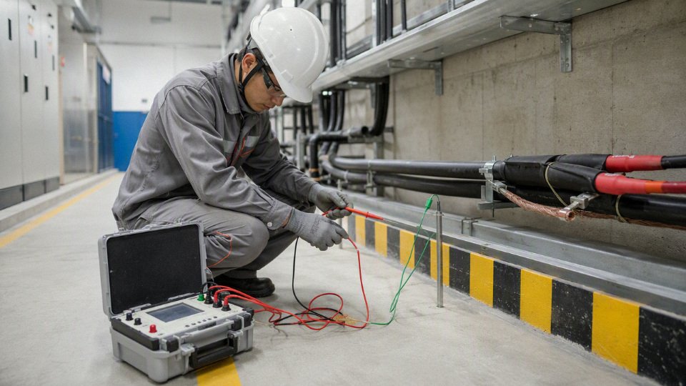
The practical mechanism is simple enough, but it is often missed during purchasing. Cable insulation prevents energized conductors from contacting accessible metalwork or wet surfaces; earthing gives fault current a low-impedance return path; fuses, breakers, RCDs, GFCIs, or protective relays disconnect the supply before a person becomes that return path. If one part is weak — a jacket cracked by oil, a gland with poor strain relief, a protective device oversized “to stop nuisance trips” — the whole safety margin shrinks.
Buyer verification checklist before issuing a purchase order
For procurement teams, the dangerous mistake is buying “same voltage, same conductor size” without checking the installation duty. A cable that is acceptable in a dry tray may be a poor choice on a washdown line, a festoon, a mining skid, or an outdoor export package sitting under UV for five years.
Ask for these details before locking the specification:
- System voltage
- Rated voltage phase-to-phase and phase-to-earth.
- Any transient, surge, inverter, or switching exposure.
- Whether the cable is for low-voltage power, control, instrumentation, or medium-voltage service.
- AC or DC service
- AC systems bring capacitance, frequency effects, and protective-device behavior into the review.
- DC systems need closer attention to arc interruption, polarity, insulation stress, and disconnect equipment.
- Available fault level
- Short-circuit withstand is not only a switchgear question. Cable conductor size, screen or armor design, and earthing conductor capacity must suit the fault current and clearing time.
- Installation environment
- Dry indoor tray.
- Wet processing area.
- Buried duct or direct burial.
- Outdoor exposure.
- Confined machinery space.
- Hazardous or classified area, where applicable.
- Wet or dry human exposure
- A cable near operators with wet gloves, metal platforms, washdown hoses, or conductive dust deserves a more conservative review than the same cable in a locked electrical room.
- Movement, flexing, crushing, and abrasion
- Fixed wiring, drag chain, reel, festoon, pendant control, and mobile equipment are not interchangeable duties.
- In practice, many early failures are mechanical first and electrical second: a jacket rubs through on a bracket, moisture enters, insulation resistance falls, then the breaker “mysteriously” starts tripping.
- Chemical, oil, temperature, and UV exposure
- Check compatibility with cutting fluids, solvents, fuel, wastewater chemicals, fertilizers, sunlight, and low-temperature handling.
- Seasonal cold matters; a cable that bends nicely in summer can split during winter maintenance.
- Fire performance
- Flame retardance, low-smoke performance, halogen content, circuit integrity, and local fire-code requirements must match the building, tunnel, shipboard, transit, or industrial risk.
- Earthing method and protective conductor arrangement
- Confirm whether the design depends on armor, copper tape, concentric conductor, separate PE core, conduit, or external bonding.
- Do not assume armor alone satisfies the project earthing requirement without calculation and documentation.
- Certification and applicable standards
- Define IEC, EN, BS, UL, CSA, NEC, local code, project specification, or customer standard requirements before quoting.
- Export projects need this early; changing certification after production is expensive and sometimes impossible.
- Factory test records and documentation
- Request routine test reports, construction data, datasheets, marking details, packing requirements, and compliance declarations required by the end user or authority.
The trade-off is usually cost, bend radius, weight, and lead time versus operating margin. Heavier armor, higher-grade sheathing, special fire performance, or screened construction may be justified where downtime or shock exposure is serious; it may be wasteful on a clean, fixed, indoor run with good containment and low mechanical risk. The preferred choice flips when the cable moves, gets wet, crosses operator access zones, or becomes part of a safety-critical machine.
Operator verification checklist after installation
Operators and maintenance teams should treat cable condition as a live safety control, not housekeeping. A plant can buy the right cable and still lose the margin through poor glands, dragged extension leads, missing bonding jumpers, or a well-meaning electrician upsizing a breaker to keep production running.
Use a routine check that includes:
- Inspect visible cable condition
- Cuts, swelling, hardening, flattening, exposed braid or armor, burn marks, cracked glands, loose cleats, and sharp contact points.
- Pay extra attention at cable entries, moving joints, tray exits, and places where operators step over cables.
- Confirm protective-device ratings
- Breaker, fuse, RCD, GFCI, overload, and relay settings should match the design.
- Any undocumented change after commissioning deserves investigation.
- Test earth continuity
- Verify bonding paths, protective conductors, armor terminations, and exposed conductive parts.
- A shiny new cable gland does not prove electrical continuity; paint, corrosion, loose locknuts, and wrong washers can defeat it.
- Measure insulation resistance
- Test using procedures, voltages, and acceptance values suitable for the equipment and cable type.
- Sensitive electronics, drives, and instrumentation may need isolation before testing, so follow the equipment manual and the site electrical safety procedure.
- Investigate tingling, shocks, nuisance trips, or odor
- A “small tingle” on a frame, hose reel, or wet control station is not a comfort issue. Treat it as an electrical fault report until proven otherwise.
- Remove damaged cables from service
- Tape is not a repair for damaged insulation in an industrial power circuit.
- Temporary measures should be controlled, documented, and replaced with a proper repair or cable changeout.
This operator checklist does not replace a qualified electrical assessment. Its boundary is reached when fault levels, protection coordination, medium-voltage testing, hazardous-area rules, or unexplained leakage currents are involved; those need a competent electrical engineer, the current equipment manuals, and the applicable code or standard.
When to involve a cable manufacturer or qualified electrical engineer
Bring in specialist support before purchase, not after the first failure, when the application has any of these features:
- Unusual heat, cold, oil, chemical, UV, immersion, or abrasion exposure.
- Export projects with mixed standards, documentation, and language requirements.
- Bulk procurement where a wrong construction becomes a container-load problem.
- Repeated cable failures, nuisance trips, insulation-test decline, or unexplained touch voltage.
- Medium-voltage systems, screened cables, armor earthing, or sheath bonding questions.
- Mobile equipment, drag chains, reels, cranes, mining machines, port equipment, or temporary power.
- Safety-critical installations where cable failure can expose workers, stop emergency systems, or shut down a major process line.
Jinda is set up for this type of technical supply discussion. Established in 1987, Shandong Jinda Special Cable Group Co., Ltd. operates five production bases, serves customers in more than 50 countries, and supports projects through an integrated system covering R&D, production, sales, technical support, and after-sales service. For international buyers, that matters because cable selection is not only conductor area and price per meter; it is construction suitability, repeatable manufacturing, documentation, packing, delivery planning, and long-term supply consistency.
Send Jinda’s technical team your operating voltage, AC or DC service, application, installation environment, movement or abrasion conditions, chemical or UV exposure, earthing method, required standards or certifications, fire-performance requirements, and procurement quantity. With those details, Jinda can recommend an appropriate cable construction and documentation package for your project.