A cheap roll of the wrong “underground wire” can turn into a wet splice fault, nuisance GFCI trips, a failed inspection, or a trench that has to be opened twice. That means lost labor, damaged landscaping, delayed equipment startup, and a small material saving that disappears fast. The right path is to select a cable assembly actually rated for direct burial, then size and protect it for the load, soil, and code jurisdiction.
You can run cable underground without conduit only if it is listed for direct burial, such as UF-B for many residential branch circuits or approved direct-burial feeder/service cable for larger loads. The exact choice still depends on voltage, ampacity, wet-location rating, soil exposure, burial depth, and local electrical approval.
The catch is that “outdoor,” “waterproof,” and “underground” are not interchangeable labels. Some conductors are wet-location rated but still need raceway, some cables can be buried directly but need protection where they emerge, and burial depth can shift from roughly 6 to 24 inches depending on the wiring method and protection scheme.
Acceptable direct burial cables
Acceptable direct-burial cable is not defined by appearance, jacket thickness, or a salesman saying “outdoor rated.” It must be marked, listed, and installed for direct burial and wet locations, with conductor size, insulation, jacket, ampacity, mechanical protection, and local code approval matching the job. If the cable legend or data sheet does not explicitly support direct burial, do not bury it bare.
UF-B cable for residential branch circuits
UF-B is the common cable homeowners and small contractors run into yards for branch circuits: detached garages, post lights, sheds, small pumps, gate operators, and similar loads. It is built with solid or stranded copper conductors embedded in a moisture-resistant nonmetallic jacket, usually with the equipment grounding conductor included. Unlike NM-B, the individual conductors are not just wrapped in a dry indoor sheath; the assembly is intended for damp and wet underground exposure when installed within its listing and code limits.
The practical limitations matter. UF-B is usually used at 600 V class for smaller branch circuits, and ampacity is governed by conductor size, insulation temperature limits, termination ratings, bundling, ambient conditions, and the applicable electrical code. It is stiff, especially in cold weather. Pulling UF-B through a long sleeve or a tight riser can become a knuckle-busting job, and I have seen jackets shaved by a rough PVC male adapter because someone treated it like THHN in conduit.
UF-B is not interchangeable with indoor NM-B. NM-B may look similar to a non-electrician, but it is not built or marked for direct burial or wet underground locations. A cable that survives one season in the soil is not the same thing as a legal, inspectable, long-life installation.
USE-2 and service-entrance conductors
USE-2 conductors are widely used for underground service laterals and similar outdoor service-entrance work. They are made for wet locations and direct burial when properly marked, and many versions also carry sunlight-resistant markings for exposed risers or outdoor equipment zones. In practice, utilities, electrical contractors, and site crews like them because they are available in larger sizes and in aluminum or copper, with insulation systems suited to underground exposure.
The catch is the transition into the building. Some USE conductors are not permitted for general interior building wiring beyond the allowed service point or transition location. That limitation gets missed during value engineering: the estimator prices USE because it is cheaper or familiar, then the field crew tries to continue it into a panel room where the wiring method is no longer allowed. The fix is not a creative interpretation; it is selecting a conductor with the right additional ratings or transitioning to an approved wiring method at the proper location.
Typical USE-2 applications include:
- Underground utility service laterals from transformer or pedestal to service equipment
- Direct-buried feeders where allowed by code and approved by the authority having jurisdiction
- Outdoor risers when sunlight resistance and mechanical protection requirements are satisfied
- Large residential, farm, and light commercial services where aluminum conductors make economic sense
Dual-rated conductors such as USE-2/RHH/RHW-2
Dual-rated conductors solve a common boundary problem: the same conductor may need to live underground, pass through a conduit riser, enter service equipment, and sometimes continue into a building wiring zone. A conductor marked USE-2 only may be suitable for the buried portion but restricted once it enters the structure. A conductor marked USE-2/RHH/RHW-2 gives the designer and installer more room, provided every marking is valid for the actual installation.
The markings are not decoration. RHH and RHW-2 ratings relate to rubber or cross-linked insulation types and wet-location or high-temperature use, depending on the specific construction and standard. USE-2 handles the underground service-entrance side. When a feeder leaves a pad-mounted transformer, runs underground, rises in conduit, and terminates in switchgear, the dual or multiple ratings can keep the installation from needing awkward splice boxes simply to change conductor type.
The trade-off is cost and procurement discipline. Multi-rated conductors may cost more than the lowest-priced single-use product, and substitutions can quietly remove the rating that made the design legal. On larger projects, the purchase order should call out the complete marking string, conductor material, size, stranding, insulation type, voltage class, color requirements, reel lengths, and required certifications.
Direct-burial feeder cables for site power and distributed equipment
Larger feeders are common in commercial sites, farms, water systems, solar arrays, outdoor lighting, marinas, fuel facilities, and industrial yards. These may be single-conductor assemblies, multi-conductor feeder cables, or purpose-built power cables with an overall jacket. The deciding issue is not whether the cable is “heavy duty”; the jacket and listing must explicitly allow direct burial.
These feeders must be selected around several variables:
- Load current and allowable ampacity under the installed conditions
- Voltage drop, often designed around roughly 3 percent for branch circuits and 5 percent combined feeder plus branch circuit unless the project specification is stricter
- Soil thermal conditions, grouping, raceway sleeves, and backfill
- Equipment grounding or concentric neutral requirements
- Jacket resistance to moisture, abrasion, sunlight, oil, chemicals, and rodents
- Termination space inside panels, disconnects, combiner boxes, and motor controls
The mechanism behind voltage drop is simple but expensive when ignored: conductor resistance turns part of the delivered power into heat along the run, so the load sees lower voltage. A 60 A pump feeder that looks acceptable on ampacity may still have nuisance trips or hard starts if the run is long and the motor sees sag at startup. Upsizing the conductor improves voltage performance and reduces losses, but it increases material cost, lug size, bending radius, and sometimes trench handling labor.
Type TC-ER or tray cable marked for direct burial
Type TC-ER tray cable can be a good fit in industrial plants, renewable-energy sites, skids, conveyors, and distributed equipment where multi-conductor power and control circuits need a rugged jacketed cable. Some tray cables are marked for direct burial; some are not. The installation rules for tray cable, exposed runs, transitions, supports, mechanical protection, and terminations are installation-specific, so the cable marking alone does not approve the whole job.
Where TC-ER works well, it reduces wiring complexity. A packaged pump station, for example, may need power conductors, control conductors, and shielded signal pairs routed from a control panel to field equipment. A properly selected tray cable can be cleaner than a bundle of individual conductors, especially where the cable exits tray and drops to equipment under an allowed exposed-run provision. But if the same cable is dragged across crushed rock, left unsupported at a riser, or terminated through the wrong gland, the weak point becomes installation quality rather than cable design.
Armored direct-burial cable
Armored direct-burial cable is selected when the site will punish a plain jacket. Metallic armor, interlocked armor, corrugated armor, metal-clad constructions, and hazardous-location cable designs may be used where permitted for impact exposure, rodents, rocky backfill, industrial vehicle traffic, utility corridors, mining areas, petrochemical sites, or locations where excavation damage risk is higher.
Armor does not make the cable indestructible. It improves mechanical resistance, but it adds cost, weight, bending stiffness, termination complexity, and corrosion questions. In wet or chemically active soil, armor material, jacket over armor, bonding method, and grounding continuity need engineering review. For hazardous locations, the cable type, glands, sealing requirements, grounding path, and area classification have to be checked against current code and project documents, not guessed from a catalog photo.
Medium-voltage direct-burial cable
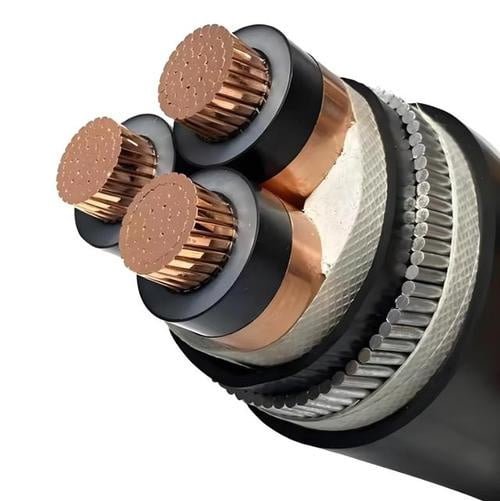
Medium-voltage direct-burial cable is a different class of product from residential UF-B or low-voltage feeders. It is used in industrial plants, substations, mines, ports, campuses, wind and solar projects, and utility distribution. These cables typically include a conductor shield, insulation such as XLPE, tree-retardant XLPE, or EPR, an insulation shield, metallic shield or concentric neutral, and an outer jacket selected for the environment.
The shield system controls electric stress around the conductor and insulation. Without proper shielding and stress control, medium-voltage terminations become failure points; the electric field concentrates at cutback edges, moisture migrates, partial discharge can develop, and the cable may fail long before its expected service life. That is why medium-voltage direct burial is not just a cable purchase. It requires engineered terminations, splice kits, trained installers, testing procedures, grounding design, pulling tension checks, and bend-radius control.
Jacket choices are project-specific. Polyethylene may provide strong moisture and abrasion resistance, PVC may offer different flame and handling characteristics, and low-smoke or halogen-free options may be specified where fire behavior in certain routed sections matters. The best choice flips when the installation changes from open earth to tunnel, tray, duct bank, or occupied-building interface.
Submersible pump and well cable
Submersible pump cable and well cable are designed around wet service, pump leads, and continuous or intermittent submersion conditions that ordinary direct-burial power cable may not tolerate. A cable can be suitable for burial yet not suitable for immersion in a well casing. The reverse can also be true depending on listing, jacket, and installation method.
Check these markings and details before buying:
- Wet-location and submersible service rating
- Pump manufacturer requirements
- Conductor count, grounding conductor, and motor lead configuration
- Jacket material compatibility with water, minerals, oil traces, or treatment chemicals
- Splice kit suitability for submerged service
- Temperature and voltage rating
- Strain relief at the pump and at the wellhead
A failed splice 180 feet down a well is not a cheap electrical repair. It becomes a pump-pulling job, and the cable savings disappear fast.
Low-voltage, communication, and control cable
Landscape lighting cable, Ethernet, coaxial, instrumentation, security, gate-control, irrigation-control, and process-control cables each need their own outdoor, wet-location, sunlight-resistant, and direct-burial ratings. Power-cable logic cannot be transferred to signal cable. A tough-looking black jacket does not mean the insulation system, shielding, water blocking, or electrical performance will survive underground.
For data and instrumentation, moisture can change impedance, increase leakage, corrode shields, and create intermittent faults that are miserable to troubleshoot. Direct-burial Ethernet, for example, may use gel filling, water-blocking tape, polyethylene jackets, or shielded constructions depending on exposure and noise environment. Control cable near variable-frequency drives, large motors, or solar inverters may need shielding and grounding details reviewed as part of the whole system, not just the trench route.
Copper versus aluminum conductors
Copper carries more current than aluminum at the same size and is usually easier to terminate in tight equipment. It is also heavier and normally more expensive. Aluminum is widely used for larger underground service and feeder conductors because it cuts material cost and weight, but it needs larger conductor sizes for equivalent ampacity and voltage drop.
The selection is rarely ideological; it is a termination and economics problem. Aluminum requires lugs rated for aluminum or dual-rated copper/aluminum use, proper oxide inhibitor where required by the connector manufacturer, correct stripping practice, and torque applied with a calibrated tool. Retorquing habits vary by plant, but random “one more pull” with a long Allen wrench can damage lugs just as surely as undertorque can create heat. Some codes or equipment listings also impose minimum size limits or restrict aluminum on small branch circuits, so verify the current rules and device markings.
Indoor NM-B cable may be directly buried if it is placed deep enough.False
Burial depth does not change the cable listing. NM-B is for dry interior locations and is not a substitute for cable marked for direct burial and wet underground use.
Insulation and jacket materials
Material selection controls how the cable behaves during installation and aging.
| Material | Practical strengths | Watch points |
|---|---|---|
| PVC | Common, economical, decent general-purpose jacket, familiar to installers | Can stiffen in cold weather; chemical, sunlight, and flame performance depend on formulation and marking |
| XLPE | Good thermal and electrical performance; common in power and medium-voltage cables | Less flexible than some rubber-like systems; termination practices must match the cable design |
| EPR | Flexible, strong electrical performance, often used in demanding power and medium-voltage service | Usually higher cost; jacket and shield system still determine burial suitability |
| Polyethylene | Strong moisture resistance and abrasion performance in many buried applications | Flame performance may be unsuitable for some exposed or indoor routed sections unless specifically rated |
| Halogen-free or low-smoke compounds | Useful where smoke and corrosive gas behavior is specified | Not automatically better underground; mechanical, wet-location, and sunlight ratings still need proof |
Soil chemistry, seasonal water table, freeze-thaw movement, insects, rodents, and backfill quality all influence service life. Sand bedding and warning tape are not glamorous line items, but they prevent a lot of failures caused by sharp stone pressure and future digging.
The marking rule
Before releasing a direct-burial cable order, verify the evidence chain, not just the catalog description. At minimum, check:
- Printed cable legend for direct-burial, wet-location, voltage, temperature, sunlight, and conductor markings.
- Reel tag against the purchase order and approved submittal.
- Manufacturer data sheet for permitted installation methods.
- Certification or listing documents required by the project and local authority.
- Conductor material and stranding against termination lugs.
- Jacket material against soil, sunlight, oil, chemical, rodent, or abrasion exposure.
- Burial depth and mechanical protection against the current electrical code, utility rules, and local amendments.
- Transition points into risers, buildings, handholes, panels, and equipment.
In procurement, I prefer the purchase description to include the exact marking requirement rather than a loose phrase such as “underground cable.” That one line prevents substitutions that look harmless in the warehouse but become inspection delays after the trench is open.
Cables needing conduit
A cable needs conduit when its listing depends on a raceway for moisture protection, mechanical protection, or installation method, even if the insulation itself is marked for wet locations. The common mistake is treating “wet-rated” as the same thing as “direct burial”; those are not interchangeable approvals. Inspectors reject a lot of underground work for that reason, especially where a familiar indoor or service cable was substituted for a true direct-burial product.
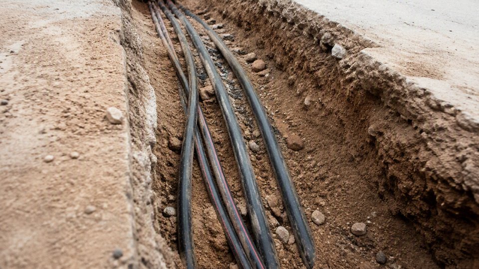
Common problem categories include:
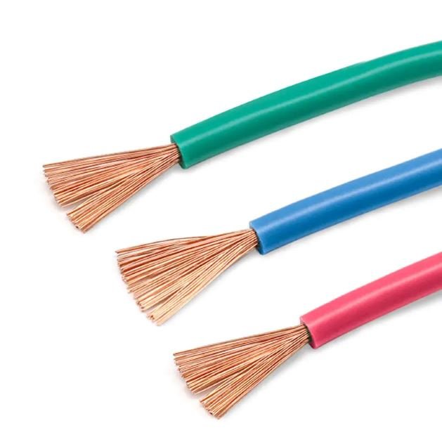
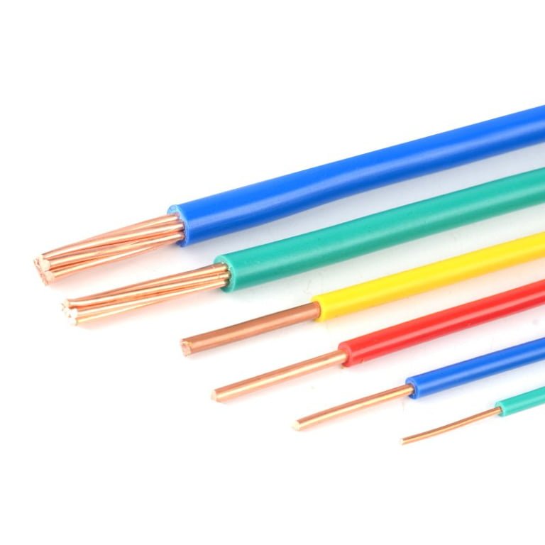
- THHN and THWN-2 individual conductors
THWN-2 is rated for wet locations, and many modern building wires are dual-marked THHN/THWN-2. That does not mean you can lay individual conductors directly in soil. These are normally pulled inside an approved raceway such as PVC conduit, rigid metal conduit, intermediate metal conduit, or another wiring method accepted by the authority having jurisdiction.
The reason is partly mechanical and partly listing-based. Individual conductors do not have the same outer jacket system as a direct-burial cable assembly, so soil movement, stones, backfill compaction, insects, and abrasion can damage insulation over time. In practice, if a contractor tosses loose THWN-2 into a trench and backfills it, the installation may energize fine on day one and still be wrong. - NM-B indoor building cable
NM-B, often called indoor Romex-type cable, is not designed for wet underground service. It should not be used as underground cable, and it is usually not acceptable even when pulled through underground conduit, because underground raceways are considered wet locations under typical code treatment.
This surprises people because the conduit “feels” like protection. Anyone who has opened a buried PVC junction or LB after a winter thaw knows better: condensation, groundwater seepage, and temperature cycling put water inside underground raceways. NM-B has construction features such as fillers and jacket materials intended for dry building interiors, not long-term wet conduit. SER, SEU, and other service-entrance cables used by assumption
Service-entrance cable is not automatically underground cable. SER and SEU markings, conductor insulation types, jacket construction, and permitted uses must be checked against the current code, manufacturer literature, and local inspection practice before anyone assumes underground suitability.
This is a procurement trap: the words “service entrance” sound heavy-duty, so buyers may approve it for a lateral, yard run, detached garage feed, or pedestal-to-building route. The right underground service cable may carry different markings, such as USE-type designations or other wet-location/direct-burial approvals depending on the system. The label on the reel matters more than the sales description on the invoice.Ordinary extension cords and flexible cords
Flexible cords are not permanent underground wiring methods. They should not be buried to feed pumps, pond equipment, temporary workshops, holiday lighting, sheds, gate motors, livestock water heaters, or jobsite tools.
The failure mode is predictable: the cord jacket hardens or cracks, the plug end gets improvised into a box, or a mower, shovel, dog, or frost movement damages the cable. Even if a GFCI trips before someone is hurt, you still have a noncompliant installation that is hard to locate and tempting for the next person to “repair” with tape.Non-direct-burial landscape, control, alarm, speaker, or data cable
Low voltage does not remove the underground requirements. Moisture migration, jacket degradation, rodent damage, UV exposure at risers, crush damage, and corrosion at terminations still apply.
Some low-voltage cable is made for direct burial, gel-filled communication use, irrigation control, tracer service, or outdoor-rated landscape circuits; some is not. The distinction is in the cable marking and datasheet, not in the fact that the circuit is 12 V, 24 V, or signal-level. A nuisance failure on a speaker line is one thing; a corroded control cable that drops out a pump, gate, or safety interlock at the wrong time is a different maintenance problem.Bare or inadequately insulated conductors
Bare copper or bare aluminum has legitimate underground uses in grounding electrodes, grounding electrode conductors, and bonding arrangements where permitted. That does not make bare wire acceptable as a current-carrying underground circuit conductor.
Feeders, branch circuits, pump circuits, lighting circuits, and control circuits need conductors with insulation systems and installation methods suitable for the environment and voltage involved. Soil is not an insulating system. It changes moisture content, chemistry, temperature, and contact pressure all year.
There is also a counter-intuitive case: a cable may be direct-burial rated and still need conduit in part of the run. Typical examples include:
- exposed risers up poles, walls, or posts;
- entrances into buildings, panels, disconnects, and meter areas;
- passes through foundations or sleeves where edges can abrade the jacket;
- areas under driveways, equipment yards, farm lanes, or paved crossings;
- transitions near HVAC pads, pump bases, bollards, and landscape edging;
- any place the cable is subject to physical damage from traffic, tools, settlement, or maintenance work.
That conduit is not always the primary wet-location wiring method; sometimes it is simply a protective sleeve. The design trade-off is straightforward: direct burial can reduce material and labor cost over a long open trench, but conduit provides better replaceability and protection at vulnerable points. The preferred choice flips when the route is likely to be disturbed, extended, repulled, or inspected in a jurisdiction that takes a stricter view of physical damage.
Many failed installations are not caused by choosing a completely absurd product. They are caused by using a legitimate wet-rated conductor, service cable, or low-voltage cable outside the wiring method it was listed for. Before buying a pallet of cable for an underground job, verify the exact print legend on the jacket, the intended wiring method, required burial cover, wet-location suitability, ampacity, and any local amendments with the project drawings and the authority having jurisdiction.
Burial depth and routing
Burial depth is not just “how deep the trench was on the day the crew dug it.” For code and inspection purposes, underground cover is normally measured from finished grade to the top of the cable, raceway, or protective layer, so bedding thickness, cable diameter, backfill settlement, future grading, and surface finish all matter. A direct-burial job can fail inspection even when the trench looked deep enough before the cable went in.
Underground burial requirements are normally based on minimum cover from finished grade to the top of the cable or raceway, not simply the excavated trench depth.True
This is the practical inspection logic used with NEC Table 300.5 and similar local rules; the exact required cover depends on wiring method, location, circuit conditions, and authority having jurisdiction.
NEC Table 300.5 is often where the conversation starts in U.S. projects, but it is not a single universal depth. Typical underground cover requirements can fall roughly from 6 to 24 inches depending on the wiring method, circuit rating, voltage, GFCI protection, location, traffic exposure, and local amendments. A residential garden circuit is not treated the same as a commercial parking lot feeder, and a cable directly in earth is not treated the same as wiring pulled through rigid metal conduit.
Cover depth depends on the wiring method and exposure
The common mistake is assuming “no conduit” means less work. Sometimes it does. In many cases, direct-burial cable requires more cover than rigid metal conduit or certain protected raceway methods, so the savings in conduit, fittings, pulling labor, and corrosion management may be partly offset by deeper excavation and more careful backfill.
In practice, the required depth is driven by several checks:
- Wiring method: Direct-burial cable, PVC raceway, rigid metal conduit, intermediate metal conduit, and other approved methods can have different cover requirements.
- Circuit type and rating: Branch circuits, feeders, low-voltage controls, service conductors, and higher-energy circuits are not interchangeable from a burial-risk standpoint.
- Voltage and GFCI protection: Some 120 V or lower residential branch circuits with GFCI protection and limited current may qualify for reduced cover, but only when every condition in the rule is met.
- Location: Residential yards, commercial landscaped areas, driveways, parking lots, agricultural ground, and industrial yards carry different damage risks.
- Surface loading: A cable under grass sees shovels and sprinkler repairs; a cable under a loading apron sees wheel loads, rutting, future saw-cutting, and maintenance excavation.
- Local rules: The authority having jurisdiction, utility owner, campus standard, or project specification can be stricter than the base code.
That last point causes arguments during procurement. A buyer may select a cable correctly marked for direct burial, but the installer still has to meet the routing and cover requirements for that jobsite. Cable approval does not erase trenching requirements.
Reduced cover cases need all conditions satisfied
Reduced cover allowances are useful, but they are narrow. A typical example is a residential branch circuit rated 120 V or less, GFCI protected, and limited in current, installed in a qualifying location. If one condition drops out, the reduced cover assumption may drop out with it.
The usual verification sequence is:
- Confirm the circuit voltage and overcurrent protection.
- Confirm the GFCI protection type and where it is installed.
- Confirm the installation is within the location covered by the reduced-depth rule.
- Confirm the wiring method is explicitly permitted for that cover.
- Confirm the finished surface will not later become a driveway, patio base, equipment pad, or hardscape.
- Get the AHJ or project inspector aligned before the trench is closed.
I have seen this go wrong on small outbuildings and gate circuits: the electrical work is designed as a simple residential branch circuit, then the owner later adds gravel access for a trailer or compact tractor. The original route may no longer match the exposure that justified the shallow cover.
Route selection matters as much as cable selection
Higher-risk routing zones deserve a more conservative design. Driveways, road crossings, parking areas, farm lanes, and industrial yards are where direct-burial cable is most likely to be crushed, cut, exposed, or forgotten during future work. In these areas, deeper cover, sleeves, concrete encasement, warning slabs, or a change to raceway may be necessary even if the cable itself is rated for burial.
Common routing risks include:
- Driveways and parking areas: Vehicle loading, resurfacing, bollard installation, fence posts, drainage cuts, and future trenching.
- Road crossings: Settlement, road authority requirements, boring damage, and compaction standards.
- Agricultural fields: Deep tillage, drainage tile repair, subsoiling, livestock water-line work, and seasonal soil movement.
- Industrial yards: Forklift traffic, scrap handling, crane mats, temporary foundations, grounding grids, and undocumented utilities.
- Landscaped areas: Root growth, irrigation repairs, edging tools, lighting upgrades, and grade changes from mulch or soil removal.
The trade-off is straightforward: the shortest route is rarely the most maintainable route. A straight diagonal across a yard may use less cable today, but a route along a fence line, building edge, or documented utility corridor is easier to locate, mark, protect, and avoid later. The preferred choice flips when voltage drop, cable cost, or easement restrictions make the longer route impractical; then mechanical protection and documentation become more important.
Separation from other utilities
Underground electrical routes should not be treated as empty real estate between buildings. Maintain required separation from gas, water, sewer, steam, fuel lines, communications, cathodic protection conductors, grounding electrodes, and other electrical circuits according to utility rules, project standards, and local code. The exact spacing is not something to guess from a generic chart because utility owners often have their own requirements.
Pay attention to crossings as well as parallel runs. A crossing may need vertical separation, a sleeve, a warning marker, or a specific angle so future crews can identify it. Steam lines and fuel systems need special caution because heat, chemical exposure, and maintenance access can shorten cable life or create safety conflicts. Communication cables also need coordination; the issue is not only electrical interference, but accidental damage during repair work when one utility crew exposes another system.
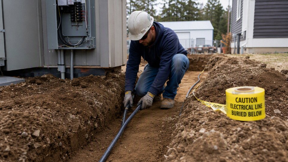
Bedding, backfill, and marking are part of the installation
Direct-burial cable is designed for soil contact, not for being crushed into broken concrete, slag, sharp limestone, scrap metal, welding rod stubs, or chemical-contaminated fill. The mechanism is simple: point loading damages the jacket, small jacket cuts admit moisture, and repeated wet-dry or freeze-thaw cycling turns a minor scrape into an insulation problem over time.
A durable trench detail normally addresses:
- Bedding: Use sand, screened soil, or other approved bedding where native soil contains sharp rock or debris.
- Initial cover: Place clean material around and above the cable before machine backfilling.
- Mechanical protection: Use protective slabs, boards, sleeves, or raceway where required by the design or inspector.
- Warning tape: Install at the specified height above the cable so it is found before a shovel or trencher reaches the conductor.
- Detectable marking: Use detectable tape, marker balls, tracer wire for nonmetallic systems where required, or other locating provisions.
- Route records: Keep as-built route maps with dimensions from durable references, not just “runs to shed.”
- Above-grade identification: Label risers, junction points, pull boxes, and transition locations so maintenance staff know what is underground.
Warning tape is cheap; undocumented excavation is not. On plant sites, I prefer a route record tied to building corners, column lines, or fixed equipment foundations rather than landscaping features. Shrubs move. Maintenance shops remember old routes badly.
Frost, erosion, grading, and transitions
The installed cover depth can change after energization. Frost heave, erosion, drainage work, landscaping, trench settlement, resurfacing, and root growth can all alter the distance between finished grade and the cable. A compliant installation at turnover may become marginal if a swale washes out or a contractor later cuts grade for paving.
Transitions are another weak point. Direct-burial cable may be allowed underground without continuous conduit, but vertical rises out of the ground commonly need conduit, guards, or other physical protection. That includes risers at buildings, poles, pedestals, equipment pads, junction boxes, and exterior disconnects. UV exposure, weed trimmers, snow shovels, forklifts, and casual foot traffic all attack the same vulnerable zone where the cable leaves the soil.
The safe design boundary is this: direct burial makes sense where soil conditions, cover depth, route control, and future excavation risk are predictable. Where the route crosses traffic, utilities, chemical exposure, unstable grade, or heavy maintenance activity, the installation may still use direct-burial cable in parts, but the routing plan should include sleeves, raceway, encasement, or rerouting before the trench is priced.
Soil and water risks
Underground cable should be selected for the soil it will live in, not just for the minimum burial rule on a code table. A cable that is legal on paper can still age badly if it sits in wet clay, fertilizer runoff, contaminated fill, hot backfill, or a trench full of sharp rock. The durable installation is usually the matched system: insulation, jacket, bedding, drainage, thermal allowance, accessories, and workmanship.
Underground conduit should be treated as a dry location if the pipe is glued and buried correctly.False
Underground raceways commonly collect water through condensation, groundwater movement, imperfect seals, and temperature cycling. Conductors and cables used in underground raceways must be suitable for wet locations where required by the applicable code and authority having jurisdiction.
Moisture is the normal condition underground
Treat every underground trench and raceway as wet service unless a qualified project specification proves otherwise. Water reaches cable through several paths:
- Groundwater rise after rain or snowmelt, especially in low spots, swales, and poorly drained sites.
- Condensation inside conduit, caused by temperature swings between buried pipe and above-grade risers.
- Capillary movement through soil, where fine soil pulls moisture toward the cable even without standing water.
- Seasonal flooding, common around farms, parking lots, irrigation zones, and coastal or riverside sites.
- Water tracking along cable ends or accessories, if terminations, splices, or sealing fittings are not chosen and installed correctly.
This is why wet-location marking is not a paperwork detail. It is part of the cable’s survival plan. Direct-burial cable may be designed to tolerate soil contact, but that does not make every termination, splice kit, connector, or transition fitting equally suitable. I have seen good cable installations fail at a buried splice because the kit was treated like a dry junction box component.
Water trees and insulation aging
In polymeric insulation, long-term moisture and electrical stress can create microscopic degradation paths often called water trees. They are not roots you can see with the naked eye; they are tiny, branched regions in the insulation where moisture, impurities, voltage stress, and defects gradually reduce dielectric strength.
The risk increases when several conditions line up:
- Continuous moisture exposure around the cable.
- Voltage stress, especially on medium-voltage cable or lightly overbuilt insulation systems.
- Poor jacket integrity, including cuts, pinholes, scrape damage, or rodent damage.
- Manufacturing voids or contamination, which reputable cable manufacturers work hard to control through material handling and extrusion quality.
- Improper accessories, where the insulation screen, shield, or stress control system is not restored correctly.
The trade-off is cost and handling. A more robust jacket, water-blocking construction, or higher-grade insulation system may cost more and have a larger bend radius, but it can prevent failures that only appear after years in service. For temporary low-voltage landscape work, that extra construction may not pay back. For a feeder to a pump station, solar field, or remote building where excavation is expensive, it often does.
Soil chemistry attacks more than the jacket
Soil is not chemically neutral just because it looks clean. Before buying cable in bulk for a site, look for conditions that can attack jackets, armor, shields, neutrals, connectors, and grounding components:
- Acidic soil, often found in peat, mine areas, some wooded sites, and industrial land.
- Alkaline soil, including lime-stabilized fill and some arid-region soils.
- Sulfates and chlorides, which can accelerate corrosion of metallic components.
- Hydrocarbons, including fuel, oil, solvents, and contaminated industrial fill.
- Fertilizers and manure runoff, common around farms, greenhouses, and landscaped commercial sites.
- Deicing salts, especially near roads, loading docks, sidewalks, and parking lots.
- Industrial wastewater or process leakage, where ordinary jacket assumptions may not hold.
PVC, polyethylene, cross-linked polyethylene, rubber compounds, metallic armor, lead sheaths, copper neutrals, aluminum armor, and galvanized components do not respond the same way to these exposures. The project should verify chemical resistance against supplier documentation when soil contamination is known or suspected. A cheap soil sample is often easier to justify than digging up a failed feeder under a finished yard.
Heat can be trapped underground
Ampacity is not only about conductor size. Underground cable must shed heat through insulation, jacket, bedding, and soil. If the surrounding material holds heat, conductor temperature rises and the allowable current may need derating.
Common heat problems include:
- Dry sand, which can have poor thermal contact and higher thermal resistivity than expected.
- Compacted clay, which may shed heat differently depending on moisture content.
- Concrete encasement, useful for protection but not automatically favorable for heat dissipation.
- Clustered circuits, where one cable heats the next.
- Poorly drained or backfilled trenches, where voids, rubble, or inconsistent bedding create hot spots.
The mechanism is simple: higher soil thermal resistivity slows heat flow away from the conductor, the conductor runs hotter, insulation ages faster, and voltage drop may worsen under load. The preferred choice flips depending on the site. Sand bedding may protect the jacket from rocks, but if it dries out and has poor thermal performance, it can reduce ampacity unless the design accounts for it.
Mechanical and biological damage
A cable buried without conduit relies heavily on the trench environment and jacket toughness. The common mechanical threats are not exotic:
- Sharp rocks and construction debris pressing into the jacket.
- Settlement, especially where trenches cross disturbed fill.
- Trench wall collapse during installation, which can kink or scrape cable.
- Vehicle loading, including forklifts, farm equipment, trucks, and compactors.
- Future excavation strikes, often from irrigation repair, fence posts, grading, or utility work.
- Frost heave, which can move cable, risers, and shallow transitions.
- Abrasion during laying or pulling, particularly when installers drag cable across gravel or over the lip of a trench.
Rodents, insects, and wildlife deserve attention in farms, solar fields, remote pump sites, rail corridors, and landscaped areas. Gophers, rats, squirrels, ants, termites, and burrowing animals do not read cable markings. In those locations, tougher jackets, metallic armor, ducts, warning tape, protective boards, or a deliberate conduit section may be justified even if a direct-burial cable is otherwise permitted.
Corrosion, galvanic effects, and sunlight exposure
Aggressive soil can corrode metallic armor, concentric neutrals, shields, grounding conductors, clamps, and connectors. Mixed-metal systems add another problem: galvanic interaction. Copper, aluminum, galvanized steel, stainless hardware, and ground rods can create corrosion cells when moisture and conductive soil complete the circuit. The fix is not guessing; it is matching compatible metals, using listed connectors, applying proper corrosion protection, and checking project grounding requirements.
Sunlight is easy to overlook before burial. Cable staged outdoors for weeks, or exposed at risers above grade, may need sunlight-resistant marking or mechanical protection where required. Black jacket does not automatically mean UV-rated, and a riser on the south side of a building can age faster than the buried length ever will.
The boundary on all of this is the actual installation environment. In clean, well-drained soil with modest loads and careful bedding, a standard listed direct-burial product may be entirely appropriate. In contaminated, hot, rocky, wet, or animal-active ground, the safest procurement question is not “What is the thickest cable?” but “Which complete underground system is qualified for this site and still installable by the crew we have?”
Sizing and voltage drop
A direct-burial cable is not “sized” just by matching the breaker. The practical size is the first conductor that satisfies load calculation, ampacity rules, terminal temperature limits, voltage drop, starting performance, grounding, and fault-clearing requirements at the far end of the run. For long underground feeders, voltage drop or motor starting often pushes the cable one or two sizes larger than the basic ampacity table would suggest.
Start with the actual load, not the trench length
The load calculation comes first because it defines what the cable must survive every day, not just what it can carry in a catalog table. Use connected equipment nameplate data where available, then separate:
- Continuous loads that may run for 3 hours or more, such as lighting, process ventilation, trace heating, or some charging loads.
- Noncontinuous loads such as intermittent tools, gate operators, sump pumps, and small service equipment.
- Motor loads, including full-load current, locked-rotor behavior, starting method, and how often the motor starts.
- Duty cycle, because a pump that runs 6 minutes per hour is a different thermal problem from a compressor that cycles hard all afternoon in August.
- Future expansion, especially for outbuildings, farm panels, EV chargers, irrigation controllers, and small industrial skids where “just one more circuit” is almost guaranteed.
A common mistake is sizing a direct-burial feeder for today’s light load, then adding a welder, heater, pump, or charger later. Underground cable is expensive to replace because the real cost is not just copper or aluminum; it is trenching, downtime, landscaping, pavement cuts, inspection delays, and the awkward conversation with the owner who thought the first installation was “oversized enough.”
Ampacity and breaker size must be coordinated
Ampacity is the conductor’s current-carrying ability under defined conditions. The breaker protects the conductor and equipment under fault and overload conditions. Those two values must line up with the insulation system, terminal ratings, cable assembly rules, installation conditions, and the authority having jurisdiction.
In practice, check all of these before buying cable:
- Conductor material and size, copper or aluminum.
- Insulation rating, including wet-location suitability for underground use.
- Cable assembly limitations, because conductors inside a jacketed direct-burial assembly do not always behave like single free-air conductors.
- Terminal temperature rating, commonly 60 degrees Celsius or 75 degrees Celsius on equipment terminals.
- Insulation temperature rating, often 75 degrees Celsius or 90 degrees Celsius, depending on the product.
- Ambient and soil conditions, including high soil thermal resistivity, sun-exposed risers, and grouped circuits.
- Overcurrent protective device size and type, including breaker trip curve, fuse class, and motor overload protection where applicable.
A 90 degrees Celsius insulation marking does not automatically let you use the 90 degrees Celsius ampacity as the final usable ampacity. Typical code practice may allow the 90 degrees Celsius column for derating calculations on properly rated conductors, but the final selected ampacity still has to respect the terminal temperature rating and applicable installation rules. Verify this against the current code edition, equipment markings, and inspection requirements.
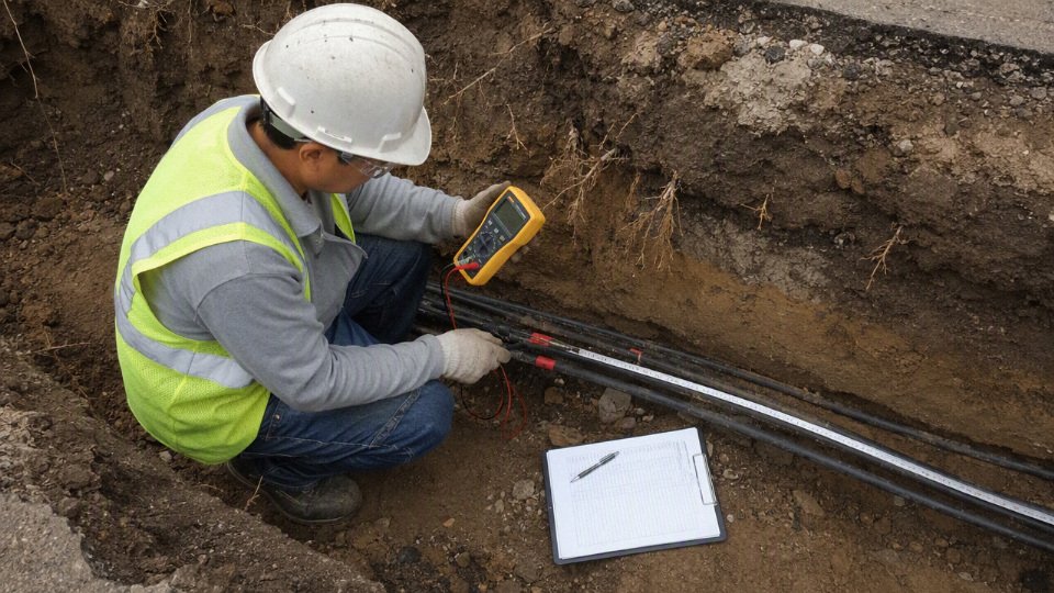
Voltage drop is where many underground runs get expensive
Voltage drop is the loss of voltage caused by conductor resistance. The longer the run and the higher the load current, the larger the drop. Lower voltage at the equipment can mean dim lights, slow gate motors, nuisance trips, hot motor windings, reduced pump output, charger derating, contactor chatter, and poor starting torque.
A common design target is roughly 3 percent voltage drop for branch circuits and 5 percent combined feeder plus branch circuit, unless the project specification, utility, equipment manufacturer, or local rule is stricter. That is a design target, not a universal legal limit for every installation, and the right value depends on what the load can tolerate.
Long underground runs are especially sensitive in applications such as:
- Well pumps and irrigation pumps, where starting current and voltage sag can shorten motor life.
- Automatic gates, where cold weather, stiff gearboxes, and battery chargers add nuisance issues.
- Landscape and site lighting, where voltage drop creates visible brightness variation.
- EV chargers, where sustained current makes energy loss and conductor heating more important.
- Detached garages and outbuildings, where future loads are usually underestimated.
- Remote industrial loads, where a feeder may look acceptable on ampacity but fail during motor start or simultaneous operation.
The mechanism is simple but unforgiving: resistance converts part of the electrical energy into heat along the cable, leaving less voltage at the load. Increasing conductor cross-sectional area lowers resistance, which improves voltage at the equipment and reduces heating losses. The trade-off is higher cable cost, larger reels, bigger terminations, harder handling, and sometimes larger enclosures.
Copper versus aluminum is not just a price choice
Copper gives lower resistance in a smaller cross-sectional area, so it usually wins where terminations are tight, voltage drop is critical, or the run must fit through limited sleeves and risers. It is also more forgiving in small control and branch-circuit work, and many maintenance electricians simply prefer it because lug preparation is less fussy.
Aluminum can be commercially attractive on long feeders because the material cost per ampere is often lower, though pricing moves with the metals market. The penalty is larger conductor size for the same resistance, more termination space, larger bending radius, more attention to compatible lugs, oxide inhibitor where required by the connector manufacturer, and proper torque. I have seen more underground feeder trouble from poor aluminum terminations than from the buried portion of the cable itself.
For procurement, do not compare only price per meter. Compare:
- Delivered cable cost.
- Required upsizing for voltage drop.
- Reel weight and unloading method.
- Minimum bend radius and riser layout.
- Lug, splice, and enclosure compatibility.
- Electrician labor time.
- Maintenance practice and torque verification access.
Single-phase, three-phase, neutral, and harmonics
Single-phase loads draw current through two ungrounded conductors, or through one ungrounded conductor and a grounded neutral depending on the system. Three-phase loads can be more efficient for motors and larger equipment, but only when phase balance is managed. An unbalanced three-phase feeder can put unexpected current on the neutral and increase voltage imbalance at the load.
Neutral sizing deserves attention where there are many line-to-neutral loads, electronic power supplies, LED drivers, variable frequency drives, office equipment, or EV charging equipment. Harmonic currents, especially triplen harmonics in certain systems, can load the neutral more than a buyer expects from a simple nameplate total. Equipment type matters: a balanced three-phase motor load is a different conductor-selection problem from a mixed panel feeding lights, receptacles, controls, chargers, and small drives.
Grounding, bonding, and fault clearing
The equipment grounding conductor is not the same as the grounded conductor, and neither is the same as a grounding electrode conductor. In underground cable work, that confusion causes expensive and dangerous failures.
Keep the roles separate:
- Grounded conductor: normally the neutral in systems that use one.
- Equipment grounding conductor: the fault-current path back to the source or protective device.
- Grounding electrode conductor: connects the grounding electrode system, such as rods or a building steel connection where applicable.
- Concentric neutral: common in some utility and medium-voltage cable constructions; it has a defined function and cannot be casually treated as a generic shield.
- Metallic shield or tape shield: controls electric stress or provides shielding in specific cable designs; termination requirements are product-specific.
Underground feeders must support effective fault clearing. On a long run, conductor impedance may reduce fault current at the remote end. If the available fault current is too low, a breaker may not trip fast enough under certain faults. That verification needs conductor length, size, material, source impedance, transformer data where relevant, protective device curves, and the grounding path design.
Multiple circuits in one trench can change the answer
Several loaded circuits in the same trench, sleeve, or duct bank heat each other. Soil does not remove heat like open air, and poor backfill can make the condition worse. Dry sand, rocky fill, thermal insulation from foam board, or a crowded sleeve through a foundation can all raise operating temperature.
For light residential work, standard code tables and burial rules may be enough. For industrial feeders, multiple EV charging circuits, pump stations, or duct banks, the design may need derating or thermal modeling based on:
- Number of current-carrying conductors.
- Load diversity.
- Burial depth.
- Spacing between cables or conduits.
- Soil thermal resistivity.
- Seasonal moisture changes.
- Backfill material.
- Continuous load profile.
The cheapest cable that passes a basic ampacity check can still be the wrong purchase if it fails voltage-drop, starting-current, utility, fault-clearing, or heat-aging checks. That conclusion stops holding only when the run is short, the load is stable and well defined, the soil and grouping conditions are benign, and the inspection requirements are already confirmed. For anything longer, heavier, or likely to expand, sizing should be treated as an electrical design decision before it becomes a purchasing line item.
Splices and transitions
Most underground cable failures I have seen were not in the middle of a clean cable run; they were at splices, risers, terminations, or places where someone changed from direct burial to raceway. A continuous, correctly sized run is usually the most reliable underground wiring method because it removes water-entry points, reduces inspection ambiguity, and simplifies future fault finding.
Buried splices: avoid them unless there is a real reason
Every buried splice adds three risks:
- Moisture migration through a small nick, poorly sealed connector, or jacket step.
- Mechanical weakness where compacted soil, settlement, or a shovel hit concentrates stress.
- Maintenance uncertainty because the next electrician may not know the splice exists unless records are good.
If a splice is unavoidable, do not treat it like an indoor wire-nut joint wrapped in tape. Use a splice system specifically rated for:
- Direct burial.
- Wet locations.
- The conductor material, including copper, aluminum, or copper-clad aluminum if used.
- The circuit voltage.
- The insulation and jacket type.
- The conductor size and stranding class.
- The installed environment, including soil moisture and possible chemical exposure.
Acceptable systems may include listed direct-burial connectors, resin-filled splice kits, gel-filled kits, heat-shrink sleeves with sealant, molded splice bodies, or manufacturer-approved insulation rebuild kits. The correct choice depends on cable type. A low-voltage landscape cable splice, a 600 V feeder splice, and a shielded medium-voltage splice are not the same job with different packaging.
A buried splice is acceptable just because it is wrapped heavily with electrical tape.False
Tape alone is not a direct-burial splice system. Underground splices need listed or manufacturer-approved components rated for wet locations, direct burial, conductor type, voltage, and cable construction.
Accessible versus buried junctions
A junction box that must remain accessible cannot be hidden under soil, mulch, concrete, or a deck because someone wanted the yard to look clean. Boxes, handholes, and pull points have to be selected and installed for the location they occupy. If the design calls for an underground enclosure, it should be listed or otherwise approved for that purpose, drain or seal as intended, and remain findable after landscaping is finished.
This is where as-built drawings matter. A buried splice without a marker or record turns a two-hour repair into a half-day trenching exercise, usually in bad weather and with production or a pump station already down.
Slack, service loops, and bend control
Leave usable slack, not a tangled coil jammed into wet soil. Slack helps with:
- Final termination after equipment is set.
- Ground settlement after trench backfill.
- Future replacement of a pedestal, pump, gate operator, light pole, or disconnect.
- Thermal movement on long exposed risers.
- Re-termination after a damaged lug or overheated connection.
The trade-off is bend radius and heat. Extra cable should not be folded sharply, crushed against a box edge, or packed so tightly that the jacket is deformed. For larger feeders and shielded cable, the manufacturer’s minimum bend radius is not a suggestion; exceeding it can damage insulation layers or shielding before the circuit ever sees load.
Risers, sleeves, and equipment transitions
The direct-burial portion may be acceptable underground, but once it comes up out of grade it needs physical protection. Use conduit sleeves, rigid guards, long-radius sweeps, bushings, and proper clamps where the cable rises to equipment, walls, poles, or pedestals. I am not fond of flimsy risers in mowing areas; a string trimmer, skid steer tire, or snowplow edge will find the weak spot eventually.
Common transition details to verify include:
- Conduit sleeve material suitable for the exposure.
- Bushings or fittings that prevent jacket abrasion.
- Sealing at the top where water can run into raceway.
- Expansion fittings where temperature movement or structure movement is expected.
- Protection from vehicles, carts, livestock, lawn equipment, and vandalism.
- Correct transition from direct burial cable to individual conductors in raceway, if the wiring method changes.
Building entries, foundations, and terminations
Where underground wiring enters a building, vault, control cabinet, or foundation wall, the job becomes more than just electrical continuity. Seal penetrations against water migration, and where applicable, gas migration. Firestopping may be required when passing through rated assemblies. Metallic raceways and fittings need bonding continuity, and structural penetrations should be coordinated before someone cores through reinforcing steel, waterproofing, or a post-tensioned slab.
At the termination, verify the hardware before landing the cable:
- Lug material and plating compatibility with the conductor.
- Conductor stranding accepted by the lug.
- Torque values from the equipment or connector manufacturer.
- Antioxidant compound for aluminum conductors where required by the connector instructions.
- Correct crimp dies, compression tools, or shear-bolt procedure.
- Shield grounding and stress-control components for medium-voltage cable.
- Jacket removal lengths that do not expose insulation outside the enclosure.
A good cable can be ruined by a bad termination. Over-torque can damage lugs; under-torque creates heating. Wrong crimp tooling may look acceptable until load and thermal cycling expose the problem.
Testing before energizing
Test before backfill when possible, and again before energizing after terminations are complete. The normal commissioning package should include:
- Continuity checks.
- Insulation resistance testing at an appropriate test voltage for the cable and equipment.
- Sheath or jacket integrity testing where applicable and specified.
- Phasing and rotation checks for multi-phase circuits.
- Grounding and bonding verification.
- Torque verification on terminations.
- Photos, test values, cable route records, splice locations, and enclosure identification.
Do not energize an underground run simply because the trench is closed and the schedule is tight. Once a buried defect is under compacted backfill, pavement, landscaping, or a machine foundation, the cost of finding it usually exceeds the cost of testing it properly the first time.
Procurement compliance checks
1. Lock the standard before asking for price
A direct-burial cable quotation is not complete unless the buyer states the exact compliance basis. “Underground cable” is too loose; it lets suppliers offer products that look similar on a datasheet but differ in jacket compound, wet-location approval, flame rating, sunlight resistance, or marking.
Specify, as applicable:
- Cable type and construction, such as direct-burial feeder, armored underground cable, low-voltage power cable, medium-voltage cable, or project-specific utility cable.
- Voltage class, including phase-to-phase and phase-to-ground service assumptions where relevant.
- Conductor material, normally copper or aluminum, and whether compact, compressed, concentric, or sector-shaped conductors are acceptable.
- Insulation material, such as XLPE, EPR, PVC, or another specified compound.
- Jacket material and performance requirements, including PVC, PE, LSZH, sunlight-resistant, oil-resistant, termite-resistant, or flame-retardant properties where the site demands them.
- Direct-burial marking, not just a verbal statement in the quotation.
- Applicable standard or listing, such as UL, CSA, IEC, utility specification, national code requirement, or a project engineering standard.
Do not approve a substitution only because the conductor size and voltage rating match. Underground service life is often determined by the jacket, insulation system, water resistance, and installation limitations, not by copper or aluminum area alone.
2. Request the data that installation crews actually need
Procurement files often contain the easy items — size, cores, voltage, price, delivery — while missing the numbers the contractor needs when the reels arrive. That gap shows up later as damaged jackets, overloaded pulling setups, oversized glands ordered in a rush, or cable that physically will not fit the planned route.
Ask the supplier to provide:
- Conductor size and strand class.
- Insulation thickness and material grade.
- Jacket thickness and jacket material.
- Overall diameter and tolerance.
- Approximate cable weight per unit length.
- Minimum bending radius during installation and after installation.
- Maximum pulling tension and approved pulling method.
- Temperature rating for normal operation and installation handling.
- Ampacity basis, including installation condition, ambient temperature, grouping assumptions, and soil thermal assumptions where relevant.
- Installation limitations, such as direct exposure, riser protection, wet-location rules, or restrictions on pulling through ducts.
The mechanism is straightforward: overall diameter drives gland and conduit transition sizing; bend radius drives trench turns and vault layout; weight and pulling tension drive reel handling, rollers, grips, and pulling equipment. If one of those numbers is wrong, the site team pays for it with labor, not the purchasing department.
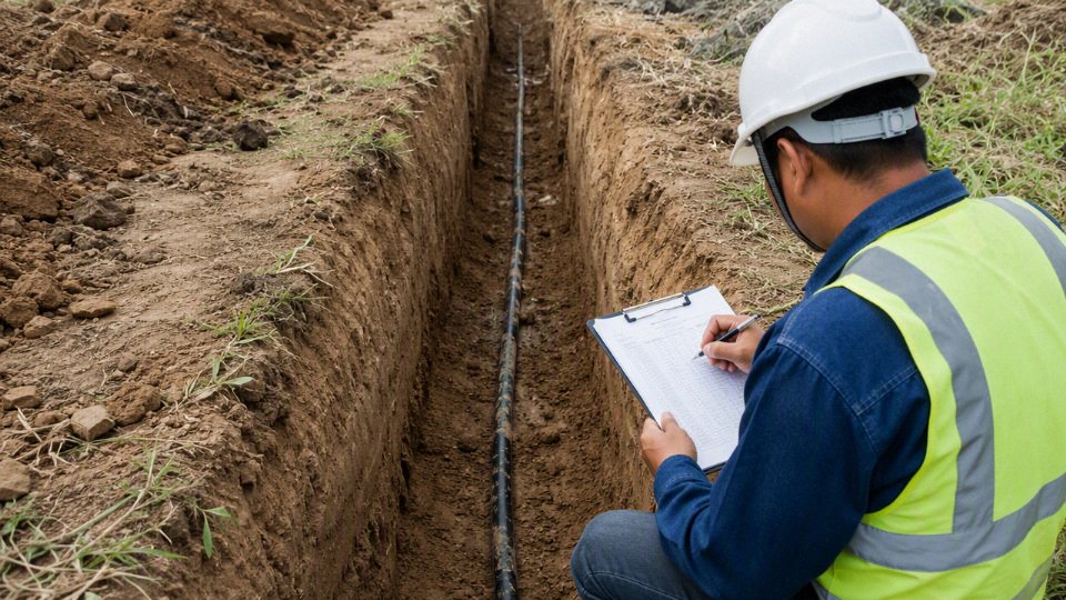
3. Check markings, traceability, and documents against each other
Factory markings should match the purchase order, technical submittal, reel label, and test documentation. I have seen good cable delayed on site because the printed legend used an old project code, and I have seen suspect material accepted because nobody compared the reel label with the approved datasheet.
Verify:
- Reel labels with cable type, size, voltage, length, batch number, and manufacturing date.
- Sequential length marks on the cable where specified.
- Printed cable legends showing the required direct-burial, wet-location, sunlight, flame, or standard markings.
- Batch numbers tied to factory test reports.
- Certificates matching the supplied product, not a generic catalog item.
- Manufacturing date consistent with shelf-life, storage, and project documentation requirements.
- Packaging list, invoice, certificate of origin, and customs documents aligned for international shipments.
For larger projects, make this a hold point before shipment. Correcting a label or document at the factory is cheap; correcting it after a container has cleared port can be miserable.
4. Match the cable to accessories before release
Cable construction affects every termination and joint. Procurement should confirm compatibility for:
- Direct-burial splice kits.
- Heat-shrink, cold-shrink, resin, or gel sealing systems.
- Glands and armor glands.
- Compression lugs and mechanical lugs for copper or aluminum conductors.
- Medium-voltage elbows, stress cones, shields, and grounding kits where applicable.
- Pulling grips, socks, swivels, and approved attachment methods.
- Transition seals where cable rises from earth into equipment, handholes, poles, or buildings.
A thicker jacket may improve mechanical protection but require different glands or larger entry plates. Aluminum conductors may reduce cost and weight, but they need compatible lugs, oxide inhibitor practices where specified, and correct torque discipline. The preferred choice flips when the installed system cost matters more than the cable price per meter.
5. Evaluate the manufacturer, not only the datasheet
A low quote is not useful if the supplier cannot hold extrusion consistency, compound control, conductor quality, or test discipline across long production runs. For direct-burial cable, routine electrical testing and dimensional checks matter because underground defects are expensive to find after backfill.
A buyer should look for:
- Controlled compounding and material traceability.
- Stable insulation and jacket extrusion processes.
- Conductor manufacturing quality, including strand consistency and surface condition.
- Routine electrical testing appropriate to the cable class.
- Quality management systems and inspection records.
- Export packaging experience, including reels, moisture protection, bracing, and document control.
- Technical support that can answer construction and accessory questions before installation.
Shandong Jinda Special Cable Group fits this type of engineered procurement discussion through its five production bases, large-scale manufacturing footprint, integrated research and development, technical support structure, and experience serving international cable projects. That does not remove the need for project approval, but it does make the conversation broader than a commodity size-and-price exchange.
6. Plan bulk logistics before the cable is manufactured
Reel planning should be done with the trench route, pulling direction, site access, and spare strategy in view. Bigger reels reduce joints, which is usually good underground, but they may exceed forklift capacity, laydown space, crane reach, or container unloading limits.
Confirm:
- Reel size, flange diameter, barrel diameter, and gross weight.
- Container loading plan and lifting points.
- Moisture protection for sea freight or outdoor storage.
- Storage limits for sun, temperature, standing water, and reel orientation.
- Cut-length tolerance and measurement method.
- Minimum order quantities.
- Delivery schedule by production lot, not just final shipment date.
- Spare length strategy for repairs, route changes, and termination waste.
Country-specific compliance can still override a technically sound cable. Local electrical codes, utility specifications, customs documentation, label language requirements, and third-party inspection rules may decide whether material is accepted on site. Treat the authority having jurisdiction, utility engineer, or project owner’s approved submittal as the final gate, not the supplier catalog.
Frequently asked questions
Can I bury UF-B cable without conduit?
Yes, UF-B cable is commonly used as a direct-burial cable for residential branch circuits, provided it is correctly sized, buried at the required cover depth, and protected where it emerges from the ground. The above-ground riser into a wall, post, pedestal, or shed is usually the weak point; that exposed section typically needs physical protection, often rigid PVC or another approved raceway.
Local code still controls the job. Wet-location suitability, circuit rating, GFCI protection, soil conditions, and the authority having jurisdiction all matter.
Can I bury THHN wire directly in soil?
No, not for normal installations. THHN or THWN-2 conductors are typically pulled inside conduit; they are not the same thing as a cable assembly listed for direct contact with earth.
THHN or THWN-2 conductors should not be treated as direct-burial cable simply because the insulation is moisture-rated.True
Wet-location conductor insulation does not automatically provide the jacket construction, mechanical protection, or listing needed for direct soil contact. The installation method and product marking must match.
Is conduit better than direct burial?
Conduit is better where the route has mechanical risk, future changes are likely, or the owner wants the option to replace conductors without retrenching. Direct burial can be cheaper and cleaner on long simple runs, especially across landscaping where the cable can be placed at proper depth and left alone.
The trade-off is lifecycle cost. A direct-burial cable may save fittings, bends, glue, and labor today, but if someone later adds a gate operator, cuts the trench with an auger, or needs larger conductors, conduit starts looking inexpensive.
How deep does underground cable need to be?
There is no single universal depth. Typical NEC burial cover requirements fall somewhere around 6 to 24 inches, depending on wiring method, circuit rating, GFCI protection, voltage, location, and whether the route is under a driveway, yard, building slab area, or other traffic exposure.
Do not price trenching from a guess. Confirm the applicable code table, local amendments, inspection preference, and site condition before releasing the work order.
Can I run an underground feeder to a shed without conduit?
Possibly, if the cable is rated for direct burial and the installation meets the required cover, ampacity, grounding, and protection rules. The shed end is where details get missed: building entry protection, a proper disconnect where required, grounding and bonding, and protection from lawn equipment or impact all need to be handled.
A buried feeder is not just “wire in dirt.” Treat it as part of the electrical system serving another structure.
Can outdoor Ethernet or landscape wire be buried directly?
Only if the product is specifically marked for direct burial and outdoor wet exposure. Low voltage does not make soil harmless; water migration, fertilizer salts, freeze-thaw movement, rodents, and shovel damage still destroy cable.
For Ethernet, look for outdoor/direct-burial construction with the correct jacket and shielding or bonding arrangement for the network design. For landscape lighting, use cable rated for the application and expected load, not leftover speaker wire or indoor cord.
Does direct burial cable need warning tape?
Often yes, and even where it is not strictly required, it is cheap insurance. Warning tape or route marking gives the next person with a trenching shovel, fence post auger, or mini-excavator a chance to stop before hitting the cable.
Place it above the cable, not tight against it, so it is encountered first during excavation. On commercial sites, I also like as-built route photos before backfill; six months later, nobody remembers the exact sweep around the drain line.
Can direct-burial cable be pulled through conduit for part of the route?
Yes, it is often used in conduit for protection at risers, driveway crossings, wall entries, or short exposed sections. Check conduit fill, bending radius, pulling tension, heat buildup, and the cable manufacturer’s installation limits.
This is where bulky cable assemblies can be awkward. A cable that lays nicely in a trench may fight you through two tight elbows, especially in cold weather.
What is the biggest mistake in direct burial projects?
The biggest mistake is assuming that any insulated wire is waterproof and suitable for soil contact. It is not.
Before buying or installing, verify:
- Exact cable type and marking
- Direct-burial and wet-location suitability
- Conductor size and ampacity
- Required burial cover
- Riser and transition protection
- Splice method, if any
- Local inspection requirements
Most underground failures I have seen were not caused by copper or aluminum “wearing out.” They started at the wrong product selection, a bad splice, a nicked jacket, or an exposed transition that nobody protected properly.
Verify your cable specification
Underground wiring without conduit is a valid choice only when the cable or conductor is explicitly rated for direct burial and the full installation still satisfies code, soil, mechanical, sizing, and termination requirements. Do not buy from a product name alone. Buy from the marking, the applicable standard, the installation method, and the authority having jurisdiction.
Before issuing a purchase order or cutting a trench, verify five facts:
- Circuit voltage and actual load
- Confirm nominal voltage, phase, continuous load, starting current, and protective device rating.
- Pump motors, gate operators, HVAC equipment, welders, and three-phase loads can change the cable choice quickly because starting current and voltage drop matter more than nameplate running amps.
- Required burial cover
- Typical NEC cover requirements can fall roughly between 6 and 24 inches, depending on wiring method, circuit rating, GFCI protection, location, and local amendments.
- Driveways, landscape areas, farm yards, utility easements, and industrial plants are not treated the same in practice. Get this settled before excavation, not after the inspector sees the trench.
- Soil, water, and damage exposure
- Identify wet clay, corrosive fill, rocky soil, seasonal flooding, rodent activity, vehicle traffic, and future digging risk.
- A cable that survives clean sand under a lawn may be a poor choice beside a pump house where the trench backfill contains crushed stone and scrap metal chips.
- Conductor size and voltage drop
- Check ampacity first, then voltage drop. A common design target is about 3 percent for branch circuits and 5 percent combined feeder plus branch circuit unless the project specification is stricter.
- Long runs often need a larger conductor than the breaker size alone suggests.
- Exact direct-burial marking or standard
- Confirm the cable jacket marking, conductor material, insulation rating, wet-location suitability, and any required listing or project standard.
- If the datasheet and the cable print legend do not agree, stop and resolve it before shipment.
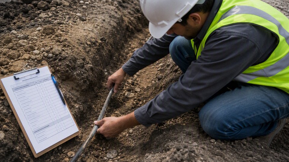
For residential feeders, solar array runs, industrial distribution, pump circuits, utility supply, or bulk cable procurement, involve the authority having jurisdiction, utility, electrical engineer, or licensed contractor before trenching. This is especially important for services, feeders, three-phase equipment, long routes, and sites where a failed underground circuit would shut down production or require cutting concrete to repair.
Think beyond first cost. Direct burial can reduce conduit labor and material, but it is harder to replace later. Partial conduit protection often makes sense at risers, road crossings, building entries, and damage-prone zones. Full conduit costs more upfront, yet it may pay back where future expansion, cable replacement, or downtime risk matters.
If you are preparing a cable specification or purchase inquiry, share the project voltage, conductor size, route length, installation environment, required standard or approval basis, and quantity. Jinda can review those application details against available underground cable construction options and help confirm a suitable specification for residential feeders, solar projects, industrial power distribution, pump circuits, utility supply, or bulk international procurement.