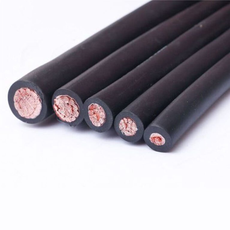
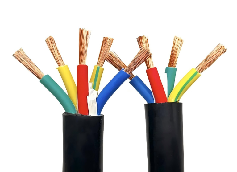
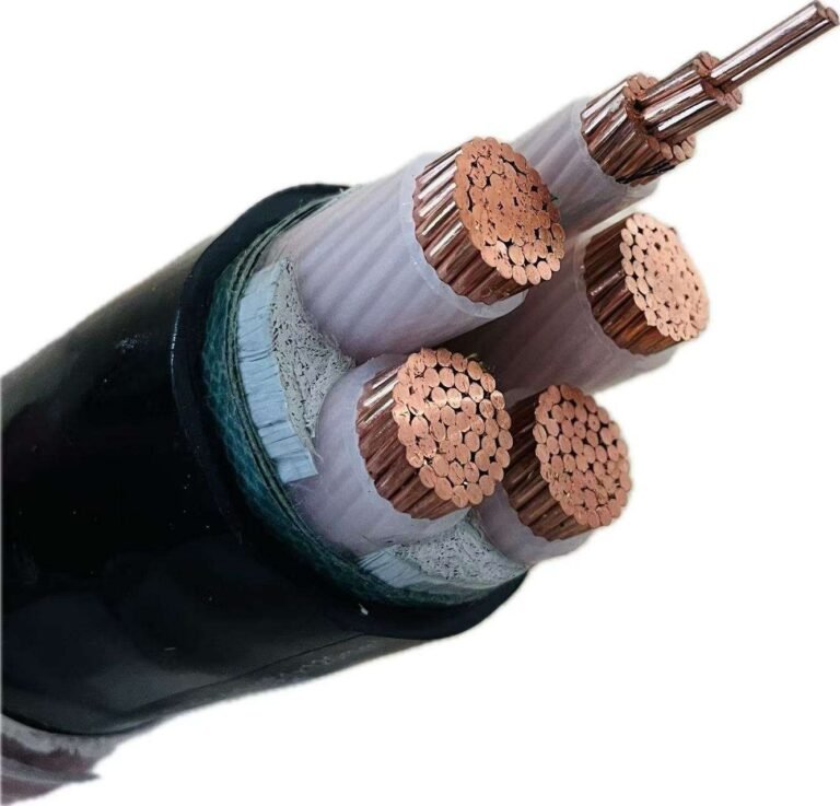
A crowded pipe rack makes it tempting to put the 120V controls and 480V power in the same conduit, especially during a retrofit when every shutdown hour hurts. Get it wrong and the consequence is not just an untidy drawing; it can mean failed inspection, nuisance noise, overheated conductors, or a painful repull through already-loaded raceway. The practical answer starts with voltage-rated insulation, then moves into conduit fill, ampacity adjustment, and circuit-type separation.
Yes, 120V and 480V conductors can usually share the same conduit under NEC 300.3(C)(1), provided every conductor insulation is rated for the highest voltage present, typically 600V in industrial work. That permission does not override conduit fill, ampacity derating, or separation rules for Class 2, communications, instrumentation, and fire alarm circuits.
The trap is that “same pipe” sounds like a simple voltage question, but in the field it becomes a wiring-method, heat, noise, and procurement question. A 600V THHN pull for motor power is one case; a mix of PLC inputs, VFD leads, shielded analog signals, and fire alarm cable is a very different job.
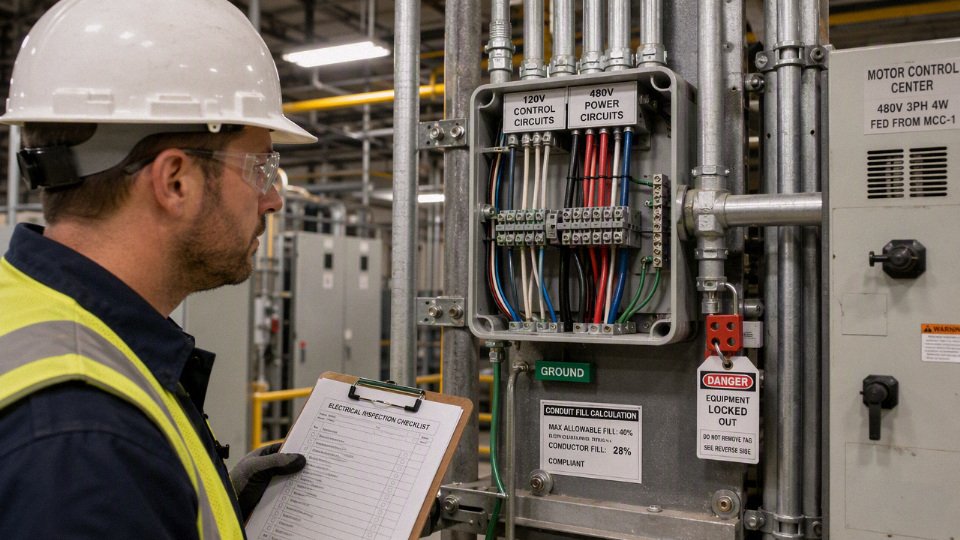
NEC permission and limits
NEC permission is broader than many plants assume: 120V and 480V conductors can occupy the same raceway when the circuits are 1000V nominal or less and every conductor has insulation rated at least as high as the maximum voltage present. That is a code allowance, not a blanket design recommendation, and it does not override fill, ampacity, cable listing, power-limited circuit, or local authority requirements.
NEC 300.3(C)(1) is the core rule most electricians are thinking of when they say “mixed voltages are allowed in the same conduit.” In plain shop language, the raceway does not care whether one circuit feeds a 120V receptacle and another feeds a 480V motor starter, as long as the insulation system on every conductor in that raceway is suitable for the highest voltage exposure in that wiring space.
A direct industrial example is common enough: a 120V branch circuit for a cabinet light or maintenance receptacle is pulled in the same conduit as 480V feeder or branch-circuit conductors. From an insulation-voltage standpoint, that can be acceptable if the 120V conductors are not “120V wire” in the insulation sense, but are 600V-rated conductors such as properly marked THHN/THWN-2 or XHHW-2. The fact that the load is only 120V does not automatically make the conductor insulation only 120V.
A 120V branch-circuit conductor with 600V-rated insulation may share a raceway with 480V conductors under NEC 300.3(C)(1), assuming all other applicable NEC rules are satisfied.True
The permission depends on conductor insulation rating being not less than the maximum circuit voltage present, plus separate compliance with fill, ampacity adjustment, circuit classification, listing, and local enforcement requirements.
Circuit voltage is not the same as insulation rating
A conductor serving a 120V load may be manufactured, listed, and marked with 600V insulation. That is normal in industrial wiring. THHN/THWN-2, XHHW-2, RHW-2, many TC-ER cables, many MC cable constructions, and a lot of industrial control cable are commonly 600V rated, but “commonly” is not good enough for an installation record or an inspection argument.
Check the actual evidence:
- Printed conductor marking on the insulation or cable jacket
- Manufacturer datasheet for the exact part number
- UL, CSA, or other applicable listing information
- Project specification, especially on owner-standard jobs
- Cable schedule or bill of materials, because substitutions happen quietly during procurement
- Panel and equipment documentation, where terminal temperature and wiring type may be restricted
In practice, this catches a lot of small mistakes. A maintenance crew may assume every small-gauge control wire in the cabinet is 600V because the plant usually buys MTW or THHN. Then someone adds a sensor circuit using a 300V-rated shielded cable or a power-limited cable because it was on the shelf. That cable may be perfectly good in a controls-only raceway, but it is not automatically acceptable beside 480V power conductors.
The mechanism is simple: the insulation rating is a tested voltage withstand classification for the conductor construction, not a description of the load it feeds. When a 120V conductor is installed in the same raceway as 480V conductors, the 120V conductor insulation must be suitable for the highest voltage environment it shares. The weak link is not the nominal load voltage; it is the lowest-rated insulation system inside the shared space.
How to read the “maximum voltage” in a 480V raceway
For most industrial plants, “480V” usually means one of two systems:
| System type | What the plant often calls it | Practical insulation question |
|---|---|---|
| 480Y/277V grounded wye | 480V three-phase, 277V to ground | Conductors share a 480V system environment; 600V building wire is normally selected, subject to markings and listing |
| 480V delta, grounded or ungrounded | 480V three-phase | Treat the raceway as containing 480V circuit conductors; verify grounding method, fault behavior, and equipment requirements |
| 120/208V or 120/240V control and utility circuits | 120V loads or receptacles | May share only if insulation and all other rules match the highest voltage present |
The phrase “voltage to ground” can confuse the decision. On a 480Y/277V system, any phase conductor is 277V to ground, but the system is still a 480V nominal system phase-to-phase. On a 480V delta system, the voltage-to-ground relationship depends on the grounding method; a corner-grounded delta is not the same animal as an ungrounded or resistance-grounded system. For the mixed-conduit question, do not downrate the concern just because one conductor only feeds a 120V load or because a wye system measures 277V to ground. Interpret the highest circuit voltage in that wiring space conservatively and document the basis.
Conductors over 1000V nominal are outside this simple 120V-and-480V discussion. Medium-voltage conductors bring different construction, shielding, termination, separation, warning, and installation rules. If a plant is routing 5kV or 15kV conductors near low-voltage controls, that needs a different engineering review, not a casual extension of the 300.3(C)(1) logic.
Cable assemblies can be stricter than individual wire
The rule is easy to apply when you are pulling individual THHN/THWN-2 or XHHW-2 conductors in rigid metal conduit, EMT, PVC, or similar raceway. It gets less tidy with cable assemblies.
A listed cable assembly is not just a bundle of insulated conductors. Its jacket, fillers, shields, armor, drain wires, conductor identification, flame rating, wet-location rating, crush resistance, sunlight resistance, and termination method are part of the listed construction. That listing can narrow what you are allowed to do, even if the individual conductors appear to have adequate voltage insulation.
Watch these cases closely:
- Tray cable and TC-ER cable: Many are 600V rated and suitable for industrial power or control use, but confirm the exact construction, installation method, and whether the cable is being used as permitted by its listing.
- MC cable and armored cable: The assembly rating, conductor type, grounding path, armor type, and permitted locations matter. Do not assume one MC product can replace another just because both contain 600V conductors.
- Multi-conductor control cable: Some control cables are 600V; others are 300V. Shielded analog, encoder, instrumentation, and VFD feedback cables deserve a careful look before sharing routing with 480V power.
- Power-limited Class 2 and Class 3 circuits: These often have separation rules that are not solved merely by using higher insulation voltage. Article 725 requirements can prohibit or restrict mixing with power and lighting conductors.
- Communications, network, instrumentation, and fire alarm circuits: NEC articles covering these systems may require physical separation, barriers, or specific cable types. Ethernet cable next to 480V conductors in the same conduit is not made acceptable by wishful thinking or a zip tie at the panel end.
This is where procurement mistakes show up. A buyer may see “control cable” on two quotes and choose the cheaper reel, while one is a 600V industrial control cable and the other is a 300V instrumentation cable intended for a different wiring class. The receiving dock will not catch that unless the purchase description is tight enough: voltage rating, listing, conductor count, AWG, shield requirement, jacket material, wet/oil/sunlight rating where needed, and permitted installation method.
Code-allowable does not always mean plant-friendly
Even when NEC permits the mixed installation, the design can still be a nuisance. I have seen technically legal conduit become a maintenance headache because every small 120V circuit shutdown required opening a raceway or enclosure that also carried 480V motor power. That changes lockout scope, arc-flash exposure, troubleshooting time, and who is allowed to touch the work under the site’s electrical safety program.
The trade-off is real. Combining circuits can reduce conduit runs, tray congestion, installation labor, and wall penetrations. It can also increase:
- Troubleshooting exposure, because low-voltage work may bring personnel near higher-energy conductors
- Shutdown impact, especially when a simple 120V repair affects a 480V production feeder route
- Noise risk, where sensitive analog or communication circuits run beside switching loads, VFD output conductors, contactor coils, or solenoids
- Future modification risk, because the next electrician may not expect mixed voltages in that pull box
- Derating burden, since multiple current-carrying conductors in one raceway can trigger NEC 310.15 ampacity adjustment
- Conduit fill limits, since NEC Chapter 9 still applies regardless of voltage compatibility
- Heat and pulling damage, especially on long runs with several bends where small conductors are pulled alongside larger feeder conductors
The preferred choice flips depending on the plant. A compact machine skid with short, documented raceways and all conductors clearly marked may justify shared routing. A large food plant, sawmill, wastewater facility, or 24-hour packaging line may prefer separation because maintenance clarity is worth more than saving one conduit. Seasonal condensation in outdoor conduits, oil migration into junction boxes, and “temporary” modifications that stay for ten years all push me toward cleaner segregation when the budget allows.
Local enforcement can be stricter than the baseline NEC reading. State or municipal amendments, owner electrical standards, insurance loss-control requirements, engineering specifications, and the authority having jurisdiction can all narrow the acceptable design. Some owners simply prohibit mixing 120V controls with 480V power in the same raceway except inside listed equipment or short machine-wiring sections. That is not the NEC baseline everywhere, but it is still a binding project requirement when it appears in the contract documents.
For a first-pass compliance judgment, start with NEC 300.3(C)(1), verify the lowest insulation rating in the raceway, then check the rules that do not care whether the insulation rating passed: fill, ampacity adjustment, circuit class separation, cable listing, terminal limitations, and local interpretation. The NEC may open the door, but the installation still has to survive inspection, maintenance, and the next unplanned shutdown.
Circuits that must stay separate
Some circuits should not share a raceway with 120V or 480V power conductors even when every wire in the pipe has a 600V insulation rating. The deciding issue is not only voltage rating; it is circuit classification, listing, noise immunity, life-safety function, hazardous-area rules, and whether the equipment was evaluated for that wiring method.
A 600V insulation rating by itself does not automatically allow every low-voltage, control, communications, fire alarm, or intrinsically safe circuit to be installed with 120V and 480V power conductors.True
NEC permission for mixed voltages under 1000V is limited by other articles that govern Class 2 and Class 3 circuits, communications, fire alarm, hazardous locations, emergency systems, and listed assemblies. Those rules can require separation even where conductor insulation appears adequate.
Class 2 and Class 3 control circuits
Keep ordinary power and lighting conductors out of the same raceway as Class 2 and Class 3 circuits unless a specific code allowance, barrier, listed cable assembly, or equipment construction permits the combination. In a plant, this is where mistakes happen: the wire looks like “just another small control cable,” but electrically and legally it is not being treated as a normal 600V branch-circuit conductor.
Common examples include:
- 24Vdc PLC input and output wiring from Class 2 power supplies
- Proximity sensors, photoeyes, encoder auxiliary wiring, and small valve solenoid control circuits
- Thermostat and HVAC control wiring
- Building automation networks and field controllers
- Security door contacts and access-control power-limited circuits
- Low-energy alarm, interlock, and machine status circuits
The practical reason is partly safety and partly system behavior. Class 2 and Class 3 circuits are limited-energy systems; their wiring rules assume a controlled source and a defined fault-energy envelope. If they are mixed casually with 480V motor feeders or 120V lighting branch circuits, a fault, insulation damage, or termination error can place hazardous voltage onto a circuit that maintenance staff expect to be touch-safe. I have seen cabinets where a blue 24Vdc wire and a brown 480V control transformer primary passed through the same nipple because “both were MTW.” That is exactly the kind of shortcut that later turns into a troubleshooting trap.
The trade-off is convenience versus discipline. Combining conductors can save one conduit run, a few fittings, and some tray space. Separate routing costs more up front, but it preserves circuit identity, simplifies lockout, reduces induced noise, and makes later panel modifications less risky. The “separate them” preference stops being absolute only where the applicable code article and the equipment listing clearly provide a permitted wiring method.
Communications, data, and networked instrumentation
Ethernet, telephone, data, security, camera, and networked instrumentation cables normally need separation from power wiring unless installed under limited permitted conditions, such as listed composite cable, a partitioned raceway or enclosure, or another approved arrangement. Treat a Cat 6 jacket or an industrial Profinet cable as a communications system first, not as a small power cable.
The issue is not just electric shock. Communications circuits depend on controlled impedance, pair twist, shielding, grounding practice, and low common-mode noise. Pulling an Ethernet cable beside a group of 480V motor leads in the same conduit can distort signals, increase packet errors, or create intermittent faults that never appear when the line is tested during shutdown. Those faults are expensive because they look like bad PLC logic, bad switches, bad firmware, or “operator error” before anyone blames the raceway.
Watch these plant-floor combinations closely:
- Ethernet or fiber media-converter power and data cables routed through motor starter gutters
- Telephone or intercom circuits pulled with 120V lighting feeds “for convenience”
- Security and access-control wiring sharing sleeves with panel feeders
- RS-485, Modbus, CAN, or similar low-voltage networks run beside VFD output conductors
- Networked flowmeters, drives, scales, and barcode scanners installed through existing power conduits
Fiber optic cable changes the electrical coupling problem, but not automatically the installation problem. Some fiber cables include metallic armor or strength members. Some listed cable types and plant standards still restrict where they can be run, especially around power distribution equipment, fire barriers, and hazardous areas.
Fire alarm and life-safety circuits
Fire alarm wiring deserves its own review before anybody shares a raceway, box, or wireway with power conductors. Power-limited fire alarm, non-power-limited fire alarm, notification appliance, initiating device, survivability, and riser routing requirements can point to different wiring methods.
Do not treat a red-jacketed cable as “low voltage, therefore flexible.” Fire alarm systems are inspected systems. They may have separation rules, circuit integrity requirements, pathway survivability requirements, and restrictions tied to the listed fire alarm control unit and the adopted code edition. A shared raceway that looks harmless to an electrician trying to finish a tenant improvement can fail inspection or, worse, compromise a life-safety pathway during a fault or fire event.
The same caution applies to emergency lighting controls, smoke control interfaces, elevator recall circuits, fuel system shutdowns, and other life-safety interlocks. The question is not simply “Will it work on a meter today?” It is whether the circuit remains identifiable, protected, and compliant under fault and emergency conditions.
Analog instrumentation and noise-sensitive signals
Analog instrumentation may sometimes be allowed near power wiring by code, but still fail as an engineering installation. Separate routing, shielded twisted pairs, proper drain termination, and clean grounding often matter more than the printed voltage rating on the cable jacket.
Pay special attention to:
- 4 mA to 20 mA transmitter loops, especially long runs from tanks, wells, or outdoor skids
- Thermocouples, where microvolt-level signals make poor routing painfully obvious
- RTDs, particularly 3-wire and 4-wire circuits that depend on lead resistance assumptions
- Load cells and strain gauges, where millivolt signals are easily corrupted
- Pulse and frequency signals from flowmeters, encoders, and tachometers
- VFD speed references, feedback wiring, and analog I/O connected to drives
- High-speed counter inputs and low-level machine sensor wiring
The mechanism is straightforward: changing current in a nearby power conductor creates magnetic coupling; changing voltage creates capacitive coupling. Long parallel runs make both worse. A 4 mA to 20 mA loop may tolerate some noise because the signal current is relatively robust, while a thermocouple or load cell circuit may drift or chatter from interference that would not bother a relay coil. Shielding helps, but it is not magic if the shield is terminated poorly, grounded at the wrong points for the system, or laid in the same conduit as a noisy source for 200 feet.
A representative bad layout is a tank farm conduit carrying 120V solenoid power, 480V pump control, and level transmitter loops back to one marshalling panel. It saves trench space. Then summer thunderstorms, VFD speed changes, and a corroded shield drain create random high-level alarms that nobody can reproduce in the shop.

VFD motor leads are not ordinary 480V feeders
Motor leads from variable frequency drives are among the worst neighbors for 120V controls and low-level signals. They may be 480V conductors by nominal system voltage, but their waveform is not a clean sine wave from a transformer or across-the-line starter.
Fast switching edges from the drive output create high dv/dt. Cable capacitance and motor winding capacitance provide paths for common-mode current. Long motor leads, especially in metal conduit with multiple bends and imperfect grounding continuity, can radiate and couple noise into adjacent conductors. If those adjacent conductors are 120V control circuits, PLC inputs, encoder wiring, or analog feedback, the symptoms can be ugly:
- False PLC inputs when the drive accelerates
- Drive feedback faults at certain speeds only
- Encoder counts missed during high-torque operation
- Analog speed references drifting when another motor starts
- Nuisance trips that disappear when cabinet doors are open or temporary wiring is used
Good practice is usually to route VFD output conductors separately from control and instrumentation wiring, use drive-rated cable or wiring methods recommended by the drive manufacturer, bond properly at both ends where required, and keep line-side and load-side drive wiring organized. The preferred practice can flip in tightly packaged OEM equipment where the entire assembly is listed, barriered, tested, and documented as a system. In field-built plant wiring, I would not assume that.
Special systems that need article-by-article review
Certain circuit categories should trigger a stop-and-check before they share raceways with 120V or 480V power conductors:
- Intrinsically safe circuits
- Hazardous-location wiring and associated apparatus circuits
- Emergency systems
- Legally required standby systems
- Critical operations power systems
- Healthcare essential electrical system circuits
- Elevator, fuel dispensing, crane, hoist, or process safety interlock circuits where special rules apply
- Generator control, transfer switch control, and load-shed wiring tied to emergency or standby operation
Intrinsically safe wiring is a good example of why voltage rating is the wrong shortcut. The installation is designed so a fault cannot release enough electrical or thermal energy to ignite the classified atmosphere. That protection can depend on separation, barriers, grounding, entity parameters, associated apparatus, cable capacitance and inductance, and the control drawing. Running the circuit beside ordinary power wiring because “the insulation is 600V” misses the purpose of the protection method.
The same issue exists inside boxes, wireways, and panels
Raceway rules do not stop at the conduit connector. The same separation logic often applies inside pull boxes, troughs, auxiliary gutters, wireways, junction boxes, MCC buckets, and control panels. In these spaces, the inspection focus shifts to barriers, terminal spacing, wire bending space, conductor support, and whether the enclosure or panel assembly is listed for that arrangement.
A few checks are worth making before approving mixed wiring in an enclosure:
- Are Class 2, communications, fire alarm, or intrinsically safe terminals separated or barriered as required?
- Does the panel listing allow field-installed power and low-voltage wiring in the same compartment?
- Are wire ducts segregated, or are 480V conductors lying across PLC I/O bundles?
- Is there enough bending space for the larger conductors without crushing small signal cables?
- Are shields and drain wires terminated intentionally, not twisted together under a random ground screw?
- Are terminal blocks rated and spaced for the highest voltage present in that section?
- Does the as-built labeling make the circuit class obvious to the next electrician?
This is where procurement and engineering need to talk before the panel is bought, not after it arrives. A cheaper enclosure with one large open wiring bay may cost less on the quote, then consume hours of field labor adding barriers, rerouting cables, and answering inspector comments. A properly partitioned panel or a listed assembly with documented wiring zones often costs more on day one and less by startup week.
Thermal, fill, and voltage effects
A mixed 120V and 480V raceway can be code-permitted and still be a poor design if fill, derating, voltage drop, or fault exposure are ignored. The voltage difference is not the main heat problem; the practical issues are conductor count, load current, raceway capacity, ambient conditions, and what happens during a fault inside a crowded pipe.
Conduit fill is not just a “will it fit?” check
Conduit fill is both a mechanical limit and a heat-management limit. On paper, NEC Chapter 9 fill calculations are straightforward: use the conductor outside diameters or areas from the applicable tables or manufacturer data, then compare them with the allowable raceway fill. In the field, the trouble starts when someone says, “Just add two 120V wires in that 480V conduit; there’s room.”
There may be room at the open end of the pipe, but not through the full run.
Common plant-floor problems include:
- Tight bends at motor control centers or panelboards, especially where the conduit was already pulled hard the first time.
- Older conductors with stiff insulation, which do not slide like new THHN/THWN-2 from a fresh reel.
- LB fittings used as pull points, where the internal bend space is less forgiving than the straight conduit would suggest.
- Mixed conductor sizes, such as large 480V feeder conductors with small 120V control conductors tucked alongside them.
- Long vertical drops, where conductor weight and sidewall pressure matter.
- Wet or dirty raceways, common near washdown areas, cooling towers, outdoor pipe racks, or corroded junction boxes.
The mechanical risk is insulation damage during the pull. Small conductors can be scraped, stretched, or pinched against larger conductors, especially when the large conductors twist through a bend. You may pass megger testing on day one and still have a weakened spot that becomes a nuisance ground fault months later after vibration, heat cycling, or moisture ingress.
From a thermal standpoint, more conductors in the same raceway reduce the ability of each conductor to shed heat. Raceways are not heat sinks in the way people sometimes imagine; they often act more like a thermal blanket, especially in warm ceiling spaces, near furnaces, above injection molding machines, or on outdoor steel exposed to sun. A conduit that is acceptable in a 25°C electrical room may not be acceptable on a mezzanine above a hot process line.
The boundary is simple: if the existing raceway was sized close to its legal fill or ampacity limit, adding even small 120V conductors can turn a compliant 480V installation into a derated or difficult-to-maintain installation.
Current-carrying conductor count can create the hidden penalty
Ampacity adjustment is where mixed-voltage routing often becomes commercially painful. NEC 310.15 requires adjustment when multiple current-carrying conductors are installed together, with the exact adjustment depending on conductor count, installation conditions, and the code edition adopted by the local authority. The calculation is not based on whether a wire is “only control power.” It is based on whether that conductor carries current under normal operation.
For a first-pass review, classify the conductors like this:
| Conductor type | Usually counted for ampacity adjustment? | Practical comment |
|---|---|---|
| 480V phase conductors feeding motors, drives, heaters, or panels | Yes | These are current-carrying conductors. Load profile matters, but they are normally counted. |
| 120V ungrounded branch-circuit conductors | Yes | Even small loads add to the conductor count. |
| 120V neutral in a 2-wire branch circuit | Yes | It carries the same load current as the ungrounded conductor. |
| Shared neutral in a multiwire branch circuit | Depends on circuit type and load | Some neutrals carry only imbalance; others must be counted, especially with nonlinear loads. Verify the NEC rule for the system. |
| Neutral in harmonic-rich 3-phase, 4-wire systems | Often must be treated as current-carrying | Triplen harmonics can add in the neutral rather than cancel. |
| Equipment grounding conductor | No, for normal derating count | It is not intended to carry normal load current. Size it per grounding rules. |
| Metallic raceway used as equipment grounding path | Not a current-carrying conductor | Only acceptable if the raceway is suitable and continuous as an equipment grounding path. |
The advanced trap is that a few small 120V conductors can force derating of much larger 480V conductors. Say a conduit already contains a three-phase 480V feeder with three current-carrying conductors. Adding one 120V 2-wire circuit may bring the count to five current-carrying conductors. That may push the feeder into a lower ampacity adjustment bracket, depending on the applicable NEC table and installation. If the feeder was already selected close to the load requirement, the plant may have just created a capacity problem to save one conduit run.
This is not just code bookkeeping. Conductor heating follows the familiar I²R relationship: current squared times conductor resistance. Voltage rating does not make a conductor run hot by itself. A 600V-rated conductor carrying 5 A on a 120V circuit will usually produce far less heat than the same size conductor carrying 35 A on a 480V load, assuming similar insulation, ambient, and installation conditions. But conductor grouping changes the heat path. The more loaded conductors you pack into the raceway, the less freely each one can reject heat to the surroundings.
There is a trade-off here. Combining circuits can reduce installed cost, reduce conduit congestion, and simplify routing through a crowded ceiling or trench. The sacrifice is ampacity margin, troubleshooting clarity, and sometimes future spare capacity. The preferred choice flips when the added conductors are lightly loaded, the raceway has generous fill margin, the feeder has derating headroom, and the route is accessible for maintenance. It stops being attractive when the 480V circuit is already near its ampacity limit or when the 120V circuit count may grow later.
A low-current 120V circuit can still affect the ampacity of a larger 480V feeder in the same raceway.True
Ampacity adjustment is based on the number of current-carrying conductors and installation conditions, not only on the load current of the added conductors. The final calculation must use the applicable NEC edition and local authority requirements.
Neutral conductors deserve a separate look
Neutrals are where many field calculations go wrong. A 120V neutral is not automatically “free” for derating purposes. In a simple 120V 2-wire branch circuit, the neutral carries the return current, so it is a current-carrying conductor. In a shared-neutral multiwire branch circuit, neutral current may be only the imbalance between ungrounded conductors, but that depends on the system configuration and load type.
The harmonic issue is not academic anymore. Plants with LED lighting drivers, switch-mode power supplies, office loads, VFD control power, battery chargers, and electronic instrumentation can have nonlinear current waveforms. In some 3-phase, 4-wire wye systems, triplen harmonic currents add in the neutral instead of canceling. That means the neutral can run warmer than expected, and treating it as a harmless grounded conductor is a bad habit.
A practical review should ask:
- What loads are connected to the 120V circuit: coils, lights, receptacles, PLC power supplies, instruments, heaters?
- Is the neutral dedicated or shared?
- Are there significant nonlinear loads?
- Is the circuit continuous or intermittent?
- Are multiple 120V circuits sharing one neutral?
- Has neutral loading ever been measured with a true RMS clamp meter under normal production load?
For critical control power, I prefer to be conservative. A nuisance voltage sag on a motor starter coil or safety relay can stop a line faster than a warm feeder ever will.
Voltage drop must be calculated circuit by circuit
Putting 120V and 480V conductors in the same raceway does not make their voltage drop behave the same. Each circuit has its own conductor size, load current, length, power factor, and acceptable voltage at the load.
For the same power level, 480V usually carries much lower current than 120V. That is one reason industrial plants distribute power at higher voltage and step down locally. A 480V motor feeder may tolerate a long run with reasonable conductor size, while a 120V branch circuit over the same distance may suffer noticeable voltage drop, especially with solenoids, contactor coils, control transformers, small heaters, or receptacle loads.
Control circuits deserve special attention. A long 120V run may measure acceptable voltage with no load, then dip when several devices energize together. Coils have pickup voltage requirements. PLC power supplies may ride through a little sag; old ice-cube relays and contactors are less forgiving. If the machine starts only when the panel door is open and the electrician has a meter on it, suspect voltage drop, loose terminations, or both.
Check voltage drop separately for:
- 480V feeders, using actual load current, motor starting behavior where relevant, conductor material, raceway type, and route length.
- 120V branch circuits, especially receptacle or utility circuits added after the original installation.
- Control power circuits, using pickup current, holding current, transformer regulation, and minimum device operating voltage.
- Shared-neutral circuits, where imbalance and harmonic current may affect the neutral voltage shift.
- Long outdoor runs, where temperature changes alter conductor resistance and enclosure conditions.
There is no universal acceptable percentage that fits every plant condition. NEC has informational recommendations for voltage drop in common branch and feeder design, but sensitive controls, motor-starting applications, and customer specifications may demand tighter limits. Use the load’s required operating voltage as the real target, not just a generic percentage.
Fault exposure and raceway integrity
A 120V conductor installed beside a 480V feeder is exposed to the same physical event if that feeder faults inside the raceway. The normal operating voltage may be 120V, but the mechanical and thermal environment during a high-energy fault can be violent: arcing, copper vapor, magnetic forces, damaged insulation, and pressure inside fittings or boxes.
This is one reason insulation quality and installation workmanship matter. Conductors used with 480V systems are commonly 600V rated, such as THHN/THWN-2, XHHW-2, RHW-2, TC-ER, MC conductors, and many industrial control cables, but the actual cable marking and listing must be verified. Insulation voltage rating satisfies only one part of the question. It does not guarantee that the conductor will survive a neighboring fault without replacement.
Available fault current should be part of the decision. A small 480V panel fed from a dry-type transformer may have a very different fault-energy profile than a main switchboard close to a large service transformer. Protective device clearing time matters too. A current-limiting fuse and a slow breaker with poor coordination do not create the same damage envelope.
Grounding and bonding cannot be treated casually
Mixed-voltage raceways still need proper grounding and bonding. Equipment grounding conductors must be sized according to the overcurrent protective device rules, typically NEC 250.122 in U.S. work, and adjusted where required when ungrounded conductors are increased in size. If one equipment grounding conductor serves multiple circuits in a raceway, it generally must be sized for the largest overcurrent device protecting conductors in that raceway, but verify the exact installation against the current code and authority having jurisdiction.
Metallic conduit can serve as an equipment grounding path only if it is installed as an effective, continuous, low-impedance fault-current path. That sounds easy until you inspect older plant areas:
- Rigid conduit with rusted threads near a wash line.
- EMT with loose set-screw couplings after years of vibration.
- Flexible metal conduit used beyond its proper grounding limits.
- Painted or powder-coated enclosures with poor bonding at hubs.
- Outdoor fittings where water has sat in the bottom for years.
- Maintenance modifications where a bonding bushing was removed and never reinstalled.
In corrosive or high-vibration areas, I usually want a copper equipment grounding conductor in the raceway even when the metallic raceway is technically acceptable. It costs less than chasing intermittent ground-fault behavior at 2 a.m. during a production push.
Before approving 120V and 480V in the same conduit, document the calculations instead of treating the route as a field convenience. The review package should include conduit fill, ampacity adjustment, ambient temperature correction, neutral treatment, voltage drop for each circuit, grounding and bonding method, and available fault current at the relevant equipment. That documentation is what separates an intentional mixed-voltage installation from a shortcut hidden inside a pipe.
Noise and reliability risks
A mixed 120V and 480V raceway can be code-compliant and still be a poor controls decision. Clean lighting or receptacle conductors beside a steady 480V feeder are usually uneventful; VFD motor leads, welders, rectifiers, and fast-switched coils in the same path as controls or signals are where nuisance trips, ghost voltage, and hard-to-find faults start showing up.
Electrical noise gets into neighboring conductors through a few plain mechanisms. Capacitive coupling comes from changing voltage: one conductor behaves like one plate of a small capacitor and the adjacent conductor behaves like the other. Inductive coupling comes from changing current: load current produces a changing magnetic field that cuts into nearby loops. Common-mode noise rides all conductors together relative to ground. Ground reference shifts happen when equipment grounding paths carry fault current, leakage current, or high-frequency current, so two cabinets that look “bonded” on a drawing are not at exactly the same potential during an event.
Transient events are the ugly ones because they are short, plant-specific, and often intermittent. A contactor opening a coil, a solenoid valve dropping out, a motor starter chopping through a weak auxiliary contact, or a welder firing on a shared distribution system can put spikes onto conductors that were quiet during commissioning. The meter may show nothing unusual unless it has peak capture or a scope is connected at the right moment.
A code-compliant mixed-voltage conduit is automatically a low-noise design.False
NEC permission mainly addresses insulation voltage and installation safety. Electromagnetic interference, transient susceptibility, maintainability, and manufacturer wiring instructions still have to be checked for the actual loads, cable types, routing length, and terminations.
Which mixed circuits are usually tolerable, and which deserve separation
The difference is not just 120V versus 480V. It is the switching speed, current magnitude, cable length, grounding path, and the sensitivity of the circuit being disturbed.
| Combination in the same raceway | Typical risk level | What usually drives the decision |
|---|---|---|
| 120V lighting branch circuit with a steady 480V feeder | Low to moderate | Mostly fill, derating, identification, and maintenance access |
| 120V control power with ordinary across-the-line motor feeder | Moderate | Coil transients, starter operation, shared grounding, troubleshooting complexity |
| 120V solenoids, relays, alarms, or interlocks with contactor coil circuits | Moderate to high | Induced voltage, leakage through suppression devices, nuisance operation |
| 120V controls with VFD input feeder | Moderate | Harmonics and common-mode noise, usually less severe than VFD output leads |
| Any control or signal circuit with VFD output leads | High | High dv/dt, common-mode current, bearing-current paths, shield termination demands |
| Instrumentation, encoder, thermocouple, load cell, or network cable with power conductors | High | Low signal level, impedance mismatch, data errors, drifting readings |
| Circuits near welders, rectifiers, large SCR heaters, or heavily switched loads | High | Pulsed current, broad-spectrum noise, ground reference movement |
A 120V pilot light circuit is not the same as a 120V input to a safety relay, even if the insulation rating is identical. Ordinary lamps, heaters, and small transformers have enough load impedance and inertia that a few induced volts mean very little. PLC inputs, interposing relays, timer modules, alarms, and electronic solenoid drivers can react to leakage current, spikes, or a floating neutral that would never bother a lamp.
In practice, I get more suspicious when the 120V circuit is part of a permissive chain: guard door interlocks, low-air-pressure proof, overload reset, burner management permissives, pump seal alarms, crane limit switches, or E-stop monitoring through an auxiliary device. A nuisance stop on those circuits is expensive because maintenance has to prove the machine is safe before restart. A nuisance start or false permissive is worse, which is why control reliability often gets treated more conservatively than the bare wiring rule requires.
Why signals suffer before ordinary 120V loads
Analog and digital signal circuits are vulnerable because their useful information is small. A 4-20 mA loop may tolerate industrial noise better than a millivolt thermocouple, but both are trying to communicate a value, not just deliver power. Ethernet, encoder, resolver, RTD, load cell, pressure transmitter, and level probe wiring can all have insulation rated high enough for the raceway and still perform poorly if they are run beside noisy conductors for 80 feet through a tray or conduit bank.
The mechanism is simple but unforgiving. A long parallel run increases coupling length; high source impedance makes the victim circuit easier to disturb; poor shield termination lets noise current find its own return path. If the signal cable shield is landed at both ends without a plan, it may become a parallel grounding conductor. If it is left floating at both ends, it is mostly decoration. The right termination depends on the instrument, drive, PLC input card, and cable construction, so the manufacturer’s wiring instructions matter more than shop folklore.
Digital signals fail differently from analog signals. An analog input may drift, chatter near a threshold, or show a sawtooth pattern that follows motor speed. A digital network may pass acceptance tests and then drop packets when the welder runs, the VFD ramps, or the cabinet fan VFD starts on summer afternoons. That is why the statement “we meggered the cable and it passed” does not close an EMI complaint. Insulation integrity and signal integrity are different problems.
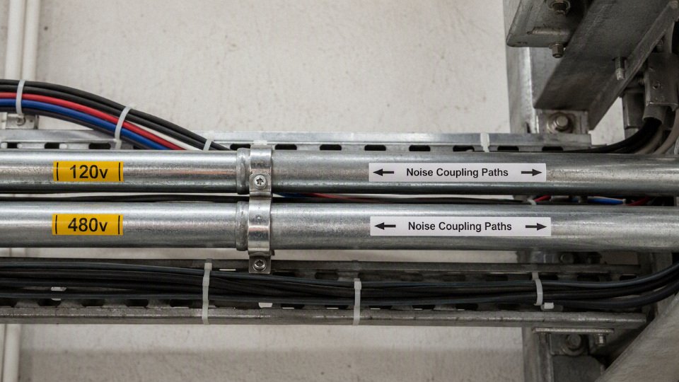
Shielding, grounding, and raceway details that actually matter
Shielding only works when the noise current has a controlled path. A shielded control cable, VFD cable with symmetrical grounding conductors, or metallic conduit can reduce radiated and coupled noise, but each has to be installed as a system. The connector, gland, bonding jumper, enclosure entry, paint removal, grounding bushing, and drain wire termination are not minor hardware details; they decide whether the shield is continuous at high frequency.
Common industrial practices include:
- Use VFD-rated motor cable or manufacturer-approved cable for drive outputs, especially on longer runs or sensitive machines.
- Keep VFD output leads out of raceways containing instrumentation, encoder, network, or low-voltage control circuits.
- Terminate shields as specified by the drive, PLC, or instrument manufacturer; single-point termination is common for some analog signals, while high-frequency drive shields often need 360-degree bonding.
- Bond metallic raceway sections properly, including fittings, flexible sections, and concentric knockouts where required.
- Use grounding bushings or bonding jumpers where raceway continuity may be questionable.
- Avoid using the shield drain as a normal equipment grounding conductor unless the cable and equipment instructions explicitly allow that function.
- Separate noisy and sensitive conductors at cabinet entry and terminal blocks; running them in separate conduits and then bundling them together with a tie-wrap inside the enclosure defeats half the work.
There is a counter-intuitive point here: one shared steel conduit can sometimes provide better shielding than two separate nonmetallic conduits run side by side. The metal raceway can contain electric fields and provide a low-impedance bonding path if properly installed. That does not erase ampacity adjustment, conduit fill, circuit classification, identification, or termination concerns, and it does not make VFD outputs friendly neighbors. The benefit stops holding when the internal conductors themselves are strongly coupling into each other over a long parallel distance or when the sensitive circuit needs isolation by function, not just shielding from outside noise.
Practical separation rules used in industrial layouts
Plant standards usually beat case-by-case arguments. Without written segregation categories, every project turns into a negotiation between the electrical designer, controls engineer, installer, and the person trying to save one conduit run across the mezzanine.
A workable owner standard often separates raceways into categories like these:
- Power feeders and branch circuits: 480V distribution, 120V lighting, receptacles, heaters, and non-sensitive loads.
- Motor outputs: VFD output leads, servo motor cables, dynamic braking circuits, and motor resolver or feedback cables as directed by the manufacturer.
- 120V control circuits: contactor coils, relays, solenoids, permissives, alarms, cabinet power, and control transformers.
- Low-voltage control: 24V DC discrete I/O, safety relay inputs, machine sensors, and valve-bank control wiring.
- Instrumentation: analog signals, RTDs, thermocouples, load cells, flowmeter pulses, pressure and level transmitters.
- Networks and data: Ethernet, fieldbus, remote I/O, vision cables, barcode scanners, and HMI communication.
- Life-safety and special systems: fire alarm, emergency communication, security, and other circuits governed by their own separation rules.
Common routing habits help even when separate raceways are not possible for the whole distance:
- Cross power and signal systems at right angles rather than running them parallel.
- Keep long parallel runs apart; a few inches in a crowded cabinet may be acceptable where 150 feet in a tray is not.
- Put VFD outputs in their own raceway or cable tray zone.
- Do not share pull boxes casually; a pull box can become the place where all separation discipline disappears.
- Label both ends clearly, not just the panel schedule. Future troubleshooting depends on what the midnight shift can identify with a flashlight and a radio call.
- Leave space for future additions, because the second cable pulled into a “temporary” spare conduit is often the one that creates the noise problem.
Maintainability may justify separation even when noise does not
Mixed high- and low-voltage conductors complicate lockout and tagout. If a conduit contains a 480V feeder and a 120V control circuit fed from a different panel or transformer, maintenance may need multiple isolation points before opening a junction box. That adds time, and under production pressure time tends to create shortcuts unless the labeling and procedures are excellent.
Troubleshooting also gets slower. A technician tracing a failed 120V interlock has to treat every box and raceway in that path as containing higher-energy conductors. Future additions become less flexible because the spare capacity in the raceway is not just a physical question; the added circuit may change derating, noise exposure, and shutdown boundaries. Partial shutdown work gets harder too. If the packaging line control circuit shares a raceway with a plant air compressor feeder, neither group will be happy during a planned modification.
For factory owners and technical buyers, the commercial trade-off is straightforward. Combining circuits may save conduit, fittings, tray space, and installation labor up front. Separating them costs more material and coordination, but it usually buys cleaner commissioning, safer maintenance boundaries, easier expansion, and fewer intermittent faults that nobody can reproduce after lunch. The preferred choice flips toward combination only when the loads are electrically quiet, the conductors are properly rated and derated, the route is short or well shielded, the circuits share a sensible shutdown boundary, and the plant has documentation good enough that the next crew can understand what was done.
Cable and conductor selection
For a shared 120V and 480V raceway, specify conductors as if the entire raceway is exposed to the highest circuit voltage present. In most North American industrial work, that means the 120V conductors need 600V-rated insulation when they run with 480V power conductors, not because the load needs it, but because the installation condition does.
Under NEC 300.3(C)(1), conductors of circuits rated 1000V nominal or less may share a raceway if every conductor has insulation rated for the maximum circuit voltage present.True
This is the general NEC rule for mixed-voltage conductors in the same raceway. It does not override separation rules for certain power-limited, communications, fire alarm, instrumentation, or special circuits, and local code adoption should still be verified.
Start with the insulation voltage rating
The purchasing mistake I still see too often is this: someone orders a 120V control cable because the control circuit is only 120V, then routes it in the same conduit as 480V motor conductors. That may fail the basic insulation-rating requirement even if the connected device is a simple pilot light, relay coil, or solenoid valve.
For mixed 120V and 480V conductors in one raceway, the submittal should clearly show:
- Voltage rating: normally 600V minimum for common 480V industrial systems.
- Circuit use: building wire, control cable, tray cable, machine-tool wire, or other listed construction suitable for the wiring method.
- Location rating: dry, damp, wet, oily, sunlight-exposed, corrosive, direct burial, or installed in tray or conduit.
- Temperature rating: insulation rating and the ampacity temperature column actually allowed by the terminals.
- Listing or certification: UL, CSA, ETL, IEC-based certification, or project-specified approvals as applicable.
- Marking: continuous jacket or insulation marking that matches the procurement specification and inspection requirement.
Common 600V-rated conductors used in industrial raceways include THHN/THWN-2, XHHW-2, RHW-2, and other listed building wires selected for the actual environment. USE-2 may appear on job material lists for underground service work, but it is not a universal substitute inside buildings or equipment; verify where it is permitted and whether it has the additional ratings needed for the installed raceway path.
Suitable conductor types are selected by environment, not just voltage
A 600V marking gets you past one gate. It does not prove the cable is suitable for oil, washdown, sunlight, cable tray, machine vibration, or the inside of a hot control cabinet sitting beside a compressor room wall in July.
| Conductor or cable type | Where it is commonly used | Procurement checks before approval |
|---|---|---|
| THHN/THWN-2 | General building wire in conduit; dry and wet locations when marked | Confirm dual rating, 600V rating, conductor stranding, color, and temperature marking |
| XHHW-2 | Feeders and branch circuits where moisture and heat resistance matter | Check insulation thickness, wet-location suitability, and bending space for larger sizes |
| RHW-2 | Rugged feeder and industrial power work; often rubber-based insulation | Confirm compatibility with raceway fill, pulling tension, and environmental exposure |
| USE-2 | Underground service or feeder applications where permitted | Do not assume interior raceway approval unless the cable carries the required additional listing |
| TC-ER cable | Industrial tray and exposed-run applications where allowed | Verify tray rating, exposed-run marking, sunlight resistance, oil resistance, and grounding conductor arrangement |
| MC or armored cable | Plant distribution, equipment drops, and areas needing mechanical protection | Confirm armor type, grounding path, wet-location rating if needed, and termination fittings |
| Control cable | Panel interconnection and industrial controls | Must be rated for the highest voltage in the raceway if mixed with 480V conductors |
| Machine-tool wire | Internal machinery wiring, control panels, and equipment builds | Check MTW or equivalent marking, flexibility, oil resistance, and terminal compatibility |
PVC with a nylon jacket, as used in many THHN/THWN-2 constructions, is a practical choice for ordinary conduit work because it is widely stocked, compact, and familiar to electricians. Cross-linked polyethylene, common in XHHW-2-type insulation, gives better heat and moisture behavior in many feeder applications, though it can be a little bulkier and less convenient in crowded junction boxes. Ethylene propylene rubber is useful where flexibility, abrasion tolerance, and rugged service matter, but it costs more and may not be the first choice for every straight conduit pull.
Low-smoke halogen-free cable is a different discussion. It is not automatically required for a 120V/480V mix, but it may be specified in tunnels, transit facilities, ships, data centers, or enclosed public areas where smoke and acid gas generation during fire are a design concern. If the owner wants LSZH, put it in the cable schedule early; late substitution can affect availability, flame-test documentation, jacket properties, and lead time.
Temperature rating and terminals can quietly reduce ampacity
A conductor may have 90°C insulation and still be limited by a 75°C or 60°C termination. That is not a paperwork nuisance; it changes feeder size, conduit fill, pulling difficulty, heat rise, and sometimes the economics of copper versus aluminum.
In practice, engineers often use the 90°C ampacity column for adjustment and correction calculations where allowed, then land the final allowable ampacity within the terminal temperature limit. The weak link is usually the equipment lug, breaker, contactor, disconnect, terminal block, or device marking. A beautiful 90°C cable does not make a 60°C-rated termination run cooler.
Specify these items clearly:
- Terminal temperature rating for each connected device.
- Ambient temperature assumptions, especially near ovens, rooftops, boiler rooms, foundries, or outdoor cable runs.
- Number of current-carrying conductors in the raceway for ampacity adjustment.
- Whether neutrals are counted as current-carrying conductors under the applicable rule.
- Conductor insulation temperature rating used for correction and adjustment.
- Final ampacity after all derating, not only the catalog ampacity.
The mechanism is simple enough: more current-carrying conductors in the same raceway trap more heat, and higher ambient temperature reduces the conductor’s ability to reject that heat. Mixed 120V controls and 480V power may look tidy on a drawing, but if the raceway becomes crowded, the thermal penalty can force larger conductors or a second conduit. The preferred choice flips when the cost of upsizing wire, fittings, and labor exceeds the cost of separating the runs.
Choose conductor material for the whole termination system
Copper is still the easier industrial default for mixed branch circuits, control power, and equipment wiring. It is compact, conducts well, fits smaller lugs, tolerates repeated maintenance better, and gives fewer surprises when a mechanic opens a panel years later with a flashlight and a torque screwdriver that may or may not still be calibrated.
Aluminum makes commercial sense on larger feeders when the equipment is rated for it and the installer treats it properly. The trade-off is physical size, termination preparation, oxide control, torque discipline, and larger bending space. If a 480V feeder uses aluminum and the 120V controls use copper in the same raceway, the design must still satisfy fill, pulling, terminal, and grounding requirements for the complete conductor set.
Tinned copper is worth specifying in corrosive atmospheres, marine work, wastewater plants, coastal sites, chemical processing areas, and some cooling-tower or fertilizer environments. It does not make a bad enclosure good, but it can slow corrosion at exposed strands and terminations. I would not pay for it in every dry indoor MCC room; I would ask for it before installing ordinary bare copper strands in a salt-laden pump station.
Stranding, flexibility, and industrial cable format
Solid wire belongs in limited places. In industrial conduit, panels, machines, and field devices, stranded conductors are usually more forgiving during pulling, bending, landing, and later service. Once conductor size increases, solid wire is often impractical anyway.
Match the cable format to the installation:
- Use stranded building wire for normal conduit branch circuits and feeders.
- Use fine-stranded or machine-tool wire where vibration, panel routing, or repeated door movement is expected.
- Use tray-rated cable where the wiring method actually includes cable tray and the cable is listed for it.
- Use armored or metal-clad cable where mechanical protection and faster field installation justify the cost.
- Use properly rated control cable for interlocks, relay circuits, and panel-to-machine wiring.
- Use flexible cord only where the code and equipment listing permit cord usage; do not hide ordinary cord in conduit to solve a purchasing delay.
Fine-stranded conductors need compatible terminals. A lug designed for Class B stranding may not properly capture extra-flexible strands, and loose strands at a 480V terminal are the kind of small defect that becomes a nuisance trip, heat mark, or fault investigation later. Ferrules, compression lugs, or listed adapters may be needed depending on the device and conductor class.
Color identification and marking prevent maintenance errors
Mixed-voltage raceways are harder to troubleshoot, so the identification system has to be intentional. Do not rely on “the electrician will know.” The electrician may be a night-shift contractor standing in front of an old enclosure with two circuits locked out and one still energized.
A practical industrial identification scheme should cover:
- Grounded conductors, normally white or gray where applicable.
- Equipment grounding conductors, normally green or green with yellow stripe.
- Ungrounded 480V phase conductors, using the facility’s standard phase colors.
- 120V control power conductors, identified consistently from transformer secondary to field device.
- Control neutrals separated in marking from power neutrals where the system needs that clarity.
- Wire numbers, sleeve markers, heat-shrink tags, or printed legends matching the drawings.
- Panel, conduit, and junction-box labels warning that multiple voltages or multiple sources are present.
Owner-specific color standards matter. Some plants reserve certain colors for 24VDC, safety circuits, UPS power, generator-backed circuits, or foreign voltage inside equipment. Put those rules in the purchase specification before cable production or panel fabrication starts, not after the first shipment arrives.
Supplier documentation to request before releasing the order
For industrial purchasing, the cable quotation is not complete until the technical documents match the installation. Price per meter or per foot is only one line item; rejected cable, relabeling, delayed inspection, and emergency reorders cost more than the small savings from a vague specification.
Request the following documents where relevant:
- Product datasheet showing voltage rating, conductor size, stranding, insulation, jacket, and temperature rating.
- Listing or certification file reference, not just a logo on a brochure.
- Flame rating and applicable test method.
- Wet-location suitability.
- Oil resistance rating for machine, tray, or plant-floor exposure.
- Sunlight resistance for outdoor or tray installations.
- Direct-burial rating if the cable will be buried.
- RoHS, REACH, or similar material declarations when required by the owner or destination market.
- Factory test reports or routine test records for bulk project shipments.
- Drum schedule, length tolerance, marking format, and packaging method.
- Shelf-life or storage guidance for rubber-jacketed or specialty constructions where applicable.
International projects benefit from suppliers that can keep these details consistent across production lots. A manufacturer with integrated production, technical support, bulk packaging coordination, and after-sales engineering communication is easier to manage when a project has several switchgear rooms, multiple contractors, and staged shipments. For a cable group such as Jinda, the useful procurement discussion is not “can you make cable,” but whether the submitted construction, markings, packaging, and documentation match the project’s electrical and inspection requirements across the full order.
Do not substitute low-voltage cable just because the load is 120V
The connected voltage is not the only selection criterion. A 120V relay circuit, receptacle circuit, cabinet fan, heater, light, or solenoid routed with 480V conductors still needs insulation rated for the highest voltage present in that raceway, unless a specific wiring method or separation rule changes the installation.
Avoid these substitutions unless the listing and application clearly permit them:
- 300V appliance wire used inside a conduit with 480V conductors.
- Communication cable pulled beside motor feeder conductors.
- Thermostat, alarm, or Class 2 cable treated as ordinary control wire.
- Flexible cord used as permanent conduit wiring.
- Unmarked import wire with no verifiable listing, temperature rating, or voltage rating.
- Control cable with a suitable voltage rating but no wet-location, oil, sunlight, or flame rating needed for the site.
The cleanest specification is boring but defensible: identify the circuit, voltage exposure, environment, wiring method, termination limits, and required approvals before the purchase order is released. If those items are unclear, do not let a cheaper reel on the shelf become the engineering decision.
Installation checks before energizing
Use this as a field commissioning checklist before putting a mixed 120V and 480V raceway into service. Do not treat it as a paper exercise only; the drawings, labels, boxes, terminations, and test readings all need to agree before anyone closes the covers and releases the equipment.
- Verify the as-built circuits against the approved drawings.
Start with the latest issued drawings, not the first revision sitting in the job trailer. Confirm:- Circuit numbers
- Voltage levels
- Source panels or switchboards
- Breaker or fuse ratings
- Load descriptions
- Raceway route
- Junction box and pull box locations
- Spare conductors and future-use conductors
Mixed-voltage conduit problems often come from field changes: a mechanic adds a 120V cabinet light feed through the “nearest pipe,” or a controls contractor borrows a spare without updating the schedule. That may still be fixable, but it needs to be evaluated as an installed condition, not discovered later during troubleshooting.
- Confirm conductor markings and insulation ratings everywhere you can see them.
Check markings at:- Panel terminations
- Motor control centers
- Pull points
- Junction boxes
- Disconnects
- Control cabinets
- Accessible conduit bodies
For 120V and 480V conductors in the same raceway, every conductor insulation must be rated for the highest voltage present. In most industrial installations that usually means 600V-rated conductors such as THHN/THWN-2, XHHW-2, RHW-2, TC-ER, MC conductors, or similar products specified for the application. If a conductor is unmarked, painted over, heat-damaged, oil-soaked, or inconsistent from box to box, stop and investigate. Do not assume a small control wire is acceptable just because it “only carries 120V.”
Under NEC 300.3(C)(1), conductors for circuits rated 1000V nominal or less may share a raceway if every conductor insulation is rated for the maximum circuit voltage present.True
This is the general NEC rule commonly applied to mixed 120V and 480V power conductors, but the installation must still satisfy other rules such as fill, ampacity adjustment, and separation requirements for certain circuit classes.
Recheck conduit fill using the actual installed conductor list.
The design fill calculation is only useful if the field installation matches it. Count every installed conductor, including:- Spares
- Future circuits
- Field-added control conductors
- Equipment grounding conductors
- Oversized conductors substituted during installation
- Conductors passing through boxes without termination
I have seen fill go from acceptable to questionable because three “temporary” 12 AWG wires were pulled and then left in place for two years. Recalculate against NEC Chapter 9 using the real conductor type and size. Pay close attention at bends, conduit bodies, and existing raceways reused during retrofit work; those are the locations where pulling damage and heat concentration tend to show up first.
Recalculate ampacity adjustment and ambient correction.
Once the final current-carrying conductor count is known, check NEC 310.15 adjustment factors and any ambient temperature correction required by the installation. This matters in mixed 120V and 480V raceways because the 120V conductors may be lightly loaded control or convenience circuits, while the 480V conductors may carry continuous motor, heater, or process loads.The mechanism is simple: more loaded conductors in the same raceway reduce heat dissipation, raising conductor operating temperature. Higher conductor temperature shortens insulation life and can push terminations into a range they were not selected for. The trade-off is installation economy versus thermal margin; combining circuits saves conduit, supports, and labor, but it can force larger conductors or a redesigned route if the final derating becomes severe.
Inspect pulling quality before covers hide the evidence.
Look for:- Insulation nicks or cuts
- Abrasion at conduit entries
- Flattened insulation from excessive pulling tension
- Damage at sharp bushings or locknuts
- Wrong or dried pulling compound
- Conductors forced around tight bends
- Evidence of overheated or chemically attacked insulation
Pulling damage is easy to underestimate on a new job because the megger reading may still look acceptable. A nicked 600V conductor lying against a grounded fitting or another circuit can become tomorrow’s nuisance trip, especially in wet, oily, or high-vibration areas. If the pull was long, heavily loaded, or routed through several 90-degree bends, review pulling tension and sidewall pressure concerns with the installer or engineer of record rather than relying on appearance alone.
Check every termination mechanically and electrically.
Verify:- Lug voltage and temperature rating
- Copper or aluminum conductor compatibility
- Correct conductor size range
- Proper torque using calibrated tools
- Oxide inhibitor where required for aluminum
- Full strand capture with no birdcaging
- Ferrules where specified for fine-stranded control conductors
- Adequate wire bending space
- No mixed conductors under a lug not rated for more than one conductor
Termination quality is where many otherwise code-compliant installations fail in service. A loose neutral on a 120V circuit sharing a raceway with 480V feeders can create confusing symptoms that look like controls trouble. A poorly landed equipment grounding conductor can turn a simple fault into a dangerous touch-voltage event.
Verify grounding and bonding continuity.
Confirm continuity through:- Metallic raceway sections
- Couplings and fittings
- Locknuts
- Bonding bushings
- Flexible metallic conduit
- Equipment grounding conductors
- Panel enclosures and junction boxes
- Transformer or separately derived system bonding points where applicable
Flex connections deserve a close look. A short piece of liquidtight flex to a vibrating motor or pump skid is often where bonding gets weak, especially if the fitting was reused or installed over paint. If the raceway is being used as the equipment grounding path, verify that this is permitted and reliable for the installation conditions; many plants still specify a dedicated equipment grounding conductor because maintenance history has taught them not to trust every fitting forever.
Confirm separation where circuits diverge in boxes and panels.
Mixed circuits may share a raceway and then split into different compartments, terminals, or control enclosures. Check:- Barriers between power and control sections where required
- Covers and dead fronts
- Terminal block voltage ratings
- Labeling of different voltage systems
- Panel directory accuracy
- Separation from Class 2, Class 3, communications, instrumentation, and fire alarm circuits
- Protection against accidental contact during maintenance
This is where a neat conduit installation can still become a maintenance hazard. A technician opening a 120V control box should not unexpectedly find exposed 480V terminals because someone used the box as a convenient splice point.
Perform the electrical tests specified for the project.
Typical pre-energization checks may include:- Point-to-point continuity testing
- Insulation resistance testing with appropriate test voltage
- Phase identification
- Neutral verification
- Equipment grounding conductor continuity
- Ground-fault protection testing where installed
- Control circuit functional testing
- Interlock verification
- Motor rotation checks after safe energization
- Verification of voltage at the load under controlled conditions
Test methods and acceptable values should come from the project specification, equipment manuals, and applicable standards. Do not megger electronic drives, PLC inputs, relays, sensors, surge devices, or instrumentation without confirming they are isolated or rated for the test. That one mistake can turn a clean commissioning day into a parts-expediting problem.
Review lockout and tagout before energization.
A shared raceway can create multiple upstream isolation points. Before release, maintenance and operations should know:- Which disconnects isolate each circuit
- Whether 120V control power comes from a separate panel or transformer
- Whether 480V equipment contains internal control transformers
- Which boxes remain energized when one feeder is locked out
- What labels are needed at junction boxes and panels
If one conduit contains conductors from more than one source, the maintenance procedure must make that obvious before a cover is removed. Labels are cheap; wrong assumptions around mixed voltage are not.
Document test results, deviations, and approvals.
File the final:- As-built drawings
- Circuit schedules
- Conduit fill and ampacity calculations
- Insulation resistance readings
- Continuity and phase test records
- Ground-fault test results where applicable
- Corrective action reports
- Inspector or authority approvals
- Photos of critical terminations or unusual routing

Good documentation is not paperwork for its own sake. Six months later, when a night-shift electrician is tracing a tripped 120V control circuit beside a live 480V feeder, the as-built record may be the difference between a controlled repair and a long, risky shutdown.
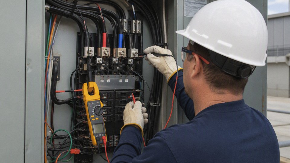
Buyer specification requirements
A good RFQ for mixed 120V and 480V routing must describe the electrical use case, not just ask for “600V cable.” Procurement should lock down voltage rating, insulation system, listing, environment, identification, and substitution rules before price comparison starts. Most bad substitutions happen because the cable looks equivalent on conductor size but is not equivalent in listing, insulation, flame rating, or installed-use approval.
For circuits 1000V nominal or less, NEC 300.3(C)(1) generally allows conductors of different circuits in the same raceway if every conductor insulation is rated for the maximum circuit voltage present.True
This is the core NEC condition for ordinary power and control conductors, but it does not override separation rules for Class 2, Class 3, communications, fire alarm, or other special circuits.
Start the purchase specification with the system context. A supplier cannot responsibly confirm suitability if the RFQ only says “120V control and 480V power in conduit.” State:
- Nominal voltages: for example, 120V control, 480V motor feeder, 480Y/277V, or other system arrangement.
- AC or DC service, including frequency for AC systems, usually 50 Hz or 60 Hz depending on country and plant standard.
- Grounding arrangement: grounded wye, corner-grounded delta, ungrounded, high-resistance grounded, or another engineered system.
- Load type: motor feeder, heater circuit, solenoid control, lighting branch circuit, VFD output, control transformer secondary, or PLC panel wiring.
- Whether the 120V conductors will physically share raceways, trays, pull boxes, junction boxes, or panel wireways with 480V conductors.
That last line matters. A 120V conductor installed by itself may be acceptable in one cable family, while the same conductor placed beside 480V conductors may need a higher insulation rating, different listing, or different routing method. In practice, I like the RFQ to include a one-line routing note such as: “120V AC control conductors may share metallic conduit with 480V AC power conductors; all conductor insulation shall be rated not less than the maximum circuit voltage present.”
Use a structured requirement table so commercial comparison does not bury the engineering requirements.
| RFQ item | What to specify | Why it matters in mixed-voltage routing |
|---|---|---|
| Voltage rating | Minimum insulation voltage rating, commonly 600V for many industrial conductors where allowed by design | Prevents 120V control wire from being supplied as low-voltage signal cable unsuitable beside 480V conductors |
| Conductor size | AWG, kcmil, or mm²; include minimum and project drawing references | Same size does not mean same ampacity after insulation, temperature, and installation method are considered |
| Conductor material | Copper, tinned copper, aluminum, or copper-clad aluminum if permitted | Affects termination compatibility, pulling tension, corrosion behavior, and purchasing substitutions |
| Insulation type | THHN/THWN-2, XHHW-2, RHW-2, TC-ER, MC, control cable type, or project-approved equivalent | Defines wet rating, heat rating, abrasion resistance, flexibility, and code acceptance |
| Temperature rating | 75°C or 90°C insulation rating as required, with terminal temperature limits still respected | Higher insulation temperature may help adjustment calculations, but terminals often limit final ampacity |
| Location rating | Dry, damp, wet, sunlight-resistant, oil-resistant, direct-burial, or tray-rated as applicable | A cable that passes electrically can still fail early from water, UV, oil, or jacket damage |
| Flame performance | UL, CSA, IEC, FT4, VW-1, IEC 60332, LSZH, or project-specific flame/smoke requirement | Many plants standardize flame behavior by area, tunnel, tray, or building code |
| Installation method | Conduit, cable tray, flexible conduit, machine wiring, duct bank, burial, or panel internal wiring | Listing and mechanical construction must match the actual installed condition |
Compliance documentation should be named, not assumed. For North American projects, request UL, cUL, CSA, or other listings required by the contract and local authority. For European or export projects, specify the applicable IEC standards, CE-related declarations where relevant, and any project-specific type tests or factory test reports. CE marking by itself is not a substitute for a recognized cable construction standard; it is a declaration framework, and buyers should ask what standard the cable was designed and tested against.
Environmental data belongs in the RFQ, not in a late email after the drum is already on the water. Include:
- Indoor or outdoor installation.
- Direct sunlight exposure.
- Wet location or intermittent washdown.
- Oil, coolant, hydraulic fluid, or cutting fluid exposure.
- Chemical exposure, including acids, alkalis, solvents, cleaning agents, and fertilizer dust if present.
- Abrasion risk at tray edges, conduit entries, drag chain sections, or machine frames.
- Vibration near motors, presses, crushers, compressors, or mobile equipment.
- Tray use, conduit use, duct bank, burial, or flexible connection.
- Ambient temperature range, including roof runs, furnace areas, cold rooms, and seasonal outdoor extremes.
- Hazardous-location constraints, if classified areas are involved.
The mechanism is simple: insulation and jacket materials age by heat, moisture, oil absorption, UV exposure, and mechanical damage. A PVC/nylon building wire that is fine in dry conduit may be the wrong purchase for an oily machine tool area or outdoor cable tray. The trade-off is cost and availability. A heavier industrial cable package with oil resistance, tray rating, sunlight resistance, and stronger identification costs more per meter, but it reduces field exceptions, emergency substitutions, and mixed inventory across sites. That preference stops holding when the installation is tightly defined, indoors, dry, protected, and governed by a local standard cable already approved by the engineer and authority.
Identification requirements are a procurement control, not cosmetic detail. Specify:
- Conductor color coding by project standard.
- Printed legend showing voltage rating, insulation type, conductor size, listing, and manufacturer identification.
- Sequential meter or footage marking.
- Circuit tags or core numbering for multi-core control cable.
- Drum labels with project name, cable type, length, purchase order, batch number, manufacturing date, and destination area.
- Packaging by construction phase, building, line, skid, or plant area so electricians are not cutting from the wrong drum on night shift.
Be explicit that 120V control conductors are not to be substituted with low-voltage instrumentation, alarm, data, or generic signal cable when they will share raceways with 480V conductors. Some signal cables are excellent products in the right tray or panel, but they may not have the insulation voltage rating, listing, jacket construction, or separation approval needed for this installation.
Substitution control should be written as a hard commercial condition: no alternate cable may ship until the buyer, engineer, or designated technical approver reviews the datasheet and compliance documents. A matching conductor size alone is not approval; voltage rating, listing, insulation, temperature rating, flame performance, and environmental suitability all have to match the installed service.
For multi-plant or international procurement, buyers often prefer integrated manufacturers because repeat cable packages need more than a quotation. A group with R&D, controlled production, technical support, and after-sales service is better positioned to keep compound selection, markings, documentation, drum packaging, and project communication consistent across countries. Shandong Jinda Special Cable Group Co., Ltd., established in 1987, represents that type of integrated supply model, with multiple production bases, large manufacturing capacity, and export experience across many markets. The engineering buyer still has to verify standards and listings for the destination project, but a controlled manufacturer is easier to audit than a trading chain with unclear factory responsibility.
Frequently asked questions
Can 120V and 480V wires be in the same conduit?
Yes, in many standard power and control situations they can share a raceway, provided every conductor has insulation rated for the highest voltage present and no special separation rule applies. Under NEC 300.3(C)(1), circuits rated 1000V nominal or less may occupy the same raceway when the insulation condition is satisfied.
120V and 480V conductors are not automatically prohibited from sharing conduit under the NEC.True
NEC 300.3(C)(1) permits conductors of circuits rated 1000V nominal or less in the same raceway when every conductor insulation is rated for the maximum circuit voltage present, subject to other applicable rules.
That code permission is only the first gate. You still have to check conduit fill, ampacity adjustment, circuit classification, maintenance safety, and owner standards. A legal installation can still be a bad maintenance decision if a technician has to troubleshoot a 120V pilot circuit in the same pull box as live 480V feeder conductors.
Does a 120V wire need 600V insulation near 480V wires?
If the 120V conductor shares the same conduit, wireway, or enclosure section with 480V conductors, it generally needs insulation rated at least for the highest voltage present. In North American industrial work, that commonly means 600V-rated insulation such as THHN/THWN-2, XHHW-2, RHW-2, TC-ER, MC, or a listed control cable suitable for the installation.
Do not assume that a “control wire” is automatically acceptable. Some machine-internal, appliance, thermostat, alarm, or communication cable may have a lower rating or a listing that does not fit the raceway use. Check the jacket marking, datasheet, and project specification before approving substitutions.
Can 24V control wiring share conduit with 480V?
Usually not without a very specific permitted wiring method. Many 24V circuits are Class 2, Class 3, instrumentation, analog signal, encoder, network, or communication circuits, and those categories often have separation rules that are stricter than ordinary 120V control wiring.
The practical problem is not only voltage rating. A 24V sensor loop may tolerate very little induced noise, and a Class 2 power-limited circuit may lose its classification if it is mixed incorrectly with power conductors. In a plant, I would normally route 24VDC I/O, Ethernet, thermocouples, load cells, and pulse signals separately from 480V unless the panel design, cable construction, and code article clearly support the combined route.
Can 120V controls share conduit with VFD output leads?
It is usually poor practice, even if a narrow code path appears possible. VFD output conductors carry fast switching edges, high dv/dt, common-mode noise, and leakage currents that can couple into nearby control wiring.
The result is the kind of fault that wastes shifts: nuisance input changes, flickering pilot lights, analog drift, failed proximity switch diagnostics, or a drive trip that only appears when the motor is loaded. Many drive manuals and project standards require VFD motor leads to be segregated, shielded, or routed in dedicated metallic raceway. Follow the current drive manufacturer instructions and the engineering specification.
Do neutrals count for conduit derating?
Sometimes. A neutral is counted as a current-carrying conductor when it carries unbalanced current, and it may also count in circuits with significant harmonic current, such as certain 3-phase, 4-wire systems serving nonlinear loads.
The exact answer depends on the circuit arrangement, load type, and applicable NEC 310.15 rules. Do not treat all neutrals as “free” in a mixed conduit calculation. That shortcut can undersize conductors in panels feeding drives, LED power supplies, computers, UPS equipment, and other nonlinear loads.
Does the equipment grounding conductor count for derating?
Generally no. Equipment grounding conductors are not normally counted as current-carrying conductors for ampacity adjustment because they carry current only during fault or abnormal conditions.
They still count for conduit fill because they occupy physical space. In tight retrofits, the ground wire can be the difference between an easy pull and a conduit that is already overfilled by calculation.
Can different panels feed circuits in the same conduit?
It may be possible, but it needs careful review. Mixing sources creates identification and maintenance hazards, especially where one disconnect does not de-energize every conductor in the raceway or junction box.
Check at least these items:
- Conductor and circuit identification at both ends
- Whether simultaneous disconnecting is required
- Lockout/tagout procedure for all sources
- Shared neutral or multiwire branch circuit rules
- Emergency, standby, UPS, or life-safety source separation
- Owner rules on keeping MCC, panelboard, and control power circuits apart
This is one of those cases where the drawing may look clean, but the electrician opening a gutter at 2 a.m. inherits the risk.
Is conduit fill based on voltage?
No, conduit fill is based mainly on the physical size and number of conductors compared with the raceway size. Nominal circuit voltage is not the fill calculation driver.
Voltage can affect fill indirectly because insulation type and cable construction change outside diameter. A 600V XHHW-2 conductor, a shielded VFD cable, and a multi-conductor control cable of the same copper size may occupy different space. Use actual manufacturer dimensions when the raceway is crowded, not a casual wire-size assumption.
Can existing conduit be reused for added 120V wiring?
Only after a proper field check. Existing conduit is often less available than it looks on a drawing, especially after years of undocumented maintenance additions.
Before reusing it, verify:
- Existing conductor voltage ratings
- Raceway fill using actual conductor counts and sizes
- Ampacity adjustment after adding current-carrying conductors
- Condition of insulation, fittings, seals, and pull boxes
- Whether any circuit is Class 2, instrumentation, fire alarm, communication, or safety-related
- Pulling tension and damage risk during the new installation
- Shutdown plan and lockout boundaries
If the conduit contains old cloth-covered wire, heat-darkened THHN, damaged insulation, or mystery conductors with missing labels, stop and investigate before pulling anything new.
Who has final approval?
Final acceptance rests with the authority having jurisdiction, the project engineer of record, the owner’s specification, and the local code requirements in force for that installation. The supplier can confirm cable ratings and construction, but the installed wiring method must be approved in context.
For procurement, that means the purchase order should not say only “600V cable.” It should state the installation environment, raceway sharing condition, applicable standards, voltage class, conductor insulation, shielding requirements if any, and documentation needed for inspection.
Your code and cable verification
The safe answer is not “yes” or “no”; it is a short verification chain. Ordinary 120V power or 120V control conductors can often run with 480V conductors when all conductors are properly rated, filled, derated, and identified, but low-energy, signal, life-safety, VFD, and special systems deserve a separate review before anyone pulls wire.
Use this sequence before the purchase order is released, not while the electrician is standing beside a half-filled conduit with a fish tape in hand:
- Identify every circuit in the raceway
- 120V branch power
- 120V control power
- 480V motor feeder or branch circuit
- Control transformer secondary
- Interlock, permissive, or pilot-device wiring
- Spare conductors, if they will be landed later
- Confirm the circuit classification
- Treat normal power and control wiring differently from Class 2, Class 3, communications, instrumentation, fire alarm, and other limited-energy systems.
- Do not assume “it is only 24V” means it can share the pipe. The circuit class and installation rules matter more than the number printed on the relay coil.
- Verify conductor insulation voltage rating
- For mixed 120V and 480V conductors, the practical industrial norm is usually 600V-rated insulation, such as common THHN/THWN-2, XHHW-2, RHW-2, TC-ER, MC, and many 600V control cables.
- The insulation rating must cover the highest circuit voltage present in that raceway, not just the conductor’s own operating voltage.
Under NEC 300.3(C)(1), conductors of circuits rated 1000V nominal or less may occupy the same raceway if every conductor has an insulation rating at least equal to the maximum circuit voltage present.True
This is the general permission, but it does not override separate rules for Class 2, Class 3, communications, fire alarm, instrumentation, or manufacturer-specific equipment wiring requirements.
- Check raceway fill
- Use NEC Chapter 9 methods and the actual conductor outside diameters.
- Do not let purchasing substitute a thicker cable construction after engineering has already calculated fill. A small OD increase on multi-conductor cable can turn an easy pull into a damaged-jacket problem.
- Calculate ampacity adjustment
- Count current-carrying conductors under NEC 310.15.
- Heat is the quiet failure mechanism here: more loaded conductors in one raceway raise conductor temperature, which can force larger wire, fewer circuits, or a separate conduit.
- Neutrals, control conductors, and non-simultaneous loads need proper classification rather than blanket counting or blanket ignoring.
- Evaluate noise and equipment behavior
- VFD output conductors, encoder wiring, analog instrumentation, Ethernet, and sensitive sensor wiring should not be casually grouped with 480V power.
- The trade-off is simple: shared conduit saves steel, supports, labor, and penetrations, but it can cost you troubleshooting time, nuisance trips, unstable signals, and harder lockout verification.
- Confirm maintenance safety and labeling
- Label both ends of the raceway and every enclosure entry.
- Show mixed voltages on the drawing.
- Make sure the disconnecting means, panel schedule, and wire markers do not leave a technician assuming a 120V control box is dead while 480V conductors remain energized inside the same route.
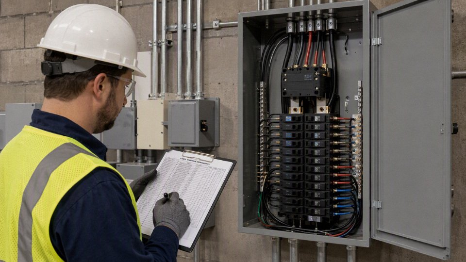
The lowest-risk projects settle segregation, insulation ratings, jacket type, markings, and documentation during design and procurement. Field judgment still matters, but the job site is a poor place to discover that a control cable is not rated for the highest voltage in the conduit, or that an instrumentation pair should never have been routed beside a motor feeder.
For procurement, create a cable schedule that identifies each cable or conductor type by:
- Voltage and circuit function
- Insulation voltage rating
- Conductor count and conductor size
- Raceway group or tray route
- Wet, dry, outdoor, oil-exposed, UV, buried, or high-temperature environment
- Shielding, armor, or tray-rating requirements
- Applicable standards and destination-country certification needs
- Required test documentation, markings, and packing requirements
For industrial projects requiring 600V-rated building wire, control cable, tray cable, armored cable, or custom cable packages, send the cable schedule, operating environment, applicable standards, and destination-country requirements for review before ordering. Jinda can review project specifications, support bulk cable procurement, and align manufacturing documentation with international project requirements so the supplied cable package matches the electrical design rather than forcing substitutions in the field.