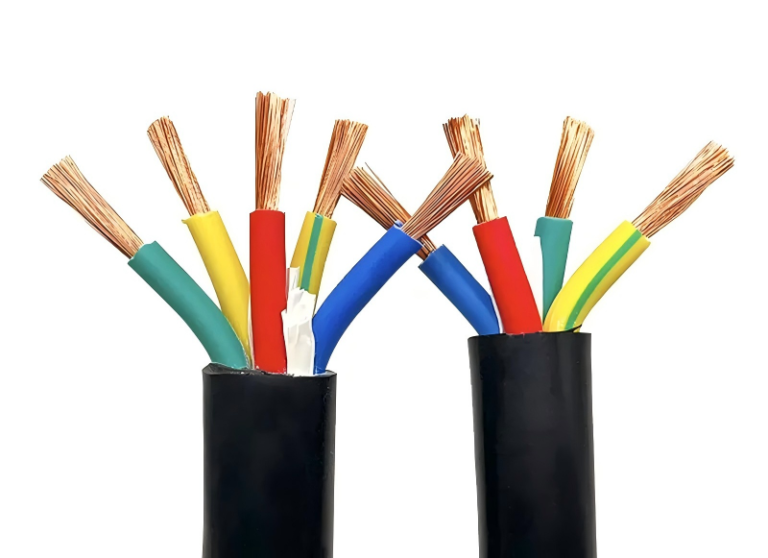
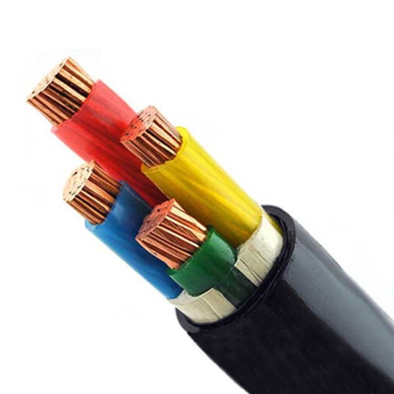
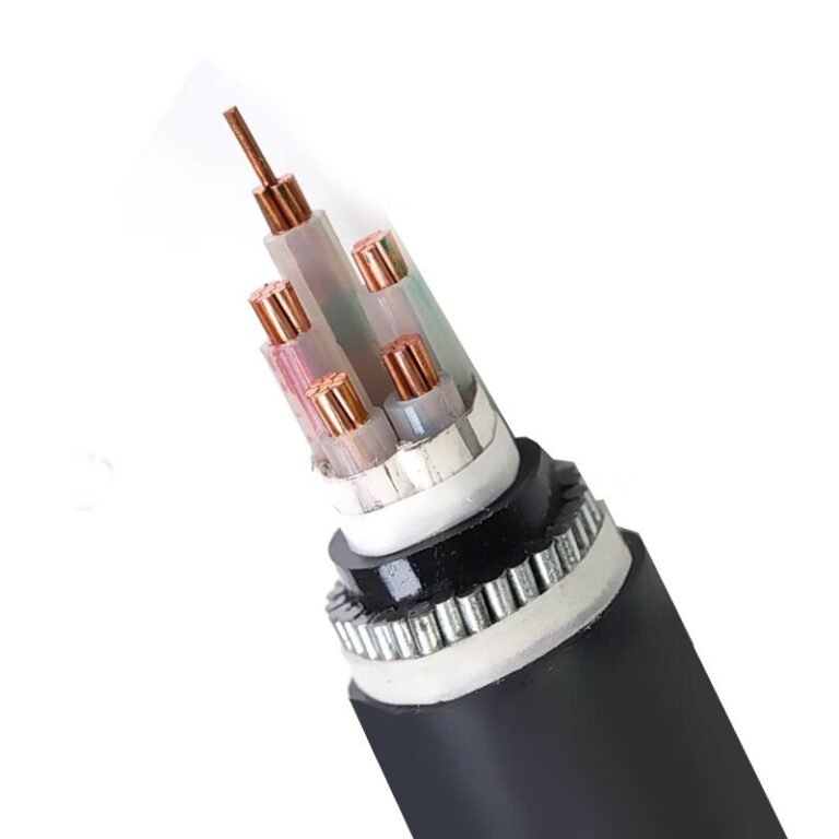
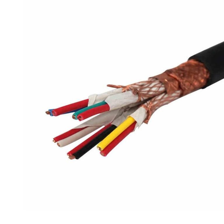
A panel nameplate says 480 V, a meter reading shows something else, and suddenly the buyer, electrician, and production manager are not talking about the same system. That confusion can lead to wrong motor starters, undersized cable, nuisance trips, overheated equipment, or a rejected shipment. The fix starts with separating nominal system voltage from measured voltage, then checking the supply configuration against accepted voltage ranges.
Three-phase power is normally described by its nominal voltage, not an exact meter reading. In North American low-voltage systems, common values include 208Y/120 V, 240 V delta, 480Y/277 V, and 600Y/347 V. A reading of 408 V is not the standard name for a 480 V system and should be investigated.
The tricky part is that both numbers can appear in the same conversation for legitimate reasons: line-to-line versus line-to-neutral measurement, wye transformer math, utility tolerance, voltage drop under load, or a simple transcription error on a purchase specification. Before anyone orders cable, switchgear, motors, or a transformer, the measurement points and the nominal service need to be pinned down.

Nominal voltage versus measured voltage
A three-phase system can be correctly called 480 V even if your meter reads 474 V, 486 V, or another nearby value at a particular moment. “480 V” is the nominal system class used for design, equipment nameplates, cable insulation selection, and service description; it is not a promise that every point in the plant will sit at exactly 480.0 V all day.
Nominal voltage is the language that keeps the electrical design tied together. A motor starter, molded-case breaker, VFD, cable schedule, transformer secondary, and utility service agreement all need a named voltage class. In North American low-voltage work, common three-phase utilization systems include 208Y/120 V, 240 V delta, 480Y/277 V, and 600Y/347 V. Those names tell the engineer what equipment family to select and what insulation, interrupting rating, clearances, and utilization voltage range need to be checked.
A handheld meter reading is a snapshot. It depends on where the probes are placed, what the load is doing, transformer tap position, feeder length, conductor size, connection condition, and sometimes what the utility voltage is doing on a hot afternoon when every rooftop unit in the industrial park is running.
For many low-voltage systems, ANSI C84.1 Range A is commonly used as a service-voltage reference and is generally within plus or minus 5 percent of nominal, subject to the exact system and point of measurement. That does not replace the local utility tariff, project specification, or equipment manual, but it gives a useful sanity check. On a 480 V system, plus or minus 5 percent is roughly 456 V to 504 V. A measurement around 408 V is not a small normal drift from 480 V.
408 V is approximately 15 percent below 480 V.True
The difference is 72 V; 72 divided by 480 equals 0.15, or 15 percent. That is well outside a typical plus or minus 5 percent service-voltage expectation for many low-voltage systems.
A healthy 480 V service might read a little high at the main switchboard during light load, especially if the transformer taps were set to support voltage during heavier production. It might read a little low at a motor control center during peak load, and lower still at the terminals of a large motor at the end of a long feeder. That is normal electrical behavior. Current flowing through conductor impedance causes voltage drop; the more current and the longer or smaller the conductor, the greater the drop. Motor starting makes the effect worse for a few seconds because inrush current can be several times running current.
What should not be brushed off is a steady 408 V reading on a circuit assumed to be 480 V. At 408 V, the first working assumption should be “something is wrong or misidentified,” not “this is just how 480 V looks in the field.” In practice, I would want to know exactly where that reading was taken before blaming the utility or the cable. A voltage measured at the service entrance means something very different from voltage measured across a motor while a conveyor is jammed and a compressor starts on the same feeder.
Typical measurement points create a lot of confusion:
| Measurement point | What the reading usually tells you | Why it may differ from another point |
|---|---|---|
| Utility service entrance or main switchboard | Incoming service condition and transformer secondary voltage | Least affected by plant feeder voltage drop, but still affected by utility regulation and transformer taps |
| Main distribution panel or MCC bus | Voltage available to groups of loads | Drops with upstream feeder impedance and shared load current |
| VFD input terminals | Voltage actually supplied to the drive | May show sag during high plant load; line reactor or feeder impedance can affect readings |
| VFD output terminals | Not the same as normal sine-wave supply voltage | PWM output can confuse ordinary meters; verify with the drive manual and proper instruments |
| Motor terminals | Voltage available to the motor under actual running or starting conditions | Includes feeder drop, starter contact resistance, cable length, and load current |
| Far-end receptacle or machine disconnect | Local utilization voltage | Often where undersized branch circuits, loose lugs, or long runs show up first |
That table matters because two people can argue about “the plant voltage” while both are reading correctly. The maintenance technician may see 462 V at a motor during a hard start. The electrician at the main switchboard may see 487 V at the same moment. Neither meter is lying; they are measuring different parts of the voltage-drop chain.
For a 480 V three-phase wye system, the line-to-neutral value is also part of the diagnosis. The engineering relationship is:
- Line-to-line voltage = line-to-neutral voltage × 1.732
- On a nominal 480Y/277 V system, 277 V × 1.732 is approximately 480 V
So if someone measures about 408 V line-to-line and about 235 V line-to-neutral, that looks like a wye system operating well below the expected 480Y/277 class. If someone measures 408 V only between certain points, or uses one phase-to-ground reading and assumes the rest, the interpretation may be wrong. I have seen avoidable purchasing mistakes start with exactly that kind of partial measurement: one hurried reading, no phase-to-phase check, no confirmation at the service gear nameplate.
A steady 408 V reading on equipment expected to be supplied from a 480 V system can point to several different problems:
- Incorrect transformer tap setting. A dry-type transformer or service transformer may be tapped for a different primary condition than the one actually present.
- Severe feeder voltage drop. Long runs, small conductors, high load current, and poor power factor can combine badly, especially on expanded lines where extra machines were added after the original installation.
- Overloaded distribution equipment. A feeder that was acceptable five years ago may now be carrying welders, compressors, ovens, or drives that were never in the original load calculation.
- Poor connection or failing termination. A loose lug, oxidized aluminum termination, heat-damaged breaker jaw, or tired contactor can create local voltage loss and heat. This is where an infrared scan often earns its keep.
- Utility-side issue. Low primary voltage, regulator trouble, or service transformer loading can pull the whole facility down. Confirm at the service point before assuming it is internal.
- Wrong system assumption. The site may not actually be 480 V. Some facilities have mixed 208 V, 240 V delta, 480 V, and step-up or step-down transformers. Old panel labels are not evidence; they are hints.
- Measurement error. Wrong meter setting, poor leads, averaging meters on distorted waveforms, or measuring VFD output with the wrong instrument can produce misleading numbers.
There is a trade-off in how aggressively a plant designs around voltage variation. Larger conductors, shorter feeder routes, properly selected transformers, and local distribution close to the load reduce voltage drop and improve motor starting. They also cost more in copper or aluminum, conduit, tray space, switchgear size, and installation labor. The preferred choice flips when downtime, nuisance trips, hot motors, or rejected product cost more than the heavier electrical infrastructure. For a lightly loaded warehouse fan circuit, a modest drop may be acceptable. For extrusion, refrigeration, pumping, CNC spindles, or synchronized production equipment, low voltage can turn into scrap, drive faults, overheated windings, and ugly troubleshooting at 2 a.m.
Cable selection follows the nominal system class, not every meter fluctuation. A cable is selected by looking at:
- System voltage class, such as 480Y/277 V or 600Y/347 V
- Required insulation voltage rating under the applicable standard
- Ampacity after installation corrections for ambient temperature, grouping, tray or conduit fill, and soil conditions for buried cable
- Short-circuit and ground-fault exposure until protective devices clear
- Conductor material, termination compatibility, bending radius, pulling tension, and environmental exposure
- Project specifications, local electrical code, utility rules, and equipment manufacturer requirements
That distinction prevents two opposite mistakes. One mistake is under-specifying cable because the meter happened to show only 408 V during a bad operating condition. The other is overreacting to a transient high or low reading and changing insulation class when the real problem is voltage regulation, conductor sizing, or a loose termination. Cable voltage rating is chosen for the electrical system and installation duty; voltage-drop correction is handled through conductor sizing, circuit layout, transformer/tap review, and load management.
The boundary is worth stating plainly: if the site truly has a special distribution arrangement, nonstandard transformer secondary, generated power system, or export-market equipment package, do not force it into the 480 V assumption. Confirm the one-line diagram, transformer nameplates, phase-to-phase and phase-to-neutral readings at several points, and the applicable local standard. For an ordinary North American plant that believes it has 480 V service, though, 408 V is a diagnostic alarm bell, not a normal nickname for 480 V.
Common three-phase system voltages
Most buyers asking “408 or 480?” are really comparing one of a few standard three-phase families: 208Y/120 V, 240 V delta, 480Y/277 V, 600Y/347 V, or international 400Y/230 V and 415Y/240 V systems. 408 V can be a calculated or measured value, but it is not normally the nameplate nominal voltage used to buy motors, breakers, transformers, or cable in North American industrial work.
The confusion usually starts because three-phase systems are identified by line-to-line voltage, while many plant loads also use line-to-neutral voltage. In a balanced wye system, the relationship is fixed by geometry, not by manufacturer preference.
In a balanced three-phase wye system, line-to-line voltage equals line-to-neutral voltage multiplied by 1.732.True
This is the standard phasor relationship for wye-connected systems. Actual meter readings can shift with transformer taps, utility supply, loading, voltage drop, and service tolerance.

| Nominal system | Line-to-line voltage | Line-to-neutral voltage where applicable | Typical region | Common loads | Procurement notes |
|---|---|---|---|---|---|
| 208Y/120 V | 208 V | 120 V | North America, commercial buildings, light industrial sites | Receptacles, small panels, office loads, small three-phase equipment, HVAC controls | Check motor HP and starting current carefully; 208 V motors draw more current than similar 480 V motors. Cable ampacity and voltage drop often become the limiting issues. |
| 240 V delta | 240 V | None, or 120 V on center-tapped systems | North America, older shops, small industrial services, farms, legacy facilities | Three-phase 240 V motors, compressors, pumps, welders, machine tools | Confirm whether it is corner-grounded, ungrounded, or high-leg delta. Do not assume all phase-to-neutral readings are usable. |
| 240/120 V high-leg delta | 240 V | 120 V on two legs to neutral; high leg is roughly 208 V to neutral | North America, older mixed-load services | 240 V three-phase motors plus 120 V lighting or receptacle loads | The high leg must be clearly identified and kept off 120 V loads. Panel layout, breaker selection, and labeling need close checking. |
| 480Y/277 V | 480 V | 277 V | North America, commercial and industrial plants | Motors, VFDs, MCCs, chillers, compressors, pumps, 277 V lighting, larger HVAC | Common industrial voltage class. Specify equipment, insulation, terminations, and cable ratings for the system voltage and installation environment. |
| 600Y/347 V | 600 V | 347 V | Canada and some industrial facilities | Motors, distribution feeders, industrial panels, 347 V lighting in some facilities | Do not substitute 480 V-class equipment. Confirm Canadian code requirements, cable voltage rating, breaker ratings, and equipment approvals. |
| 400Y/230 V | 400 V | 230 V | Europe, Asia, Middle East, Africa, many international projects | General industrial motors, panels, lighting, machinery, mixed plant loads | Common outside North America. A 400 V-rated machine may need transformer matching in a 480 V plant. |
| 415Y/240 V | 415 V | 240 V | United Kingdom, Australia, parts of Asia and legacy international installations | Industrial machinery, motors, distribution boards, plant utilities | Often seen on imported equipment. Confirm acceptable voltage range on the machine nameplate before connecting to 400 V or 480 V supplies. |
480Y/277 V: the standard industrial reference in much of North America
480Y/277 V is the voltage most North American industrial buyers mean when they say “480 three-phase.” The 480 V value is measured phase-to-phase and is used for motors, variable frequency drives, motor control centers, chillers, pumps, compressors, process equipment, and larger HVAC packages. The 277 V value is measured from phase to neutral and is commonly used for commercial lighting and certain single-phase loads designed for that voltage.
The operating advantage is current reduction. For the same power, a 480 V motor circuit carries roughly half the current of a 240 V circuit, before power factor and efficiency details are considered. Lower current generally means smaller conductors, lower voltage drop, less heat in feeders, and more practical distribution over a large plant. That is why a facility with long cable runs to roof fans, air compressors, cooling towers, or production cells will often favor 480 V instead of feeding everything at 208 V.
The trade-off is that 480 V distribution demands tighter discipline in equipment selection and maintenance. Arc-flash exposure, disconnect ratings, insulation coordination, termination quality, and qualified-person work practices matter more as the available fault energy and system scale increase. A loose lug in a 120 V panel is bad workmanship; a loose lug in a heavily loaded 480 V MCC bucket can become downtime, damaged gear, and a safety incident. This is where plant habits show up: torque records, infrared scans, clean wireways, and not stuffing oversized conductors into marginal lugs all matter.
208Y/120 V: common for mixed commercial loads
208Y/120 V is a very common commercial three-phase system, especially in office buildings, retail, schools, small workshops, and mixed-use facilities. It gives 120 V from phase to neutral for receptacles and general loads, while also providing 208 V line-to-line for small three-phase equipment.
This system is convenient when the building has many single-phase loads and only moderate three-phase demand. Panels are familiar, replacement breakers are widely available, and maintenance staff are usually comfortable working around 120 V branch circuits. In practice, you will see 208 V feeding small rooftop units, kitchen equipment, small pumps, compact air compressors, lab equipment, and light manufacturing machines.
The limitation is motor current. A three-phase motor delivering a given mechanical output at 208 V draws significantly more current than a comparable 480 V motor. That affects conductor size, starter selection, VFD input current, transformer loading, voltage drop during starting, and nuisance trips on weak feeders. For a few small machines, 208 V may be perfectly sensible. For a plant full of conveyors, hydraulic power units, dust collectors, and compressors, 480 V usually becomes more economical and cleaner to maintain.
240 V delta and high-leg delta: useful, but easy to misread
240 V delta systems are still found in older shops, agricultural sites, machine shops, and smaller industrial buildings. A straight 240 V delta service provides 240 V phase-to-phase for three-phase equipment. Depending on the transformer arrangement, there may be no neutral, a grounded corner, or a center tap on one transformer winding.
The center-tapped version is where high-leg delta confusion starts. Two phases to neutral read 120 V, while the third phase to neutral reads about 208 V. That higher phase is not a 120 V source and should never be treated like one. In U.S. practice it is commonly marked orange, but identification requirements should be verified against the applicable code, utility requirements, and the actual panel documentation.
For procurement, the uncomfortable part is that “240 V three-phase” is not enough information. A buyer should ask:
- Is the service delta or wye?
- Is it grounded, ungrounded, corner-grounded, or center-tapped?
- Is there a neutral, and what loads are connected to it?
- Are the machines rated for 230 V, 240 V, or a wider voltage range?
- Do the breakers, contactors, drives, surge protection devices, and control transformers match the grounding arrangement?
A high-leg service can run for decades without trouble when it is clearly labeled and maintained. It becomes dangerous when a panel is modified by someone who only checks “phase to neutral” on two legs and assumes the third behaves the same way.
600Y/347 V: common enough in Canada to require separate procurement checks
600Y/347 V is widely associated with Canadian commercial and industrial distribution, and it also appears in some heavy industrial settings. The line-to-line voltage is 600 V, while the phase-to-neutral voltage is 347 V. Equipment intended for 480 V service should not be casually applied on 600 V systems unless the nameplate and documentation explicitly allow it.
The commercial consequence is simple: regional voltage class affects the whole bill of materials. Cable insulation rating, switchgear, motor starters, VFDs, fuses, lighting drivers, control transformers, disconnects, and test instruments must all match the service. A purchasing shortcut here is expensive. I have seen projects lose weeks not because the cable was unavailable, but because one panel, one drive option, or one control transformer was ordered for the wrong voltage class.
400Y/230 V and 415Y/240 V: where the “408 V” idea often sneaks in
400Y/230 V and 415Y/240 V systems are normal in many countries outside North America. A European machine may be built around 400 V three-phase. A UK, Australian, or legacy international package may show 415 V or 240 V phase-to-neutral references. These are standard system names in their own markets, not errors.
408 V can appear if someone measures or assumes a line-to-neutral voltage around 235.5 V and multiplies by 1.732. The arithmetic is valid, but the naming may not be. A meter reading near 408 V could be a 400 V system running high, a 415 V system running low, a transformer tap condition, a lightly loaded feeder, or a site with voltage drop and regulation effects. It could also be a measurement made at the wrong point or with a misunderstood neutral reference.
For imported equipment, the safe procurement path is to compare the machine nameplate and manual against the actual facility supply, not against a rounded mental conversion. Confirm:
- Rated input voltage and allowable tolerance
- Frequency, usually 50 Hz or 60 Hz
- Motor connection options, such as delta or wye links
- Control voltage source and transformer taps
- VFD input voltage range
- Heater, brake, fan, and lighting voltages inside the machine
- Cable insulation rating and conductor ampacity under the installed conditions
- Local approval requirements for the destination country
The section’s main rule stops holding when the site is not a standard utility-fed distribution system, such as a generator island, marine installation, mine power system, custom transformer output, or process package with its own internal power architecture. In those cases, the nominal voltage should come from the one-line diagram, transformer nameplate, equipment manuals, and actual measured values under load, not from a generic regional table.
Line-to-line and line-to-neutral
Three-phase voltage names normally refer to line-to-line voltage, meaning the voltage measured between two phase conductors. Line-to-neutral voltage is a different measurement, taken from one phase conductor to the neutral point on a grounded wye system. Mixing those two readings is one of the fastest ways to misidentify a 208Y/120 V or 480Y/277 V service.
Line-to-line voltage is measured phase-to-phase: A to B, B to C, or C to A. On a properly balanced three-phase supply, those three readings should be close to each other, allowing for normal service variation, transformer regulation, loading, and measurement tolerance. If a plant electrician says, “This is 480,” they usually mean the phase-to-phase voltage is nominally 480 V, not that every meter reading will land exactly on 480.0 V.
Line-to-neutral voltage is measured from one phase conductor to the neutral point, usually A to N, B to N, or C to N. In a grounded wye system, neutral is intentionally derived from the transformer or generator winding connection, then bonded to the grounding system at the proper point under the applicable electrical code. In practice, this is the voltage feeding many single-phase loads from a three-phase service: 277 V lighting from a 480Y/277 V system, or 120 V receptacle and control loads from a 208Y/120 V system.
Why the square-root-of-three relationship appears
In a balanced wye system, the line-to-line voltage is not found by simply doubling the line-to-neutral voltage. The three phase voltages are separated by 120 electrical degrees, so the phase-to-phase value is the vector difference between two phase voltages. That geometry produces the square-root-of-three relationship:
[
V_{LL} = V_{LN} times 1.732
]
So for a 480Y/277 V system:
[
277 times 1.732 approx 480
]
And for a 208Y/120 V system:
[
120 times 1.732 approx 208
]
In a balanced three-phase wye system, line-to-line voltage equals line-to-neutral voltage multiplied by approximately 1.732.True
The three phase voltages are 120 degrees apart electrically, so the phase-to-phase voltage is the vector difference between two line-to-neutral voltages, not their arithmetic sum.
This is why the slash notation matters. “480Y/277 V” tells you two things at once:
- 480 V is the nominal line-to-line voltage.
- 277 V is the nominal line-to-neutral voltage.
- Y means the source is wye-connected.
- The neutral is normally available if the system is built and wired as a 4-wire grounded wye system.
The same logic applies to 208Y/120 V. A technician measuring A-to-neutral and seeing roughly 120 V is not contradicting the 208 V system name. They are taking a different measurement across a different part of the same electrical system.
How to read the meter without fooling yourself
For identification work, the measurement points matter as much as the displayed number. A clean voltage check on a three-phase panel normally records both sets of readings:
| Measurement | Typical reading on 480Y/277 V | Typical reading on 208Y/120 V | What it tells you |
|---|---|---|---|
| A-B, B-C, C-A | Around 480 V nominal | Around 208 V nominal | Line-to-line system voltage |
| A-N, B-N, C-N | Around 277 V nominal | Around 120 V nominal | Line-to-neutral voltage on grounded wye |
| A-G, B-G, C-G | Often similar to line-to-neutral on grounded wye | Often similar to line-to-neutral on grounded wye | Phase-to-ground condition, not always the same as neutral under fault or wiring issues |
| N-G | Usually low under normal load, but not always zero | Usually low under normal load, but not always zero | Neutral-to-ground voltage affected by load current, conductor length, bonding, and installation condition |
That last row is where plant-floor judgment matters. A few volts neutral-to-ground may be seen on a loaded feeder because the neutral conductor has impedance. A high or unstable neutral-to-ground reading, especially with control faults, flickering lights, or nuisance VFD trips nearby, deserves a proper inspection rather than a quick label change on the panel schedule.
The measurement sequence I prefer is simple:
- Verify the meter category rating and lead condition before opening the enclosure.
- Confirm the meter on a known live source if the procedure requires it.
- Measure phase-to-phase: A-B, B-C, C-A.
- Measure phase-to-neutral if a neutral is present: A-N, B-N, C-N.
- Measure phase-to-ground only as a diagnostic reference, not as a substitute for knowing the system connection.
- Compare the readings with drawings, transformer nameplates, panel labels, and upstream switchgear data.
The commercial consequence is not academic. Cable insulation voltage rating, equipment nameplate voltage, breaker selection, control transformer input taps, lighting drivers, contactor coils, and VFD input ratings all depend on whether the load is being connected line-to-line or line-to-neutral. A buyer specifying cable for a 480 V motor feeder is not asking for the same service condition as someone feeding 277 V lighting circuits from the same switchboard, even though both may live inside one 480Y/277 V distribution system.
Where delta systems break the shortcut
Delta systems do not automatically provide the same line-to-neutral relationship because there is no wye neutral point unless the system is specially grounded or center-tapped. A 240 V or 480 V delta system is normally identified by its line-to-line voltage. If you place one meter lead on a phase and the other on ground, the reading depends on how the delta is grounded, if it is grounded at all, and how the installation is configured.
High-leg delta is the classic trap. In a 120/240 V 3-phase, 4-wire high-leg delta system, two phases may measure 120 V to neutral, while the high leg measures about 208 V to neutral. A non-specialist sees “208” on one phase and may think the whole service is 208Y/120 V. It is not. The phase-to-phase voltage is still 240 V, and the high leg must be handled according to code and equipment requirements. That conductor is commonly marked orange in North American practice, but field markings should never be trusted blindly in an older plant. Paint fades, panel covers get swapped, and somebody always thinks a marker pen is a documentation system.
The useful boundary is this: the 1.732 multiplier is reliable for balanced wye voltage identification, not for every three-phase system you may encounter. Once the source is delta, corner-grounded, resistance-grounded, ungrounded, or tied into older plant distribution with mixed transformers, the right answer comes from measured points plus source documentation, not from assuming every phase-to-ground reading has a neat name.
Only qualified personnel should verify energized industrial voltage, using properly rated meters, insulated leads, arc-flash-appropriate PPE, and the site’s lockout and electrical safety procedures. For procurement work, if the measurement was taken casually or the source configuration is unknown, do not release a cable or equipment order based only on “we measured 408” or “it looked like 480.” Get the line-to-line readings, the line-to-neutral readings where applicable, and the system connection confirmed against the equipment drawings or transformer nameplate before committing the specification.
What a 408 V reading means
A 408 V reading on a system believed to be 480 V should be treated as abnormal until proven otherwise. It may be a temporary sag, a measurement taken at the wrong point, or a naming mistake, but steady 408 V line-to-line voltage is too low for normal 480 V industrial operation in most plants.
A steady 408 V line-to-line reading on a nominal 480 V three-phase system is normally outside the usual acceptable service-voltage band.True
For many low-voltage systems, ANSI C84.1 Range A is commonly referenced at about plus or minus 5 percent of nominal. A 480 V system at minus 5 percent is about 456 V, so 408 V should not be accepted as a normal 480 V reading without verification.
The first thing I would ask on the plant floor is not “What voltage is the building?” but “Where did you put the meter leads, and what was running at the time?” A reading at the service entrance, at a motor control center, at the end of a long feeder, and inside a machine panel can tell four different stories. Voltage is not just a nameplate value; it is a condition at a specific point in the system under a specific load.

A few common causes can pull a supposed 480 V system down toward 408 V:
- Overloaded transformer: When a transformer is heavily loaded, its internal impedance causes voltage drop. If the load has grown over the years, especially with added compressors, chillers, welders, or large conveyors, the original transformer may no longer hold secondary voltage well.
- Incorrect transformer tap setting: Many distribution transformers have taps intended to correct for incoming utility voltage. A tap left in the wrong position after installation, maintenance, or relocation can make the secondary voltage consistently low.
- Long feeder voltage drop: A long run from the main switchboard to a remote machine area can lose significant voltage under load. This is common in expanded plants where new equipment is fed from the “nearest available” panel instead of a properly engineered distribution point.
- Undersized cable: Cable that is marginal for ampacity may still pass a basic inspection, but voltage drop becomes the operating problem. Heat, insulation aging, and nuisance trips may follow if the load is continuous.
- Loose or corroded termination: A bad lug, oxidized aluminum conductor, overheated breaker jaw, or poorly torqued connection can create resistance. That resistance causes voltage drop, heat, and sometimes an intermittent reading that changes when the cabinet door is opened or the bus vibrates.
- Phase imbalance: One phase can be low even when the average looks less alarming. Motors and variable-frequency drives care about phase-to-phase voltage balance, not just the arithmetic average.
- Poor utility supply: The incoming service may be low during peak demand, after utility switching, or on weak rural feeders. The plant cannot fix this with larger internal cable if the voltage is already low at the service point.
- Temporary generator output issue: A generator with poor voltage regulation, incorrect governor response, overloaded step loading, or the wrong alternator connection can show low voltage during starts or steady operation.
- Wrong voltage setting on a source: Some generators, UPS systems, transformers, and power distribution units can be configured for multiple outputs. A mistaken setting can make the system appear like a strange nonstandard voltage.
The load condition matters. If 408 V appears only for a fraction of a second while a large motor starts across the line, that may be a transient voltage sag. It still deserves attention if contactors chatter, drives trip on undervoltage, lights dip badly, or PLC power supplies reset, but it is a different problem from steady low voltage. Starting current can be several times running current, and that short surge causes extra voltage drop through transformer impedance, feeder impedance, and every termination in the path.
Steady 408 V at normal production load is more serious. Motors designed for 460 V utilization on a 480 V system may run hotter at low voltage because they draw more current to produce the required torque. Drives may ride through for a while, then trip during acceleration or when the DC bus cannot stay charged. Heaters produce less output, hydraulic units start sluggishly, and compressors may look “mechanically weak” when the electrical supply is the real problem.
Do not rely on one reading. Compare all three phase-to-phase measurements:
| Measurement | What to record | Why it matters |
|---|---|---|
| L1-L2 | Actual voltage under load | Shows one side of the three-phase triangle |
| L2-L3 | Actual voltage under load | Helps identify a weak or open connection path |
| L3-L1 | Actual voltage under load | Confirms whether the problem is balanced low voltage or phase-specific |
| L1-ground / L1-neutral if present | Actual voltage | Helps identify grounding, wye, or measurement-reference issues |
| L2-ground / L2-neutral if present | Actual voltage | May expose one abnormal phase |
| L3-ground / L3-neutral if present | Actual voltage | Useful when checking source configuration and bonding assumptions |
A single low phase can damage motors even when someone says “the voltage average is close enough.” Voltage imbalance creates current imbalance, and current imbalance is what cooks windings. In practice, I get more nervous about one ugly phase than three equally low readings, because the fault may be a deteriorating termination, failing fuse clip, damaged cable, or utility-side issue that is getting worse.
There is also a purchasing trap here. Do not write “408 V three-phase” into a machine specification, cable schedule, motor list, or RFQ just because a meter showed 408 V once. That can send procurement down the wrong path looking for nonstandard equipment, odd transformer ratios, or special motor nameplates that will be hard to replace later. The plant may actually be 480Y/277 V with a fault, a sagging generator, or a feeder drop problem. Buying around the bad reading locks the defect into the project.
Before drawing conclusions, document the measurement properly:
- Measurement location: service entrance, transformer secondary, switchgear, MCC, disconnect, machine panel, or motor terminals.
- Load condition: no load, normal production, peak demand, motor starting, heater warm-up, compressor loading, or generator transfer.
- Meter type and rating: true RMS meter, appropriate CAT rating, recently verified if the reading will drive a commercial or safety decision.
- Phase pairs measured: L1-L2, L2-L3, and L3-L1, not just one convenient pair.
- Phase-to-ground or phase-to-neutral readings: only where the system configuration makes that measurement meaningful and safe.
- Time and operating context: shift, season, utility peak period, generator operation, recent maintenance, or known nuisance trips.
- Nameplate references nearby: transformer, switchgear, disconnect, machine, motor, and drive nameplates.
The practical boundary is this: a short-duration 408 V dip during a known inrush event may be a power-quality issue to manage, while a steady 408 V reading on a nominal 480 V system is a fault-finding job. Verify the source, the feeder, the phases, and the load before anyone changes equipment specifications or signs a purchase order based on that number.
Cable selection at 480 V
For a 480 V industrial system, the cable is usually selected from a higher standard voltage class, not a “480 V cable” category. In North American plants that often means 600 V-rated cable; in IEC-influenced projects it may be 0.6/1 kV cable, subject to the installation standard, equipment listing, environment, and buyer specification.
A 480 V three-phase system commonly uses cables with a 600 V or 0.6/1 kV class rating, depending on the applicable market and standard.True
Cable voltage classes are standardized above the utilization voltage. The exact rating and construction must still match the installation code, equipment requirements, and project specification.
Voltage rating is only the starting point
The voltage rating confirms that the insulation system is suitable for the electrical stress of the circuit. It does not prove the cable can carry the load, survive the installation, or pass inspection. I have seen purchasing teams match only “480 V, three phase” and still end up with cable that was too large for terminals, under-rated after tray grouping derating, or completely unsuitable for oil and sunlight exposure near outdoor pumps.
For 480 V work, the engineering review normally has to cover:
- Nominal system voltage: 480Y/277 V, 480 V delta, or another site-specific arrangement.
- Grounding method: solidly grounded wye, resistance-grounded, ungrounded, corner-grounded delta, or separately derived system.
- Ampacity: continuous load current, duty cycle, motor service factor, harmonic heating, and any code-required load factors.
- Conductor material: copper, aluminum, or tinned copper.
- Insulation type: XLPE, EPR, PVC, or another compound required by the standard and service condition.
- Jacket material: based on oil, water, sunlight, abrasion, flame, smoke, chemical, and mechanical exposure.
- Installation method: tray, conduit, duct bank, direct burial, cable ladder, festoon, reel, mining trailing service, or equipment internal wiring.
- Ambient and grouping derating: plant ceiling heat, rooftop conduit, packed cable tray, multi-circuit duct banks, and seasonal temperature swings.
- Termination compatibility: lug material, barrel size, bending space, gland type, enclosure rating, and minimum bend radius.
- Fault duty: available short-circuit current, clearing time, grounding conductor sizing, shield bonding if applicable, and thermal withstand.
A cable that is electrically “rated for 480 V” can still be the wrong cable if ampacity, derating, termination, or environmental exposure is not proven. That is where many procurement mistakes happen: the voltage class is easy to quote, while the service conditions are scattered across drawings, motor lists, area classifications, and installation habits.
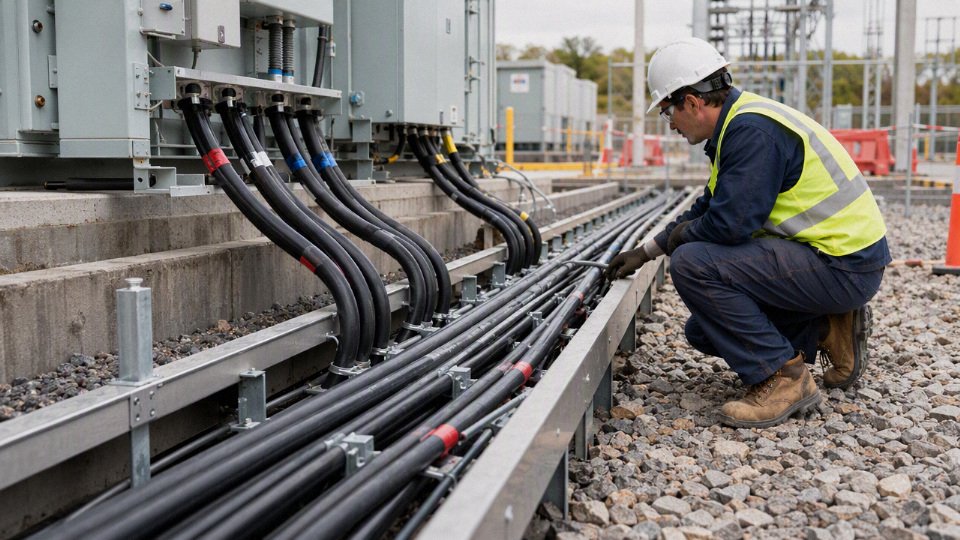
Conductor choice: copper, aluminum, and tinned copper
Copper is the conservative choice where compact size, high conductivity, frequent terminations, or tight equipment spaces matter. Motor control centers, VFD cabinets, panelboards, cranes, compact machinery skids, and retrofit work often favor copper because the conductor size is smaller for the same ampacity. That smaller diameter can save a surprising amount of grief when pulling through an old conduit run with two 90-degree bends and a junction box someone packed full twenty years ago.
Aluminum is attractive for feeders, long plant runs, utility-style connections, large service entrances, renewable energy balance-of-plant circuits, and installations where weight and material cost drive the job. The trade-off is size and termination discipline. Aluminum generally requires a larger conductor size for the same current, compatible lugs, correct oxide inhibitor practice where specified, controlled torque, and re-torque policy only where the equipment maker actually calls for it. Poor aluminum terminations are not an aluminum problem; they are usually a workmanship, lug, torque, or inspection problem.
Tinned copper sits in a different lane. It is chosen when corrosion resistance matters more than base material cost: marine equipment, coastal facilities, some chemical plants, wastewater sites, offshore packages, and damp areas where plain copper strands can darken and degrade over time. Tinning does not make a cable indestructible. The jacket, gland, sealing system, tray material, and drainage still decide whether the installation lasts.
The preferred conductor changes with the constraint. If the project is a compact OEM machine with limited terminal space, copper usually wins. If it is a 300 m outdoor feeder to a pump station and the route is open enough for larger cable, aluminum may be commercially better. If salt air or corrosive vapor is the daily atmosphere, tinned copper may be worth the premium even when the load current is modest.
Insulation and jacket selection for industrial 480 V service
XLPE and EPR are common insulation choices where thermal performance, dielectric strength, and industrial durability are needed. XLPE is widely used in power cables because it handles heat well and has good electrical properties. EPR is often favored where flexibility, moisture resistance, and rugged service are important, depending on the specific compound and standard. PVC appears in many low-voltage control and power cable designs, but its temperature rating, flexibility, flame behavior, and chemical resistance must be checked rather than assumed.
Jacket selection is where the plant environment starts to matter. A clean indoor electrical room is easy compared with a mill basement, mine, outdoor solar combiner route, or food plant washdown zone. Specify the jacket around the abuse it will actually see:
- Flame-retardant construction: needed where cables are routed in tray, tunnels, process buildings, or grouped installations subject to flame-spread requirements.
- Low-smoke zero-halogen compounds: useful in enclosed public, transport, data, offshore, or tunnel-type areas where smoke and acid gas are major hazards; they are not automatically required for every factory feeder.
- Oil resistance: important near hydraulic units, presses, rolling equipment, machining areas, diesel systems, and crane drives.
- UV resistance: necessary for rooftop conduit transitions, exposed tray, outdoor equipment skids, and renewable energy sites.
- Moisture resistance: relevant for duct banks, direct burial, washdown areas, basements, mines, and outdoor pull boxes that never stay as dry as the drawing suggests.
- Mechanical protection: armor, metal-clad construction, thicker jackets, conduit, tray covers, or guarded routing may be needed where forklifts, scrap, vibration, rodents, or falling tools are part of the environment.
The mechanism is simple but unforgiving: heat, moisture, chemicals, and mechanical damage age the insulation and jacket faster, which reduces dielectric margin and increases failure risk. Higher temperature accelerates insulation aging; oil can swell or soften the wrong jacket; UV can embrittle exposed material; water ingress can track along strands and into terminations. The best cable on the datasheet can fail early if the glands are loose, the tray has sharp burrs, or the cable sits in a flooded pull box all summer.
Voltage drop on long feeders and heavy motor loads
At 480 V, voltage drop can become a design driver before ampacity does. Long feeders to remote pumps, conveyors, cranes, mining systems, irrigation stations, renewable energy balance-of-plant circuits, and far-end production equipment may need larger conductors to keep voltage within equipment tolerance. Motors are especially sensitive during starting because inrush current can be several times running current, and the voltage sag appears right when the motor needs torque.
The path is direct: conductor resistance and reactance cause voltage loss as current rises. During motor starting, higher current creates a larger drop, reduced motor terminal voltage lowers starting torque, the motor accelerates more slowly, and the longer acceleration keeps current high for more time. That can trip protection, overheat the motor, upset a VFD DC bus, or make a crane feel weak at the far end of the runway.
Voltage drop analysis should be based on:
- Load current and starting current.
- Feeder length one-way, not just building distance.
- Conductor material and size.
- Power factor.
- Raceway or cable arrangement.
- Starting method: across-the-line, soft starter, VFD, reduced-voltage starter, or staged loading.
- Acceptable voltage at the equipment terminals.
- Utility or transformer regulation under load.
There is a trade-off. Oversizing conductors reduces voltage drop and losses, but it raises cable cost, drum weight, pulling force, termination size, and sometimes conduit or tray size. For a lightly loaded short feeder, buying larger cable “just in case” is wasted money. For a remote motor that starts under load, the larger conductor may be cheaper than nuisance trips, overheated windings, or a field retrofit after the plant is already running.
Fault current can control the cable decision
Steady-state ampacity is not always the limiting condition. On 480 V systems close to large transformers, switchgear, or generator sources, available fault current can be high enough that short-circuit withstand becomes a serious cable selection issue. The cable must survive thermally until the protective device clears the fault, and the grounding path must support enough fault current to operate the protection as intended.
This is where engineering and procurement need the same information. A conductor that carries 300 A in normal operation may not be acceptable if the protective device clearing time and available fault current exceed the cable’s short-circuit thermal capability. Cable construction can also matter for grounding conductors, armor bonding, concentric grounds, shields, and metallic sheath systems. The required checks come from the applicable code, protection study, cable manufacturer data, and equipment documentation; they should not be guessed from a catalog ampacity table.
Fault duty is one of the places where the answer stops being generic. The right cable depends on transformer size and impedance, source configuration, protective device type, trip settings, let-through energy, installation method, and the actual cable standard being applied.
Buying checklist for 480 V industrial cable
Use this before issuing a request for quotation or approving a substitute. It saves time for both sides and prevents the usual back-and-forth after the supplier has already priced the wrong construction.
- Confirmed nominal voltage
- 480Y/277 V, 480 V delta, 600Y/347 V, or another system.
- State whether the value is nominal, measured, or equipment nameplate voltage.
- System grounding
- Solidly grounded, resistance-grounded, ungrounded, corner-grounded delta, or separately derived.
- Include any ground-fault monitoring requirement.
- Phase count and conductor count
- Three phase, single phase, control pairs, grounding conductor, concentric neutral, or shielded construction.
- Do not assume “three phase” always means three conductors only.
- Neutral requirement
- Needed for 277 V lighting, controls, unbalanced loads, or harmonic-producing loads.
- Confirm neutral size if non-linear loads are present.
- Equipment load current
- Full-load current, continuous load, motor starting current, VFD output use, duty cycle, and future spare capacity.
- Installation route
- Tray, conduit, duct bank, direct burial, aerial, festoon, reel, mining trailing, indoor, outdoor, wet, corrosive, or hazardous area.
- Applicable standards and certificates
- NEC, UL, CSA, IEC, EN, project specifications, marine approvals, mining approvals, CPR class, flame test requirement, or local authority requirements as applicable.
- Environmental exposure
- Ambient temperature, oil, chemicals, sunlight, washdown, moisture, abrasion, rodents, vibration, and mechanical impact.
- Drum length and logistics
- Required cut lengths, pulling direction, maximum drum size, site unloading limits, storage conditions, and cable marking.
- Testing documents
- Factory test report, routine electrical tests, dimensional checks, material certificates, compliance declarations, and any project-specific inspection hold points.
For bulk procurement, send the cable schedule, single-line diagram, installation notes, and any specification pages rather than only a voltage and amp rating. A good supplier can price more accurately, flag mismatches early, and avoid offering a standard stock cable where the project actually needs a different insulation, jacket, certificate, or drum plan.
Procurement and documentation risks
A purchase order should never say only “three-phase 408 V” unless the project has formally defined what that means. Use a standard system designation such as 480Y/277 V, 208Y/120 V, 400Y/230 V, 600Y/347 V, or another recognized project voltage, then specify the cable standard, voltage rating, conductor size, insulation, armor, sheath, and test documentation required.
The problem is not academic. I have seen more schedule damage from one bad voltage phrase on a requisition than from the cable itself: the buyer copies a site measurement, the vendor quotes against a nonstandard description, the consultant rejects the submittal, and the plant is still waiting while the shutdown window gets burned.
Before placing the order, these documents should tell the same voltage story:
- Single-line diagram: nominal system voltage, transformer secondary, grounding method, and distribution level.
- Equipment nameplate: motor, VFD, MCC, transformer, heater, UPS, or panel voltage and frequency.
- Transformer nameplate: primary and secondary voltage, vector/grouping if relevant, taps, kVA, impedance, and grounding arrangement.
- Utility service agreement: contracted service voltage and tolerance basis, not just what a handheld meter read on a bad Tuesday afternoon.
- Panel schedule: voltage, phase count, breaker poles, neutral availability, and connected load descriptions.
- Cable schedule: feeder ID, from-to locations, conductor size, number of cores, grounding conductor, insulation level, armor, sheath, and installation method.
- Load list: rated voltage of each load, starting method, duty, harmonics where drives or rectifiers are involved, and spare capacity assumptions.
- Local electrical code and project specification: permitted cable type, flame rating, certification mark, installation practice, test requirements, and inspection authority expectations.
The mechanism is simple: an ambiguous voltage description moves downstream into every commercial and technical document. A sales quotation may interpret “408 V three phase” as a 400 V-class IEC project, while the site engineer intended a 480 V North American distribution system that happened to be measured low under load. The cable insulation might still be adequate in many cases, but the connected equipment, certification package, markings, and inspection basis may not be. That is where the expensive argument starts.
International projects make this worse. A skid builder may source motors and control panels from one country, the EPC contractor may issue drawings using another convention, and the final plant may be inspected under a third code environment. A “400 V” machine package installed on a “480 V” plant distribution system is not a paperwork difference; motors, drives, contactor coils, power supplies, surge protection devices, and heater banks may have different acceptable input ranges. Some equipment is dual-rated or has configurable taps. Some is not. Procurement must verify the nameplate and manual, not assume the voltage family is close enough.
For cable purchases, the certificate trail matters as much as the drum label. Cable certificates, factory test reports, datasheets, and sheath markings should align with the required standard or project specification, such as IEC, UL, CSA, BS, VDE, or a client-specific standard. A technically suitable cable can still be rejected if the marking, test report format, or certification basis does not match the contract. That sounds bureaucratic until a container is sitting at port or an inspector refuses energization because the supplied documentation does not match the approved submittal.
A useful requisition package usually states:
| Procurement item | What to specify clearly | Why it matters |
|---|---|---|
| Nominal system voltage | Example: 480Y/277 V, 3-phase, 4-wire, grounded wye | Prevents confusion between line-to-line and line-to-neutral values |
| Cable voltage class | As required by project standard and installation condition | Ensures insulation system and testing basis match the application |
| Applicable standard | IEC, UL, CSA, BS, VDE, or project specification | Drives construction, marking, testing, and acceptance documentation |
| Installation environment | Tray, conduit, direct burial, duct bank, offshore, high ambient, chemical exposure | Affects sheath, armor, flame rating, ampacity, and mechanical protection |
| Documentation package | Datasheet, certificate, factory test report, packing list, marking sample if needed | Reduces submittal rejection and inspection delay |
| Destination requirements | Country, port, language requirements if specified, packing constraints | Avoids customs, labeling, and handling problems |
The trade-off is speed versus control. A short purchase description may get a quote back faster, especially for common building wire or replacement cable, but it pushes interpretation risk onto the supplier and the buyer. A controlled requisition takes longer to prepare, yet it gives the manufacturer a defensible basis for construction, testing, labeling, and packing. The preferred approach flips only for a true like-for-like emergency replacement where the existing cable marking, approved drawing, and site voltage are confirmed and the plant accepts the documentation risk.
The practical consequences of getting this wrong are familiar:
- Rejected technical submittals because the quoted cable standard does not match the specification.
- Customs or inspection delays when markings and certificates do not align with the declared standard.
- Motors or drives supplied for the wrong voltage class.
- Emergency replacement purchases at premium freight cost.
- Warranty disputes after equipment is energized outside its rated condition.
- Commissioning failures caused by mismatched transformer taps, control power, or protection settings.
- Spare cable inventory that cannot be used on the intended project.
For industrial cable projects, Jinda’s useful role is not to guess what “408 V” means. It is to review the stated application requirements, align the cable structure with the required voltage class and standard, support technical documentation, manufacture in bulk, prepare export packaging, and support long-term supply where the project needs repeatable cable construction across multiple shipments. That works best when the buyer provides the single-line diagram, cable schedule, applicable standard, installation environment, and any required certificate format before the order is released.
Frequently asked questions
Is three-phase power 408 V or 480 V?
In North American industrial plants, three-phase power is commonly 480 V nominal, not 408 V. A meter may show a value below 480 V because of service variation, transformer loading, long feeder voltage drop, measurement location, or a fault condition.
If someone says “408 three-phase,” ask whether they mean:
- A measured line-to-line voltage at the equipment
- A mistaken reading of 480 V documentation
- A non-North American system being compared incorrectly
- A transformer or drive output under a specific load condition
Is 408 V a standard three-phase voltage?
No, 408 V is not normally used as a standard three-phase service designation in North American industrial distribution. Common systems are 208Y/120 V, 240 V delta, 480Y/277 V, and 600Y/347 V.
408 V is a normal nameplate designation for North American three-phase service.False
Common North American low-voltage utilization systems include 208Y/120 V, 240 V delta, 480Y/277 V, and 600Y/347 V. A 408 V reading is usually treated as a measured voltage, documentation error, transformer output issue, or diagnostic symptom rather than the nominal system name.
A true 408 V reading on a system expected to be 480 V is roughly 15% low. That is outside the usual plus or minus 5% Range A reference often associated with ANSI C84.1 for many low-voltage systems, so it deserves investigation rather than casual acceptance.
What does 480Y/277 V mean?
480Y/277 V means a three-phase wye system with 480 V measured line-to-line and 277 V measured line-to-neutral. The “Y” tells you the transformer or source is wye-connected and has a neutral point available.
The math is simple: in a balanced wye system, line-to-line voltage equals line-to-neutral voltage multiplied by 1.732. So:
- 277 V × 1.732 ≈ 480 V
- 120 V × 1.732 ≈ 208 V
- 347 V × 1.732 ≈ 600 V
In the field, 480Y/277 V often supplies 480 V motors and 277 V lighting from the same service, though the actual allowable use depends on the panel, grounding method, overcurrent protection, and local code.
Why do I measure less than 480 V?
A 480 V system is named by nominal voltage, not by the exact number your meter shows every minute. Utility tolerance, transformer tap settings, plant loading, feeder length, conductor size, poor terminations, and motor starting current can all pull the measured value down.
The location of the measurement matters. A main switchboard reading of 474 V and a far-end motor control center reading of 456 V under load tell a different story than 408 V at the service entrance. In practice, I would check:
- Line-to-line voltage at the service or main distribution board
- Line-to-line voltage at the load while operating
- Phase balance between all three phases
- Line-to-ground readings, if the system grounding method allows meaningful interpretation
- Transformer tap position and load current
- Loose lugs, overheated terminations, damaged cable, or undersized feeders
One low reading on a handheld meter is not a diagnosis. A stable 408 V reading on a supposed 480 V system is not something I would ignore.
Can a 480 V motor run on 408 V?
Usually, no — not reliably or safely unless the motor, drive, and application have been specifically engineered for that condition. A 408 V supply is about 15% below 480 V, and that can increase current, reduce torque, overheat windings, trip overloads, or make the motor fail to accelerate under load.
Induction motor torque is strongly affected by voltage; as voltage drops, available torque drops sharply. A lightly loaded fan might spin and appear “fine” for a while, but a loaded conveyor, pump, compressor, or crusher may stall, pull high current, and cook the motor. VFD-fed motors are a separate case, but the drive input range, output voltage, torque requirement, and derating all have to be checked against the manufacturer’s data.
Is 400 V the same as 480 V?
No. 400 V three-phase is common in many IEC-based systems, typically associated with 400/230 V distribution. It is not the same system as 480Y/277 V.
Some equipment is dual-rated or designed with broad input ranges, especially power supplies, VFDs, and certain international machines. Motors, heaters, transformers, contactor coils, lighting, and control circuits are less forgiving. Before connecting 400 V equipment to 480 V, or 480 V equipment to 400 V, check the nameplate, wiring diagram, insulation rating, frequency, control voltage, and manufacturer documentation.
What cable voltage rating is used for 480 V systems?
For 480 V industrial systems, cable is commonly selected with a voltage rating above the nominal system voltage, often 600 V class in North American practice or 0.6/1 kV in many IEC-style project specifications. The correct choice depends on the installation standard, insulation type, grounding system, environment, and project specification.
Do not buy cable described only as “480 V cable.” Cable procurement should state the actual recognized rating and construction, such as conductor material, insulation type, sheath or jacket, armor if required, temperature rating, flame performance, and applicable standard.
Should cable be ordered by measured voltage or nominal voltage?
Order cable by the nominal system voltage and the project specification, not by a temporary measured voltage. If the plant is designed as 480Y/277 V, the cable package should be specified for that system even if one panel happens to measure 468 V during operation.
Measured voltage is still useful, but for troubleshooting and voltage-drop verification. Procurement should not downgrade cable rating because someone saw 408 V on a meter. That is how plants end up with mismatched documentation, rejected inspections, or equipment that cannot be reused when the voltage issue is corrected.
How do I know if my system is wye or delta?
Start with the source documentation, not guesswork. The transformer nameplate, service drawings, switchgear labels, and grounding diagram should identify whether the system is wye, delta, corner-grounded delta, or another arrangement.
Field clues can help:
- 480Y/277 V wye usually has about 480 V line-to-line and about 277 V line-to-neutral.
- A delta system may have line-to-line voltage available without a neutral.
- A grounded conductor or high-leg arrangement can create readings that surprise people who only check phase-to-ground.
- A missing or poorly identified neutral is a documentation and safety problem, not just a labeling nuisance.
Use a properly rated meter and safe test procedure. Opening a live 480 V cabinet to “just check” is not a job for an unqualified person.
Who should verify a 408 V reading on site?
A qualified electrician, electrical engineer, or service technician should verify it using properly rated instruments and safe work practices. If the reading is at the utility service point, the utility or service provider may also need to be involved.
The verifier should confirm:
- Meter category rating and calibration status
- Measurement points and whether readings are line-to-line or line-to-neutral
- Voltage on all three phase pairs
- Load condition during the test
- Transformer tap settings
- Feeder voltage drop
- Evidence of overheated terminals, loose connections, or damaged cable
- Whether the one-line diagram matches the actual installation
For procurement teams, the safest practical move is to hold cable or equipment orders until the nominal system voltage is confirmed in writing. A 480 V project and a 400 V project can look similar on a quotation sheet, but they are not the same electrical package.
Verify before ordering cable
For a standard North American industrial three-phase project, assume 480 V nominal is more likely than 408 V nominal, but do not buy cable on that assumption alone. The correct procurement answer comes from the service drawings, transformer and equipment nameplates, system configuration, and qualified voltage measurements taken under known load conditions.
A 408 V meter reading on a circuit believed to be 480 V is not a cable-sizing detail to “round off.” It is a warning flag. It may come from measuring the wrong points, reading during abnormal voltage drop, looking at a nonstandard or misapplied transformer tap, or misunderstanding a wye relationship. Any of those can put the buyer in the same bad place: cable ordered correctly for the paperwork, but wrong for the plant.
Use a short verification sequence before releasing the purchase order:
- Confirm the nominal service voltage
- Check the utility service documents, one-line diagram, transformer schedule, MCC schedule, and panel nameplate.
- Look for explicit system language such as:
- 480Y/277 V
- 480 V delta
- 208Y/120 V
- 240 V delta
- 600Y/347 V
- Do not treat a handwritten “3 phase” note as a voltage specification.
- Identify whether the system is wye or delta
- A 480Y/277 V system has a neutral reference and should show roughly 277 V from line to neutral under normal conditions.
- A 480 V delta system may not have a usable neutral in the same way, and phase-to-ground readings can be misleading depending on grounding method.
- Corner-grounded, resistance-grounded, and ungrounded systems need extra care because casual meter readings can tell an incomplete story.
- Record both line-to-line and line-to-neutral readings
- Measure L1-L2, L2-L3, and L3-L1.
- If a neutral is present and intentionally connected, measure L1-N, L2-N, and L3-N.
- Record where the reading was taken: service entrance, transformer secondary, MCC bus, local disconnect, or machine terminals.
- Check load conditions during measurement
- A lightly loaded system and a heavily loaded system can read differently.
- Long feeder runs, undersized conductors, weak transformer capacity, poor terminations, and overloaded distribution can pull voltage down at the machine end.
- In practice, I want to know whether the reading was taken with the compressors, chillers, welders, or large drives actually running, not just with the disconnect open.
- Review equipment nameplates
- Motors, VFDs, heaters, compressors, control transformers, and imported machines may have different acceptable voltage ranges.
- A machine marked 380/400/415 V is not the same purchasing case as one marked 460 V or 480 V.
- Cable voltage rating, insulation system, ampacity, and conductor count must match the installed system, not a guessed regional convention.
- Confirm the applicable cable standard
- North American projects may reference UL, CSA, NEC-related requirements, or project-specific specifications.
- Export projects may call for IEC-based constructions or special fire-performance requirements.
- Flame rating, smoke performance, temperature class, armoring, shielding, oil resistance, UV exposure, tray approval, and installation method can change the cable design even when the nominal voltage stays the same.
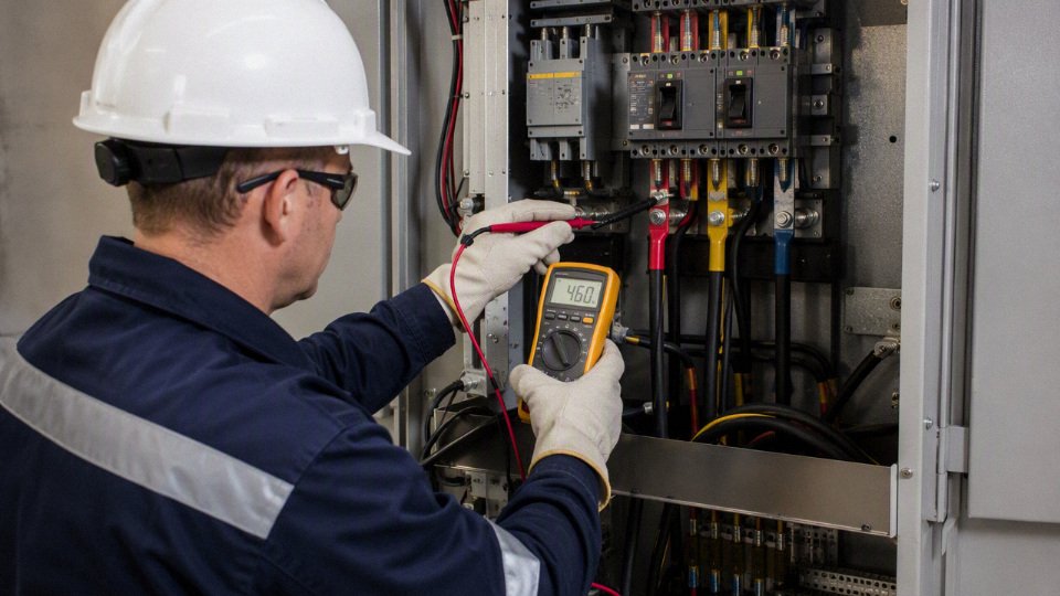
A steady 408 V reading on a supposed 480 V system should trigger engineering investigation before procurement, not a quick order for “408 V cable.” The mechanism is simple: voltage affects insulation selection, equipment compatibility, motor torque, drive behavior, current draw, and voltage-drop margin. If the system is actually low because of supply or distribution problems, buying cable around the symptom does not fix the root cause. If the system is actually a different nominal voltage, then the one-line diagram, equipment list, and cable schedule all need to agree before money is committed.
For purchasing, prepare the cable request as an engineering package rather than a voltage phrase. Send the manufacturer:
- Nominal voltage and maximum system voltage, if specified
- Load current, demand assumptions, and any starting or overload conditions
- Conductor count, conductor material, and required conductor size if already engineered
- Grounding method and grounding conductor requirements
- Wye or delta configuration
- Installation environment: tray, conduit, direct burial, tunnel, outdoor exposure, marine, mining, chemical area, or high-temperature zone
- Approximate route length and allowable voltage drop target
- Required standard or code reference
- Flame, smoke, halogen, oil, sunlight, abrasion, or chemical-resistance requirements
- Temperature rating and ambient temperature assumptions
- Shielding, armor, jacket color, marking, packing, and drum requirements
- Required certificates, test reports, inspection documents, or third-party approvals
- Project schedule, delivery batch plan, and any spare length policy
The trade-off is speed versus certainty. A fast purchase based on “three-phase 480” may work for a routine replacement where the plant drawings, nameplates, and previous cable records all agree. That shortcut stops being sensible when the measured voltage is 408 V, the machine is imported, the neutral arrangement is unclear, or the project involves bulk cable procurement across several feeders.
Send project drawings, cable schedules, load data, measured voltage records, and required standards to Jinda for technical review. Jinda can review the application, recommend suitable cable construction, prepare a quotation, and plan production around the confirmed voltage requirements and project schedule.