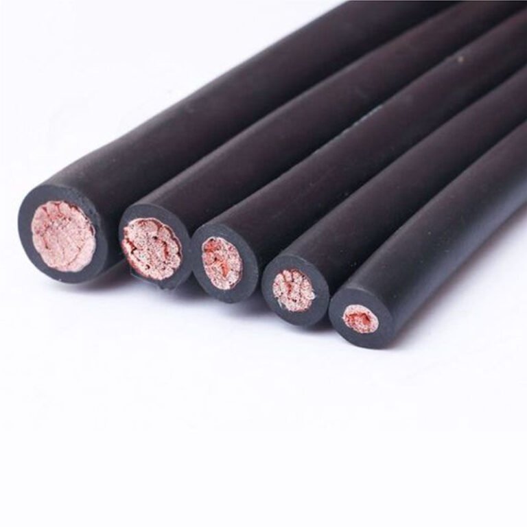
Wrong cable choice in an industrial plant doesn’t announce itself — it creeps up through nuisance trips, insulation failures at 3 a.m., and scrap batches nobody can explain until someone finally traces the fault back to a standard building wire that was never rated for the heat cycling near a press or the chemical wash-down in a food processing aisle. The maintenance cost alone can run into tens of thousands before anyone pulls the cable schedule and asks the right question. Fix it upstream, at the specification and procurement stage, and most of that pain simply doesn’t happen.
Industrial environments demand wiring specifically rated for their actual stresses: operating temperatures from 70°C (standard PVC) up to 180°C or beyond (silicone rubber), mechanical protection against crush and flex, IP ratings of at least IP54 on a general plant floor and IP65 or higher in wash-down or wet zones, and chemical resistance matched to the specific process fluids present. No single cable type covers every situation — the right choice depends on temperature, movement, exposure, and regulatory requirements.
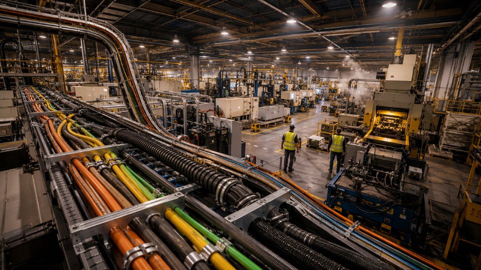
What makes this genuinely complicated is that a plant floor is rarely one environment. Within fifty meters you might have a dry machining bay, a coolant-flooded cutting zone, a cable tray running directly above a heat treat furnace, and a flexible drop to a robot arm cycling ten thousand times a month. Each one of those locations has a different failure mode waiting for the wrong cable. The sections below work through how to match wiring type to those real conditions — and where the shortcuts tend to break down.
Conductor Materials and Cross-Section Sizing for Industrial Power Loads
Choosing the wrong conductor material or undersizing a cross-section in an industrial plant doesn’t just trip a breaker — it starts a chain: overheated terminations, insulation breakdown, motor trips, unplanned downtime, and in the worst cases, a cable fire that shuts a line for days. Getting this right is foundational work, and it’s worth slowing down on.
Copper vs. Aluminum — the Practical Tradeoffs
Copper’s conductivity runs around 58 MS/m against aluminum’s roughly 35 MS/m. That gap means an aluminum conductor needs a cross-section approximately 1.6 times larger to carry the same current as copper — which matters in crowded cable trays and tight panel knockouts. But the conductivity difference isn’t even the main reason copper dominates industrial control and power wiring. It’s termination reliability.
Aluminum oxidizes quickly at exposed surfaces. That oxide layer is resistive, and under load cycling it generates heat, which accelerates further oxidation, which increases resistance further. In a motor control center with dozens of terminations getting torqued once during installation and rarely checked again, this becomes a serious failure mode. Copper handles vibration fatigue much better too — on machine frames with continuous vibration, aluminum strands can cold-crack at termination lugs within a few years.
Aluminum does make sense for large fixed-installation feeder cables, typically above 95 mm², where the weight and cost savings become real. A 240 mm² aluminum feeder running 50 meters from a substation to a main distribution board is a legitimate engineering choice. When you go that route, anti-oxidant compound at every termination is not optional — it’s the difference between a joint that lasts 20 years and one that fails in three. Use a jointing compound rated for the conductor material and torque to the lug manufacturer’s specification, not to feel.
Stranded Construction and IEC 60228 Conductor Classes
Solid conductors have no business in most industrial wiring. For fixed installations, Class 2 stranded is the standard — it handles the bending stress of installation routing through conduit and tray without work-hardening the way solid wire does, and it’s what IEC 60228 defines for fixed power wiring. Class 5 fine-wire stranded is for flexible connections: motor leads, control panel whips, anything that gets repositioned during maintenance. Class 6 goes further — the extremely fine strands in Class 6 cables are designed for continuous flexing in drag chains and robotic servo applications, where a Class 2 cable would fatigue and break conductors within months.
Misapply these and the consequences are predictable. A Class 2 cable routed through a cable carrier on a moving gantry will show conductor fractures within 6–18 months depending on flex cycle frequency and bend radius. By that point the damage is usually invisible from outside — resistance rises gradually until the circuit drops under load.
Cross-Section Sizing Under Continuous Industrial Load
| Circuit Type | Typical Cross-Section | Current Range | Key Derating Consideration |
|---|---|---|---|
| Control circuits (PLC I/O, instrumentation) | 1.5 mm² | Up to 10 A | Group derating if >6 cables bundled |
| Branch circuits, lighting, small loads | 2.5 mm² | Up to 16 A | Ambient above 30°C: apply 0.94 factor |
| Small motor feeders (0.75–2.2 kW) | 4–6 mm² | 16–25 A | Continuous duty: apply 0.8–0.85 utilization factor |
| Mid-range motor feeders (4–15 kW) | 10–16 mm² | 32–63 A | Check voltage drop over long runs |
| Main distribution boards | 16–50 mm² | 80–200 A | Grouping and enclosure temperature critical |
The utilization factor is where plant electrical designs routinely go wrong. Motors in continuous-duty processes — conveyors, compressors, mixers — often run at 80–100% of rated load for full shifts. Sizing cable to the motor’s rated current is not conservative enough; design current should be calculated at the actual expected load, then a 0.8–0.85 utilization factor applied before comparing to the cable’s rated ampacity. Skip this step and you’re running cable at the edge of its thermal limit for hours at a time. Insulation degrades faster, terminations run hot, and the cable that was supposed to last 25 years starts causing problems at year eight.
Derating for cable grouping is equally underestimated. Twelve cables laid flat and touching in a tray — a completely normal industrial arrangement — can derate individual cable ampacity by 40–50% compared to a single cable in free air. The specific factor depends on how many cables are grouped, whether the tray is ventilated, and the ambient temperature in that section of the plant. Near furnaces or in poorly ventilated mezzanines, ambient temperatures above 40–45°C are common, and that alone shifts the derating curve meaningfully.
Class 5 fine-wire stranded copper cable is required for flexible connections to motors under IEC 60228True
IEC 60228 Class 5 defines fine-wire stranded conductors intended for flexible applications, and this is the appropriate construction for motor leads and control panel flexible connections that are repositioned during maintenance or commissioning.
One practical note: when specifying cables for drag-chain or continuous-flex applications, confirm the cable is explicitly rated for that service by the manufacturer — not just that it uses Class 6 conductors. The jacket compound, lay length, and core arrangement all affect flex life. A cable built with Class 6 conductors but a rigid jacket will still fail early in a drag chain.
Insulation and Jacket Compounds: Matching Chemistry to the Hazard
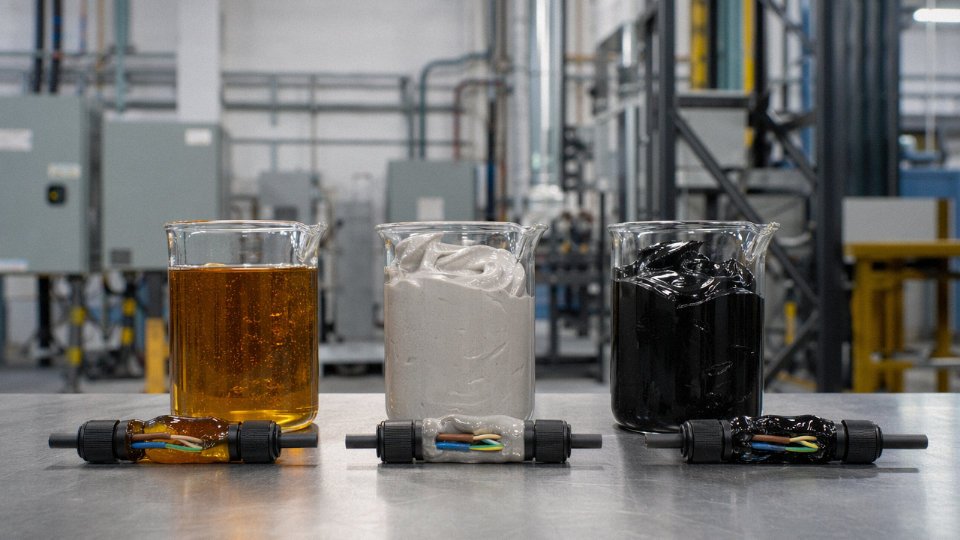
Defaulting to PVC because it’s cheap is one of the most common — and expensive — mistakes in industrial cable procurement. The insulation and jacket compounds determine how a cable behaves under heat, cold, moisture, UV, mechanical stress, and fire. Get the chemistry wrong and you’re not just looking at premature failure; you’re looking at a fire investigation, a production shutdown, or a warranty dispute with your cable supplier that goes nowhere because the spec sheet was never properly reviewed.
PVC: The Baseline, and Its Real Limits
Polyvinyl chloride is the workhorse of low-voltage wiring globally, and for good reason — it’s cost-effective, reasonably oil-resistant at light-duty exposure, and easy to process. Standard PVC insulation carries a 70°C conductor temperature rating, which is adequate for most dry, temperate, indoor plant environments running moderate current densities.
The problems start at the edges of that envelope. Below roughly -15°C, PVC plasticizers migrate and the compound becomes brittle — flex it in a cold store or an outdoor Norwegian substation in January and you’ll crack the insulation. On the other end, in a fire scenario, PVC releases hydrogen chloride gas (HCl). HCl is corrosive enough to destroy switchgear and control panels well beyond the actual fire zone, and it’s acutely toxic to anyone in the building. In a confined motor control room, that’s a serious consequence, not a theoretical one.
PVC insulation emits hydrogen chloride gas when burned, which can damage electrical equipment in adjacent areas even if those areas are not directly affected by the fire.True
PVC contains chlorine by composition; combustion produces HCl gas, which is corrosive to metals and electronics and has been the cause of secondary equipment losses in industrial fire events.
XLPE and EPR: The Engineering-Grade Choices
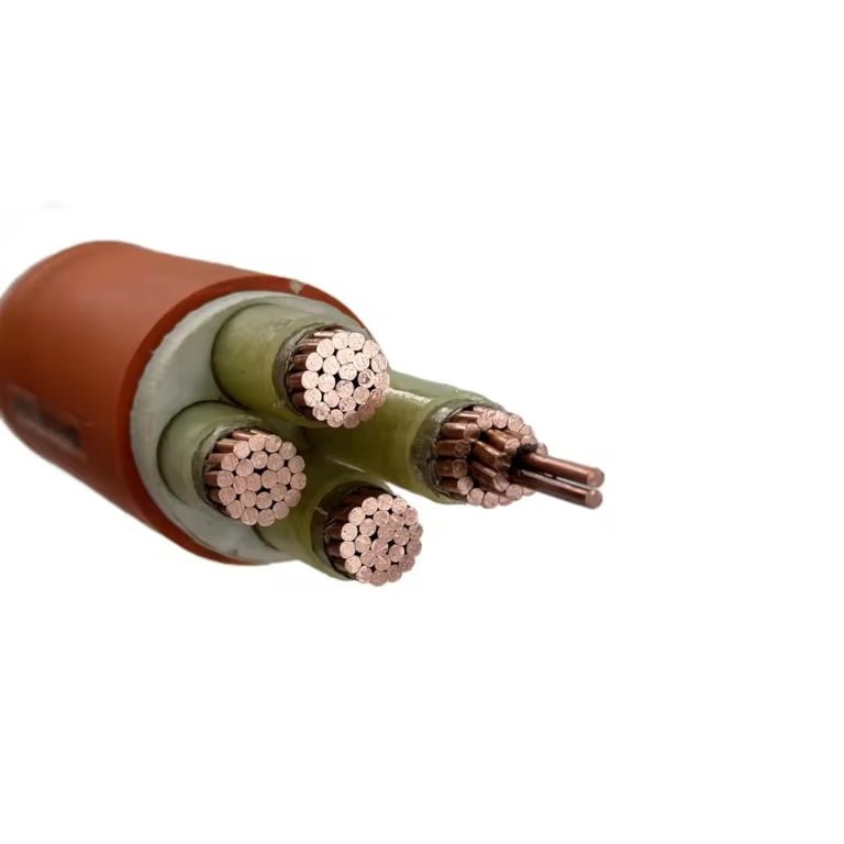
Cross-linked polyethylene is thermosetting — the cross-linking process means the polymer structure won’t soften and deform under sustained heat the way PVC does. XLPE holds to 90°C continuous and can handle upward of 250°C during a short-circuit event without the insulation collapsing onto the conductor. Its moisture resistance is excellent, dielectric losses are low, and for medium-voltage feeders — 6 kV, 10 kV, 33 kV — it’s essentially the standard choice in most industrial plants globally. Underground distribution loops inside a plant site are another natural application, where soil moisture and long-term thermal cycling rule out anything softer.
Ethylene propylene rubber fills a different niche. EPR stays flexible to around -40°C, which makes it the material of choice for outdoor crane trailing cables, mining applications, and shipboard wiring where the cable is being bent repeatedly in cold conditions. Its ozone and UV resistance is significantly better than XLPE, so for exposed outdoor cable runs in a port facility or a quarry, EPR will outlast XLPE by years.
Silicone and LSZH: Specialist Territory
Silicone rubber is rated to 180–200°C continuous, sometimes higher in specialty compounds. It belongs near furnaces, on baking oven conveyor systems, and in steel plant environments where radiant heat from molten metal or kilns is unavoidable. The cost is considerably higher than XLPE — roughly 3x to 5x depending on conductor cross-section and market conditions — so it should only be specified where thermal extremes genuinely require it, not as a general “safe choice.”
LSZH (low-smoke zero-halogen) compounds are mandatory — not optional — in offshore platforms, tunnels, and public infrastructure projects under EN 50575 and IEC 60332-3. The fire performance classification system matters here: Class Fca or B2ca ratings under EN 50575 set specific limits on smoke opacity, HCl emission, and flame propagation. When reviewing factory test certificates for LSZH cable, ask specifically for the EN 50575 declaration of performance, not just a generic “halogen-free” claim on the datasheet.
Jacket Selection for Chemical Exposure
The outer jacket is a separate material decision from the insulation, and it’s frequently underspecified in procurement.
| Environment | Recommended Jacket | Why |
|---|---|---|
| Hydraulic oil, cutting fluids (automotive plant) | Nitrile rubber (NBR) | Resistant to petroleum-based oils and fuels |
| Bleach, acid wash-down (food processing) | Chlorinated polyethylene (CPE) | Resists oxidizing chemicals, maintains flexibility |
| Drag-chain, robotic cable tracks | Polyurethane (PUR) | High abrasion resistance, survives 10,000+ flex cycles |
| Outdoor UV exposure | EPR or PVC with UV stabilizers | Ozone and UV degradation resistance |
Polyurethane in particular is worth understanding — in a drag-chain application cycling 50,000 times per year on an automotive assembly robot, a standard PVC-jacketed cable will fail in months. A PUR-jacketed cable specified for continuous flexing will last years. The upfront cost difference is real; the downtime cost of an unplanned cable failure mid-shift is usually larger.
Reading Compound Designations on Test Certificates
IEC and VDE cable designations encode the insulation and jacket chemistry directly. In a VDE designation like N2XY, the “2X” indicates XLPE insulation and “Y” indicates PVC outer sheath. LSZH compounds appear as “HM” or “2Y(ST)H” depending on the standard. Procurement teams verifying material specifications should cross-reference the cable’s designation against IEC 60502 (medium-voltage), IEC 60227 (PVC-insulated), or IEC 60245 (rubber-insulated) and request the corresponding factory test reports — not just the product catalog page. If the test certificate references a compound designation you can’t map to a recognized IEC or VDE code, that’s worth a conversation with the manufacturer before a large order is placed.
Armoring, Shielding, and Mechanical Protection Systems
Physical protection isn’t an afterthought in industrial wiring — it’s often what determines whether a cable survives five years or five months. The right combination of armor, shielding, and raceway depends on installation method, the mechanical hazards specific to that section of plant, and the electromagnetic environment the cable passes through. Getting this wrong shows up as ground faults from crushed insulation, nuisance trips on VFD drives from injected noise, or — worst case — a fire in a cable tray because a rodent chewed through an unarmored run in a food processing basement.
Steel Wire Armor and When to Choose Round vs. Flat
Galvanized steel wire armor (SWA) is the workhorse for direct-buried feeders, cable tray installations, and anywhere mechanical abuse is a real risk. The individual wires wrap helically around the cable core, giving it both crush resistance and a degree of longitudinal tensile strength — useful when cables are pulled through ducts or supported over long vertical drops. Crush load ratings typically fall in the 450–500 N/cm range or above, enough to handle most cable tray stacking scenarios and incidental forklift contact on properly routed buried runs.
The round wire vs. flat wire distinction matters more than most procurement specs acknowledge. Round wire armor handles bending better, making it the right call for multi-core cables that need some flexibility during installation in congested areas. Flat wire armor — also called flat steel wire armor (FSWA) — is specifically suited to single-core cables because its geometry provides equivalent mechanical protection without creating a closed magnetic loop. On a single-core AC cable carrying significant current, steel round wire armor would form exactly that loop, inducing eddy currents and hysteresis heating that can reduce ampacity noticeably and, in severe cases, overheat the cable jacket. Flat tape breaks the continuous magnetic circuit and sidesteps the problem.
Aluminum Wire Armor for Long Tray and Overhead Runs
Aluminum wire armor (AWA) solves two problems at once on large single-core AC circuits above roughly 70 mm²: it’s non-magnetic, so it eliminates the hysteresis heating issue entirely, and it’s substantially lighter than steel — typically 30–40% weight reduction depending on cable diameter. On long cable tray runs spanning 50 m or more, that weight difference translates into real installed cost savings in support structure and labor. AWA is also the standard choice for overhead distribution runs where dead-load matters. The trade-off is that aluminum armor is softer, so in environments with aggressive rodent activity or high impact risk, SWA still wins on pure mechanical robustness.
Steel Tape Armor for Fixed Underground and Duct Work
Steel tape armor (STA) uses corrugated or smooth steel tape applied longitudinally or helically rather than individual wires. It handles longitudinal crush well and keeps the cable profile compact — useful when pulling through ducts where tight bend radii aren’t a concern and the cable stays fixed once installed. It’s less flexible than SWA, so field bending during installation requires more care. In practice, STA suits medium-voltage feeder cables in underground duct banks or direct-buried HV installations better than flexible process connections.
EMI and RFI Shielding: Matching Shield Architecture to the Noise Environment
Shielding selection depends almost entirely on the frequency range of the interference and the sensitivity of the signal being carried. These are genuinely different problems.
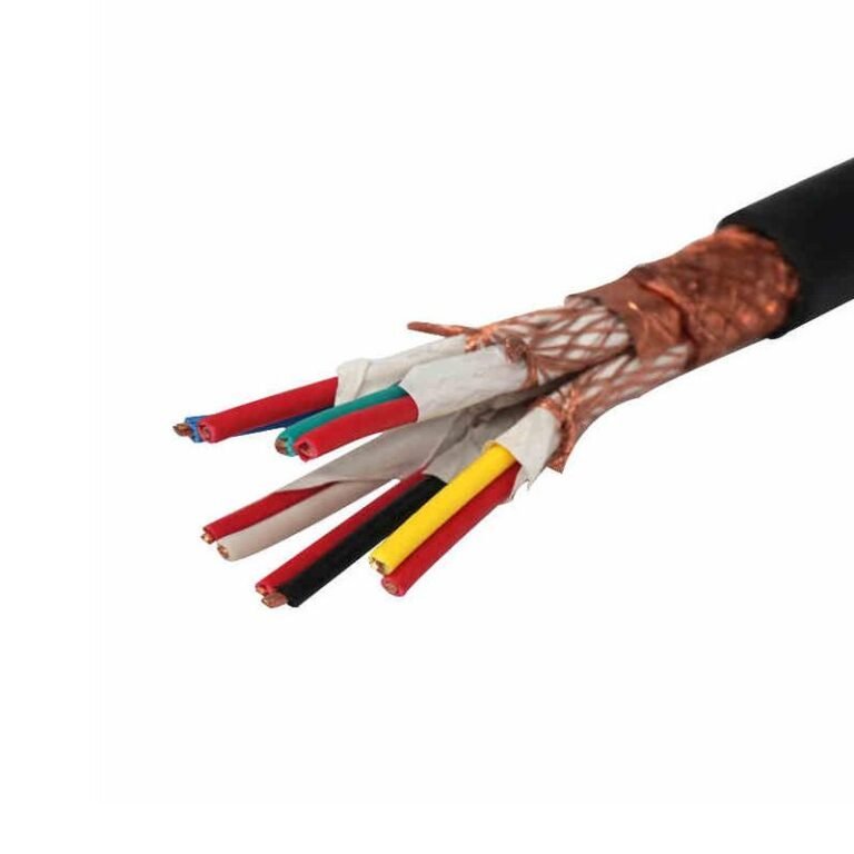
For instrumentation cables — 4–20 mA loops, thermocouples, RTD circuits — an overall aluminum-foil/polyester tape shield with a drain wire is usually sufficient. These circuits are vulnerable to low-frequency inductive pickup from nearby power cables, and foil shields with a solid ground reference handle that effectively. The drain wire is critical; a foil shield floating at one end provides almost no protection in practice.
Servo drives and VFD signal cables are a different story. Those circuits deal with broadband high-frequency noise from PWM switching, typically in the range of tens to hundreds of kilohertz. Braided copper shields at 85–95% coverage provide meaningful high-frequency suppression that foil alone cannot match. The coverage percentage matters — an 85% braid still passes some noise; 95% coverage is worth specifying when the drive manufacturer’s commissioning notes flag EMI sensitivity.
Multi-conductor instrumentation cables running in the same tray as high-current power feeders present the hardest case. Here, individually shielded pairs — each pair with its own foil and drain — are the correct architecture. An overall shield on a multi-pair cable does nothing to prevent crosstalk between pairs inside the cable itself.
A cable with only an overall foil shield provides adequate EMI protection for servo drive signal cables in high-frequency noise environments.False
Foil/polyester tape shields are effective for low-frequency noise rejection in standard instrumentation circuits, but servo and VFD signal cables require braided copper shields at 85–95% coverage to suppress broadband high-frequency interference from PWM switching. An overall foil shield alone is insufficient for this application.
Conduit Systems: Complement, Not Default
Rigid galvanized steel conduit makes sense in areas where the wiring genuinely needs to be field-replaceable — control panels in machinery that gets retooled frequently, for instance — or where impact risk is severe enough that even armored cable needs secondary protection. It adds cost and installation time, and it’s overkill in most fixed-tray applications.
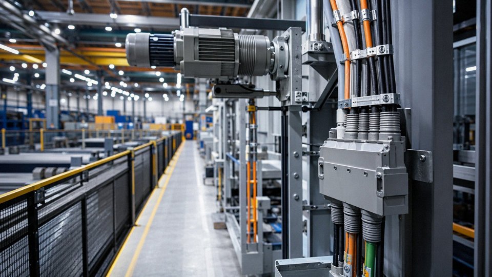
Liquid-tight flexible metal conduit (LFMC) is what you actually see on motor and pump final connections throughout well-run plants. It accommodates vibration, allows easy realignment during motor changeouts, and seals against coolant and wash-down splash. The flex cycle rating matters: cheaper grades are rated for around 10,000 cycles, while industrial-grade LFMC runs to 50,000 or more — a meaningful difference on a motor that vibrates continuously.
PVC conduit is fine for dry secondary areas with low mechanical risk: lighting circuits in a clean utility room, for example. It has no place near heavy equipment, in areas subject to thermal cycling, or anywhere a forklift might pass.
Cable Tray Fill and Segregation
Ladder tray is standard for large power cables, and the 40% fill rule by cross-sectional area isn’t arbitrary — exceeding it creates heat buildup that requires ampacity derating, which means either upsizing conductors or accepting reduced current capacity. Perforated tray suits mixed power and control runs. Solid-bottom tray is the right choice for instrument cables where you want a degree of electrostatic isolation from power runs in adjacent trays, and where you’re routing in dusty environments that would clog a ladder tray rapidly.
Segregation between power and instrument cables deserves more attention than it usually gets on plant layouts. Running a 4–20 mA loop cable 50 mm away from a 400 V feeder in the same ladder tray is asking for noise problems regardless of how good the shielding is.
Jinda manufactures SWA, AWA, and LSZH-jacketed armored cables built to IEC 60502, IEC 60227, and BS 5467, with third-party test certificates available to support international project specifications. For procurement teams sourcing against a specific project spec, requesting the actual test certificates — not just a declaration of conformity — is standard practice on any serious industrial or infrastructure project.
Voltage Class Selection: Low Voltage, Medium Voltage, and Instrumentation Cables
Understanding cable voltage ratings trips up even experienced procurement teams, mostly because the notation isn’t intuitive until you’ve worked with it a few times. The standard format is U0/U — conductor-to-earth voltage over conductor-to-conductor voltage — so a 0.6/1 kV cable means 600 V phase-to-earth and 1,000 V phase-to-phase. That single designation covers the entire practical range of standard industrial low-voltage distribution: 400 V three-phase TN systems, 690 V motor feeders, and most inverter-fed drive outputs you’ll find on a typical plant floor.
Why 400 V Systems Need 0.6/1 kV Cable, Not “500 V Rated” Cable
This is where under-specification quietly creates liability. A 400 V three-phase system produces roughly 231 V phase-to-earth under normal conditions, so on paper a 500 V-rated cable looks adequate. It isn’t. The 0.6/1 kV class carries an impulse withstand rating of 8 kV (Uimp), which is what protects the insulation from transient overvoltages generated by switching operations, capacitor bank switching, and — increasingly common — VFD output switching edges. Those transients can hit 2–4 kV in poorly bonded installations. Using a lower-rated cable doesn’t fail immediately; it degrades the insulation incrementally through partial discharge until you get a fault, usually at the worst possible moment during a high-load production run.
A 0.6/1 kV rated cable is required for 400 V three-phase industrial systems because the voltage class covers fault-to-earth stress and the 8 kV impulse withstand rating, not just the nominal system voltage.True
IEC 60502-1 defines the 0.6/1 kV class with an 8 kV Uimp to handle switching transients. A 500 V-rated cable lacks this impulse withstand level and is not suitable for industrial LV distribution per IEC standards.
Medium-Voltage Construction: More Than Just Thicker Insulation
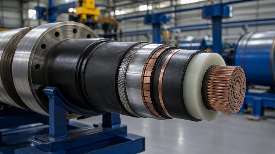
For plant distribution at 6 kV, 11 kV, or 33 kV — feeding large motors, internal substations, or campus-level ring mains — the cable construction becomes considerably more involved. A proper 6.35/11 kV XLPE cable has a conductor screen (semi-conductive layer that smooths the electric field at the conductor surface), then the XLPE insulation body, then an insulation screen, then a copper wire screen, bedding, armor, and outer sheath. Every layer has a specific function. The conductor and insulation screens exist purely to control field stress geometry and suppress partial discharge at those voltage gradients — omit either screen and you get concentrated field stress at any surface irregularity, which initiates PD and eventually tracked failure. Medium-voltage cable joints and terminations are particularly unforgiving here; in my experience, more MV cable failures trace back to poorly executed terminations than to the cable itself.
Instrumentation and Control Cables: Small Conductors, Precise Noise Architecture
Instrumentation cables rated 300/500 V are typically 0.5–1.5 mm², which looks almost fragile next to power cables, but their engineering is in the signal integrity, not the ampacity. Twisted pairs reduce loop inductance and improve common-mode noise rejection — critical for 4–20 mA loops running near variable-speed drives or high-current bus bars. Individual pair screening handles localized interference; overall screening handles plant-wide noise floors. Both together is standard for anything near a VFD panel. Skimping and using unscreened cable to save cost in a new installation is a reliable way to spend three weeks chasing ghost faults in a process control loop later.
Industrial Communication Cables: Specification Matters More Than It Should
PROFIBUS cable has a defined 120 Ω characteristic impedance and the violet sheath is a convention, not decoration — it helps maintenance crews identify the bus quickly during fault-finding. PROFINET uses CAT 6A industrial Ethernet with IP67-rated connectors for anything outside a cabinet. Standard commercial IT patch cable has no business in either application. Impedance mismatch on PROFIBUS at longer runs causes reflection and communication errors that look intermittent and are genuinely difficult to diagnose. Commercial Ethernet jackets are too soft for industrial flex and abrasion duty, and the screening is inadequate for EMI environments near drives and contactors. DeviceNet similarly specifies cable impedance and color coding; use it.
VFD Output Cables: The High dV/dt Problem
Variable frequency drives generate output pulses with rise times that can reach up to 10 kV/µs depending on the switching frequency and IGBT characteristics. Standard 0.6/1 kV cable can handle this short-term, but over months of continuous operation the insulation stress accumulates. Dedicated VFD cable uses reinforced insulation and — critically — a symmetrical three-conductor-plus-ground layout with the ground conductors distributed around the phase conductors rather than grouped to one side. That geometry reduces common-mode current and the associated bearing currents that destroy motor bearings over 12–24 months of VFD operation.
Cable length matters too. Reflected wave overvoltage at the motor terminals increases with cable length and carrier frequency; the practical limit before you need output reactors or dV/dt filters sits somewhere in the 30–100 m range depending on drive brand, carrier frequency setting, and motor terminal insulation class. Check the drive manufacturer’s cable length table — not as a formality but because exceeding it with a long run to a remote pump or fan regularly produces premature motor winding failures that no one initially connects to the cable installation.
Installation Methods That Determine Long-Term Wiring Reliability
Even a perfectly specified cable — right conductor cross-section, correct insulation compound, appropriate voltage class — will fail prematurely if the installation is sloppy. In my experience, termination failures and bend-radius violations account for a disproportionate share of industrial cable faults, far more than outright material defects. Specification gets the attention; installation gets ignored until something trips a breaker or catches fire.
Bending Radius: The Rule Installers Most Often Break
Power cables in fixed installations require a minimum bending radius of 12–15× the overall cable diameter. Flexible cables — those routed to moving machinery or used in festoon systems — need 20× or more, depending on the manufacturer’s data sheet. Violate that and you’re crushing conductors against the armor or cracking insulation at the bend point, damage that’s invisible until the cable fails under load months later.
The worst place this happens is at motor terminal boxes. An installer is trying to get a 35 mm² armored cable into a small gland entry at an awkward angle, and the cable gets forced into a tight reverse bend right where it enters the box. Warranty void, insulation compromised, and the motor trips on a ground fault six months into production. Use a 90° gland entry adapter or re-route the final drop — it takes twenty minutes and saves a shutdown.
Cable Support Spacing and Tray Management
Heavy armored power cables on horizontal cable trays need support every 1.5–2 m, depending on cable weight and tray material. Vertical runs require cleating at 0.5–0.75 m intervals. Unsupported spans don’t just sag — they create sustained mechanical stress at the terminal ends, accelerate jacket abrasion where cables contact tray edges, and in vibration-heavy environments, the movement slowly works loose even properly torqued terminals.
Segregation matters too. Power cables and instrumentation cables should maintain at least 200 mm of physical separation, or be divided by a grounded metallic barrier on shared trays. IEC 61000-5-2 is explicit about earthing and bonding for cable screens: screen both ends for power cables, single-point earth for instrumentation screens to avoid circulating screen currents that corrupt 4–20 mA signals. Ignoring this in a plant with large VFDs nearby is how you get analog readings that drift by 10–15% for no apparent reason.
Termination Quality: The Actual Leading Failure Cause
Poor terminations are the leading cause of industrial cable failures, outpacing insulation defects and installation damage.True
Field maintenance data from industrial facilities consistently shows that overheated, loose, or incorrectly crimped terminations account for the majority of cable-related faults, rather than bulk cable material failures.
Ring crimp lugs must match the conductor cross-section class — using a lug sized for 25 mm² on a 35 mm² conductor leaves voids in the crimp that corrode and heat up under load. Terminal screw torque values range roughly 3–25 Nm depending on lug size; under-torqued connections arc and overheat, over-torqued ones crack lug barrels. Use a calibrated torque screwdriver, not feel. Heat-shrink sleeves over exposed copper after termination, phase color coding per IEC 60446 (L1 brown, L2 black, L3 grey, neutral blue, PE green-yellow) — these aren’t formalities, they’re what allows safe maintenance two years later by someone who wasn’t there for the original installation.
Glands, Sealing, and Fire Stops
Cable glands entering control panels and junction boxes need to be sized correctly for the armored cable’s outer sheath diameter and equipped with the proper armor clamping ring — not just any brass gland grabbed from the stores. In pump and compressor applications, add anti-vibration locknuts; standard locknuts back off over time in high-vibration environments and the IP rating of the enclosure degrades silently. Gland bodies should be rated IP66 or IP68 to match the enclosure specification.
Every cable penetration through a fire-rated wall needs to be sealed with approved intumescent material and photographed before the wall is finished. Insurance auditors and fire inspectors will ask for those records. Skipping this step is the kind of shortcut that seems harmless until it isn’t.
Drum Handling and Pulling Tension
Maximum pulling tension for copper conductors is roughly conductor cross-section (mm²) × 50 N/mm² — a 95 mm² cable, for instance, shouldn’t be pulled at more than about 4,750 N. Exceed that and you stretch or break conductors inside the insulation with no external evidence. Use pulling socks for cables without a pulling eye; never pull on the armor alone for anything beyond short conduit runs. Set drums on a proper cable jack — large drums stored outdoors on soft ground develop flat spots that cause localized bending stress every rotation during installation, and that stress concentrates right where the cable exits the drum.
Sector-Specific Wiring Requirements: Oil and Gas, Mining, Food Processing, and Automotive
General wiring principles get you to the starting line. What follows is where specifications actually diverge — sometimes dramatically — based on regulatory frameworks, dominant failure modes, and the physical chemistry of each environment.
Oil and Gas and Petrochemical
Zone classification is not a formality. Under IEC 60079-14, the difference between Zone 1 (hazardous atmosphere present intermittently) and Zone 2 (present only in abnormal conditions) directly controls which cable construction you can legally use and which gland type you can terminate into. Zone 1 installations typically require Ex ‘e’ increased-safety or Ex ‘d’ flameproof glands, and the cable itself must carry traceable manufacturing documentation — a factory test certificate alone is not sufficient; the entire production batch needs to be auditable back to compound formulation. LSZH or EPR outer sheaths are the default, not a premium option, because standard PVC off-gasses hydrogen chloride in a fire event at concentrations that are both toxic and corrosive to instrument panels.
Downhole and wellhead runs add a different problem: H₂S. Hydrogen sulfide attacks standard copper-conductor insulation over time and degrades many elastomers. Cables for these runs need specifically formulated H₂S-resistant compounds — usually a modified EPR or a fluoropolymer-based jacket — and mud-resistant outer sheaths that can survive mechanical abrasion during tripping operations. Cutting corners here tends to surface as a subtle insulation resistance drift over 12–18 months, which gets misdiagnosed as instrument calibration error until the cable finally fails mid-operation.
IEC 60079-14 requires that cables in Zone 1 hazardous areas use termination glands rated and certified for the specific Ex protection concept applied.True
IEC 60079-14:2013 clause 9.3 specifies that cable entry devices (glands) must be selected and installed according to the Ex protection concept of the equipment enclosure, with certified glands required for flameproof 'd' and increased safety 'e' enclosures in Zone 1.
Underground Coal and Hard-Rock Mining
Mining cables are arguably the most mechanically abused cables in any industry. Trailing cables on continuous miners and shuttle cars flex, twist, and get run over — sometimes deliberately by the machine they power. Class 6 fine-wire conductors (stranded to IEC 60228) are non-negotiable for this duty; anything coarser will work-harden and fracture within weeks. EPR insulation handles the thermal cycling and oil contamination you get in underground roadways, and a chloroprene (neoprene) outer jacket gives the abrasion and flame resistance required under IEC 60332 and mining-specific standards like AS/NZS 1972 in Australia or EN 50265 in European jurisdictions.
The integral earth continuity conductor is a detail that sometimes gets value-engineered out. It shouldn’t be. In an underground environment where earth-fault detection needs to trip within milliseconds to prevent igniting methane, a dedicated low-resistance earth conductor built into the cable assembly is what makes that speed possible. Relying on cable armor for earth continuity in this application is a known failure mode.
Food and Beverage Processing
IP69K is the relevant benchmark, not IP65. High-pressure hot-water wash-down — common in meat processing and dairy — hits cables with 80°C water at 80–100 bar. The outer jacket compound also needs to be food-safe: no plasticizer migration that could contaminate a product line, and no carbon black coloring. By convention across most food-processing plants, cables use blue sheathing so that a fragment of jacket material shows up during visual contamination checks. It sounds like a minor detail until a processing line gets a recall notice.
Stainless steel cable management hardware is standard here, not stainless-look zinc alloy. Regular mild-steel cable trays generate rust particles in wet zones, and those particles are a contamination and maintenance headache.
Automotive Manufacturing
Resistance welding cables are a special case: water-cooled construction, because the I²R losses at welding currents (routinely 10,000–40,000 A for short pulses) would destroy any air-cooled cable within a shift. Robotic welding cells need torsion-rated assemblies — typically certified for ±270° twist per meter over 5 to 10 million cycles, depending on robot arm geometry — and the jacket compound has to tolerate weld spatter without bonding to it.
Paint booths introduce chemical resistance requirements that most standard cables fail quietly. PUR or FEP outer jackets handle both solvent-based and water-based paint compounds without swelling or cracking. Standard PVC swells noticeably in solvent-rich atmospheres; the jacket looks intact until you bend it.
Steel and Aluminum Smelting
Ambient temperatures near casting lines and rolling mill furnaces routinely exceed what XLPE can handle continuously. Silicone rubber insulation, rated to 180–200°C, is the practical lower bound for cables routed near radiant heat sources. For thermocouple extension and furnace control circuits where ambient temperatures can exceed 300°C at the measurement point, mineral-insulated copper-clad (MICC) cables are the right answer — not because they’re cheap (they’re not), but because signal accuracy in a thermocouple loop degrades directly with insulation resistance, and at 300°C only MICC maintains the insulation resistance required for millivolt-level accuracy.
Jinda’s manufacturing scope covers all four of these sectors directly: custom EPR and LSZH compound formulation for hazardous-area and food-processing applications, Class 6 conductor stranding for mining trailing cables and robotic assemblies, ATEX third-party certification pathways, EN 50575 fire class testing (Cca through Eca), and the ability to supply project-specific drum lengths from 100 m up to 5,000 m per order — which matters when a shutdown project has tight cable schedule windows and can’t absorb surplus inventory.
Standards, Certifications, and Factory Test Protocols Buyers Must Verify
Specifying the right cable gets you halfway there. The other half is making sure the cable you receive actually conforms to what you specified — and that requires demanding the right paperwork before the drums leave the factory, not after a fault shuts down a production line.
Core IEC Standards You Should Be Citing in Your Purchase Order
IEC 60228 governs conductor construction and resistance — it’s the baseline that tells you whether a 35 mm² conductor actually measures 35 mm² or has been quietly undersized to cut material cost. IEC 60502-1 and -2 cover low-voltage and medium-voltage power cables respectively, including insulation wall thickness, test voltages, and construction verification. If your supplier can’t cross-reference their product against IEC 60502-1 clause by clause, that’s a red flag worth acting on early.
For insulation chemistry, IEC 60227 applies to PVC-insulated cables and IEC 60245 to rubber-insulated types. Both specify compound grades that matter operationally — particularly in plants where ambient temperature or oil exposure sits near the upper limit of what standard PVC handles.
The flame and fire tests are where procurement managers most often get caught out. IEC 60332-1 tests a single cable in isolation; IEC 60332-3 tests a bundled installation, which is far more demanding and far more relevant to how cables are actually routed in a plant. IEC 60331 tests circuit integrity under fire — mandatory for emergency power, fire alarm, and evacuation systems. IEC 60754 covers halogen content in combustion gases, and IEC 61034 measures smoke density. In a confined process facility, smoke density during a cable fire is often more immediately dangerous than the flame itself.
Regional Marks: What They Do and Don’t Guarantee
CE marking under the EU Low Voltage Directive tells you the manufacturer has made a declaration of conformity — it does not tell you the cable passes IEC 60332-3 flame propagation. Under the Construction Products Regulation (CPR), cables installed in buildings must carry a performance declaration against EN 13501-6, with Eca being the minimum class and B2ca the requirement for main vertical routes in many EU industrial facilities. A cable can carry a CE mark and still be non-compliant for a specific CPR application class if the declaration of performance hasn’t been reviewed carefully. Always ask for the DoP, not just the CE certificate.
UL listing is non-negotiable for North American projects — UL 44 for thermoset-insulated wire, UL 83 for thermoplastic, NFPA 70 Article 310 for ampacity. CCC certification is required for products installed within China. For Russian and CIS markets, GOST-R compliance applies, with its own test protocols that don’t map perfectly onto IEC equivalents.
A CE mark alone confirms a cable meets all relevant IEC flame test requirements for industrial installation.False
CE marking under the Low Voltage Directive is a self-declaration of conformity to the directive's safety objectives; it does not automatically confirm compliance with IEC 60332-3 or any specific CPR performance class. Buyers must request and review the full declaration of performance against the applicable EN 13501-6 class.
Factory Acceptance Tests: What to Specify and Witness
The standard FAT battery for 0.6/1 kV power cable should include conductor DC resistance per IEC 60228 (deviation from nominal should be within about 1–2% for copper at 20°C), insulation resistance measured at 1 kV DC after conditioning — a minimum of 100 MΩ·km is the accepted floor, though well-made cable typically measures considerably higher. High-voltage withstand testing runs at 3.5 kV AC or 8 kV DC for five minutes on finished cable. During extrusion, a spark test at 6 kV on individual insulated cores catches voids and thin spots before they become buried in a finished drum. Dimensional checks on insulation wall thickness are tedious but necessary — IEC 60502 sets minimum values, and shaving 0.1 mm off a medium-voltage cable’s insulation wall to save material is the kind of thing that doesn’t show up until the cable fails under sustained operating voltage three years later.
Witnessed testing carries substantially more evidentiary weight than a supplier-issued certificate. For large-volume contracts — typically upwards of a few hundred drum equivalents or projects above a defined contract value — insert a clause requiring either buyer-witnessed FAT or test reports from a CNAS- or ILAC-accredited independent laboratory. In practice, most reputable manufacturers accept witness testing without difficulty; resistance to it is itself informative.
Traceability: Drum Labels and End-of-Drum Samples
Every drum shipped to site should carry a label showing cable type designation, voltage rating, conductor cross-section, manufacturing standard, drum number, sequential meter marks, and the production batch code. This is not bureaucracy — if a fault occurs two years into operation, the batch code is what links the installed cable back to the original production records and test data.
Retaining end-of-drum tail samples (typically 1–2 meters) in labeled, sealed bags stored at site is a habit that most plants skip and then regret. Post-installation forensic testing on a retrieved tail sample has resolved more than a few contractor disputes and insurance claims.
How Jinda Supports International Project Compliance
Across five production bases, Jinda operates under ISO 9001 quality management systems with in-house test laboratories calibrated to national standards. Test reports are issued in English as standard for export orders — something that sounds basic but causes real delays with suppliers who only produce Chinese-language documentation for international clients. Factory audit access is available to major international clients placing orders above defined volume thresholds, which matters to EPC contractors and project owners who need to qualify suppliers for critical infrastructure work. For procurement teams managing multi-region supply chains, having a manufacturer that can support CPR declarations, IEC test documentation, and third-party witnessed FAT under a single supply relationship reduces qualification overhead considerably.
Frequently Asked Questions About Industrial Wiring Selection
Can I use the same cable type for power and control wiring in the same panel run?
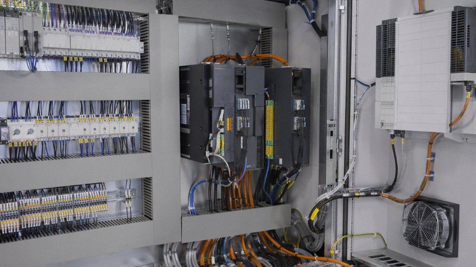
Short answer: no, and the reason goes deeper than convention. Power cables rated 0.6/1 kV with large cross-sections are designed for high current-carrying capacity and voltage stress. Control cables — typically 300/500 V, multi-core, small cross-section, often individually screened — are engineered to carry low-level signals with minimal interference pickup. Run them together in the same trunking and you’re creating a transformer: the power cable’s magnetic field induces noise into unshielded control cores. In practice this shows up as spurious PLC inputs, erratic sensor readings, or nuisance VFD trips. Most panel wiring standards, including IEC 60364-5-51 and EN 60204-1, explicitly require separation. Separate cable routes, separate trunking, minimum 200 mm clearance where they must cross — that’s the working rule on a well-built panel.
How long should industrial cable last, and what actually kills it early?
Correctly specified and properly installed industrial cable has a design service life somewhere in the 25–40 year range, depending heavily on thermal cycling severity, UV exposure, and how rough the installation was. That last point gets underestimated constantly. A cable bent below its minimum bending radius during pull-in — something that happens in a hurry on a Friday afternoon — can damage the insulation immediately or create a stress point that fails two years later under thermal cycling. Thermal overload from under-sized conductors degrades insulation chemistry progressively and irreversibly. Chemical attack from an incompatible jacket compound (PVC outer sheath in a hydrocarbon-rich atmosphere, for instance) causes surface cracking within a few years. Unprotected standard PVC in outdoor UV exposure typically shows brittleness within 5–8 years in high-UV climates. None of these are mysterious failures — they’re all specification or handling errors that were predictable.
Is armored cable always required, or does conduit make it optional?
Armoring serves two functions people often conflate: mechanical crush protection and a dedicated low-impedance earth fault return path through the armor. IEC 60364-5-54 requires that fault current return paths meet specific impedance requirements, and in many industrial installations the armor is how you satisfy that requirement without running a separate earth conductor. Unarmored cable pulled through heavy-duty steel conduit can be acceptable for fixed indoor runs, but only if the conduit joints are properly bonded and the earth continuity through the conduit system is verified and maintained. In my experience, conduit earth continuity degrades over time — a corroded coupler, a loose locknut — so for critical circuits, relying on the conduit alone is a maintenance liability.
What is the difference between LSZH and fire-resistant cable?
These describe completely different properties and the confusion between them causes real safety specification errors. LSZH (Low Smoke Zero Halogen) is a jacket material classification: it tells you what the cable emits when it burns — minimal smoke, no halogen acids. Fire-resistant (FR) cable, tested to IEC 60331, tells you how long the cable continues to function during a fire — typically 30, 60, or 120 minutes of maintained circuit integrity under a flame at 750–950°C. A cable can easily be one without being the other. Emergency lighting circuits, fire alarm wiring, and evacuation system cabling in occupied industrial buildings should be both: fire-resistant construction with an LSZH outer jacket.
A cable labeled LSZH is not automatically fire-resistant and cannot substitute for IEC 60331-compliant cable on emergency circuit applications.True
LSZH describes jacket chemistry only; IEC 60331 fire resistance requires specific construction elements such as mica tape wrapping around conductors, which are absent in standard LSZH cables.
How do VFDs change cable sizing and selection?
VFDs don’t produce clean 50/60 Hz current — the high-frequency switching harmonics increase effective conductor heating above what a standard ampacity table predicts for the same RMS load. A practical working rule is to derate the cable’s current-carrying capacity by roughly 10–15% for dedicated VFD service, though the exact figure depends on the drive’s switching frequency and the cable run length. Beyond sizing, VFDs generate high-frequency common-mode currents that travel back through the motor cable to the drive cabinet. Standard cables don’t contain these well, and the result is bearing erosion in the connected motor and radiated EMI across the plant. VFD-rated cables with symmetrical three-core geometry, a foil layer, and an outer braided shield are the right tool — the symmetry keeps ground return paths balanced and the shielding contains the high-frequency component.
What information does a cable manufacturer actually need to quote accurately?
Incomplete inquiry packages are probably the single biggest source of specification errors and delivery delays in cable procurement. At minimum, a supplier needs: installation method (direct burial, cable tray, conduit, drag-chain, or aerial); ambient temperature range including seasonal extremes; chemical and moisture exposure profile; voltage class and continuous current requirement; applicable compliance standards and certifications required (UL, IEC, HAR, local national code); project location and governing electrical code; required drum lengths or cut lengths; and delivery schedule with any phasing requirements. Providing all of this upfront takes an extra hour. Not providing it costs weeks in back-and-forth clarification, sometimes after incorrect material has already been manufactured.