A buried circuit that was treated like indoor wiring in a trench usually fails at the worst time: after paving, landscaping, production start-up, or handover. Water ingress, crushed insulation, poor joints, and shallow cover turn into nuisance trips, unsafe touch voltages, excavation damage, and expensive rework. The fix is not “bury it deeper and hope”; it is selecting the correct underground-rated cable or raceway system, installing it to code, protecting it mechanically, and testing it before the trench disappears.
Yes, electrical wire can be buried underground, but only if the cable or conduit system is rated for direct burial or wet locations, installed at the required cover depth, protected from mechanical damage, and verified before backfill. Ordinary indoor building wire should not be placed directly in soil.
The part that catches buyers and site teams is that “underground” is not one condition. A garden branch circuit, a factory feeder crossing a yard, a pump supply in wet clay, and a low-voltage cable under a concrete apron all ask for different insulation, armor or conduit, burial depth, warning tape, jointing practice, and inspection discipline.
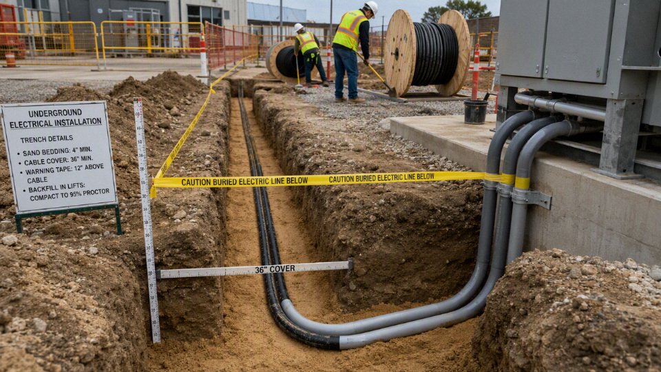
Direct burial versus conduit
Direct burial is usually the lower first-cost choice across open ground when the cable is rated for soil contact and the route is unlikely to be disturbed. Conduit is the safer long-term choice where the run passes through hardscape, vehicle areas, rocky backfill, building entries, or places that may need future replacement or upsizing. The decision is less about “can it be buried?” and more about how much mechanical risk and future access you are willing to buy down.
Direct burial means placing a complete cable assembly, specifically listed or manufactured for direct contact with soil, into a prepared trench. A proper installation is not just “throw the cable in the dirt.” It normally includes suitable bedding, separation from sharp rock or debris, required cover, warning tape above the cable, and mechanical protection at vulnerable points. Depending on jurisdiction and wiring method, common minimum cover can range from roughly 150 mm to 900 mm, with voltage, cable construction, mechanical protection, and local code all affecting the number.
Conduit installation means installing an underground raceway first, then pulling wet-location-rated conductors or a suitable cable through it. The raceway may be PVC, HDPE, galvanized steel, rigid metal conduit, or another approved duct system. In plant work, I’ve seen engineers specify conduit because it “keeps the wire dry.” That is the wrong reason. Underground conduit often collects condensation, groundwater, or water from imperfect fittings, low points, and temperature cycling. The conductors inside still need to be rated for wet locations, and the raceway needs to be treated as a mechanical and routing system, not a waterproof pipe.
Underground conduit should be assumed to be a wet location unless the applicable code, product documentation, and installation conditions prove otherwise.True
This reflects common electrical installation practice: buried raceways frequently accumulate moisture from condensation, groundwater intrusion, or drainage paths. Conductor insulation and cable selection must be verified against the governing electrical code and manufacturer documentation.
Mechanical protection and failure exposure
Conduit improves resistance to the ordinary abuse that kills buried wiring: a skid-steer bucket shaving the trench line, a fence contractor driving a ground rod in the wrong place, angular stone pressing into insulation, rodents chewing jackets, or a later civil crew “finding” the cable with a trenching machine. Rigid steel or galvanized conduit gives stronger impact and crush resistance than PVC or HDPE, but costs more, is harder to install, and may need corrosion evaluation in aggressive soil.
Direct-buried cable relies on the cable construction and the trench quality. Armor, metallic shielding, jacket thickness, bedding sand, burial depth, and warning tape all matter. A tough armored direct-buried cable in clean sand at proper depth may outperform a cheaply installed conduit run with crushed bends and waterlogged boxes. The weak point is often not the middle of the open trench; it is the riser at a pole, the last meter before a pump pad, or the crossing under a driveway where the ground gets compacted and disturbed.
A practical comparison looks like this:
| Decision factor | Direct-buried cable | Conduit-protected conductors or cable |
|---|---|---|
| Mechanical protection | Depends on jacket, armor, bedding, cover, and route discipline | Better protection from impact, compression, rodents, and future digging, depending on conduit material |
| Repair after damage | Usually requires excavation to expose and replace the damaged section | May allow replacement by pulling, if the conduit is intact and not overloaded with bends |
| Installation speed | Faster across clean open ground | Slower due to trench layout, raceway assembly, bends, pulling, and access points |
| Future capacity change | Poor unless spare cable was installed | Better if conduit fill, bend radius, pull boxes, and route were planned properly |
| Moisture control | Cable must be suitable for soil and moisture | Conductors still need wet-location rating; conduit is not a dry environment |
| First cost | Often lower for long simple runs | Often higher up front, especially with rigid conduit, road crossings, and many transitions |
| Lifecycle cost | Best where disturbance risk is low and load is stable | Best where future work, traffic, or upgrade uncertainty is expected |
The mechanism behind the cost difference is straightforward. Direct burial removes raceway material, fittings, many labor steps, and conductor-pulling time. Conduit adds those costs, but it can reduce outage cost later because replacement may be possible without reopening the full route. The trade-off flips once trenching access becomes expensive: under concrete, asphalt, finished landscaping, road crossings, public utility corridors, or a production area where shutdown hours cost more than the cable.
Maintenance and upgrade potential
Conduit only helps future maintenance if it was designed for maintenance. A raceway with too many bends, no pull points, tight fill, collapsed duct, or cheap joints full of silt may be no better than direct burial when a feeder fails. Good conduit routes have sensible sweep bends, accessible pull boxes where allowed, spare duct capacity where future loads are plausible, and documented routing that maintenance people can actually find five years later.
Direct burial is simpler but less forgiving. If a direct-buried feeder faults, crews usually have to locate the fault, excavate, expose the cable safely, and splice or replace it using a method approved for the cable type and environment. That may be acceptable for a long rural pump feeder across open land. It is painful under a warehouse apron where forklift traffic cannot stop and nobody knows whether the spare sleeve shown on the old drawing was ever installed.
For procurement, this becomes a risk question rather than a cable-only question:
- If the load is stable, the route is private, and excavation access will remain easy, direct burial often makes commercial sense.
- If the route crosses pavement, utilities, landscaped customer-facing areas, or future expansion zones, conduit usually earns its cost.
- If future load growth is likely but uncertain, spare conduit or oversized conduit may be cheaper than replacing buried cable later.
- If downtime is expensive, access and replaceability deserve more weight than initial material price.
Where each method is commonly used
Direct burial is commonly appropriate for open routes with predictable conditions and limited mechanical disturbance. Typical examples include:
- Landscape lighting feeders and small outdoor branch circuits, where allowed by local code and cable rating.
- Rural service or feeder runs across private ground with controlled excavation activity.
- Irrigation pump power, especially where the route is long, straight, and outside traffic areas.
- Temporary-to-permanent site utilities, but only where the wiring method is permitted and the final cover, protection, and identification meet code.
- Long private distribution routes where trenching cost dominates and the owner can control future digging through mapping and warning tape.
Conduit is often preferred, and in some places required, at higher-risk sections:
- Building entries, foundation penetrations, and equipment room transitions.
- Driveways, road crossings, loading yards, and other vehicle areas.
- Exposed risers on poles, walls, panels, and equipment pads.
- Rocky soil where bedding alone may not protect the jacket reliably.
- Corrosive industrial zones, after material compatibility is checked.
- Dense utility corridors where future excavation is likely.
- Public-facing or leased sites where the owner cannot fully control later civil work.
Many good installations are hybrid. A cable may be direct-buried across a long open field, then protected in conduit at the pole riser, under the road crossing, into the foundation, and up to the disconnect at the equipment pad. This avoids paying for raceway across every meter while protecting the places where cables actually get damaged. The details matter: transition fittings, bend radius, sealing method if required, corrosion compatibility, and conductor or cable rating must all match the installation.
The boundary on this guidance is code and product approval. A direct-burial cable is not acceptable just because it has a thick jacket, and a conduit route is not acceptable just because it looks protected. Before procurement, confirm the cable rating, conductor temperature class, wet-location suitability, burial depth, warning requirements, grounding method, and any special protection required by the authority having jurisdiction and the equipment manufacturer. Typical low-voltage buried power cables may be 600 V, 0.6/1 kV, or 1.8/3 kV with 70 °C to 90 °C conductor temperature classes, but the correct choice depends on the circuit, load, soil conditions, installation method, and applicable standard.
Cable types for burial
Buried wiring is acceptable only when the cable or conductor system is specifically rated for underground service, wet exposure, mechanical conditions, and the applicable voltage class. Jacket appearance is a poor guide; the useful evidence is in the printed cable marking, datasheet, certification listing, product standard, and manufacturer installation instructions.
Direct-burial feeder and branch-circuit cables
In residential and light commercial work, direct-burial feeder cable is often used for garage feeders, yard lighting, small pump circuits, outbuildings, gates, and similar loads where local code recognizes that cable assembly for underground feeder service. In North American practice, UF-type assemblies are a familiar example; in IEC-style markets, the product names differ, and buyers should verify the relevant national standard rather than assuming equivalence from the words “underground cable.”
What makes these cables different is not just a thicker jacket. A proper direct-burial assembly must tolerate soil moisture, long-term insulation stress, temperature cycling, and some degree of handling damage during installation. It still may need sand bedding, warning tape, marker posts, or conduit sleeves at risers, road crossings, and building entries. The trade-off is simple: direct burial saves conduit cost and installation time, but it is less forgiving when a circuit must be replaced, upsized, or diagnosed after landscaping and pavement are finished.
Wet-location conductors in underground conduit
Underground conduit should be treated as a wet raceway, even if it looks dry on the day it is installed. Condensation, groundwater migration, leaking handholes, and seasonal frost movement put moisture inside the raceway sooner or later. Single conductors pulled through underground conduit therefore need insulation types approved for wet locations by the governing code and product standard, not dry-location building wire that happened to fit through the pipe.
The design check is not only “will it fit.” A proper conduit installation should verify:
- conductor insulation type and wet-location approval;
- voltage rating, commonly 600 V in many building systems, or project-specific low-voltage ratings such as 0.6/1 kV;
- conduit fill against the local rule or standard;
- allowable pulling tension and sidewall pressure, especially on long runs with several bends;
- lubricant compatibility with the cable jacket or insulation;
- bend radius at sweeps, handholes, and terminations;
- termination temperature rating, often the limiting point even when the cable insulation is rated higher;
- grounding or bonding method, including metallic conduit continuity where used.
A cable can fail early because of installation damage long before the insulation compound itself reaches its thermal limit. Tight pulling around a cheap 90-degree elbow, a burr at a cut conduit end, or a maintenance crew using fish tape like a winch can nick insulation badly enough to show up later as nuisance trips or low insulation resistance.
Low-voltage power cables for sites, plants, and outdoor distribution
For buildings, factories, renewable energy sites, pumps, lighting networks, and outdoor distribution, buried low-voltage power cables are commonly supplied in ratings such as 600 V, 0.6/1 kV, or 1.8/3 kV, with conductor temperature classes typically around 70 °C to 90 °C depending on insulation and standard. Those numbers are not interchangeable purchasing shorthand; they affect conductor sizing, allowable ampacity, short-circuit withstand, accessories, and termination selection.
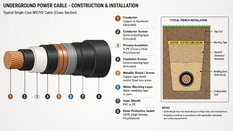
Typical construction choices include copper or aluminum conductors, XLPE insulation, PVC or PE outer sheaths, metallic armor where needed, water-blocking tape, and filling compounds. Copper gives smaller conductor size and better tolerance of rough termination practice, but it costs more and is attractive to theft. Aluminum is commercially sensible on larger feeders, yet it needs correct lugs, oxide control, torque discipline, and allowance for larger cable diameter. In plants where electricians rotate between contractors, I usually prefer to make aluminum termination instructions almost painfully explicit on the drawing package.
XLPE insulation is widely used because it handles heat and electrical stress well. PVC sheathing is common and economical, with good general handling characteristics; PE sheathing usually gives stronger moisture and abrasion performance but can be less flame-retardant depending on compound. LSZH compounds may be specified where smoke and halogen acid gas are a concern, but that requirement is more common in tunnels, enclosed public areas, offshore modules, or certain industrial facilities than in ordinary soil burial.
The color of an electrical cable jacket proves whether it is suitable for direct burial.False
Jacket color may reflect a manufacturer convention, circuit function, national practice, or customer specification. Burial rating, voltage class, temperature rating, and code acceptance must be confirmed from markings, datasheets, certifications, and installation instructions.
Armored, steel tape armored, and industrial buried cables
Armored cable is chosen when the buried circuit faces crushing, impact, rodent attack, digging damage, or rough industrial handling. Steel tape armor, steel wire armor, aluminum wire armor, or other metallic protection can make sense around substations, process areas, ports, mines, logistics yards, and renewable energy collector networks where the ground is full of old concrete, rebar, forklifts, drainage work, and future excavation surprises.
Armor is not magic. It adds diameter, weight, bending stiffness, pulling load, termination complexity, and cost. It may also require bonding, grounding, corrosion protection, and correctly rated glands. In wet or chemically aggressive soil, the outer sheath over the armor becomes critical; bare or poorly protected metallic armor can corrode until the cable loses the very protection it was bought for. Armored cable is a mechanical-risk decision, not a substitute for selecting the correct insulation, voltage rating, moisture protection, and installation depth.
Medium-voltage underground cable basics
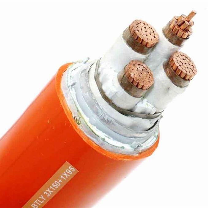
Medium-voltage underground cable is a different class of work from ordinary branch circuits. A typical MV cable may include a conductor, conductor screen, XLPE or EPR insulation, insulation screen, metallic shield or concentric neutral, water-blocking elements, and an outer jacket. Each layer controls electrical stress, moisture migration, fault current path, or mechanical protection.
The mechanism matters. At medium voltage, electric field concentration at voids, cuts, shield discontinuities, or poorly made terminations can produce partial discharge and progressive insulation damage. That is why MV cable selection must be matched with shield bonding, compatible elbows or terminations, factory-approved accessories, trained jointing labor, and test requirements such as insulation resistance, withstand testing, sheath testing, or partial discharge testing where specified by the project standard. The boundary is clear: once the installation enters MV territory, do not buy cable as a commodity line item without the termination system and test plan attached.
Control, instrumentation, communication, and fiber optic cables underground
Not every buried cable carries power, but underground conditions still punish weak construction. Control cable may need wet-location insulation and suitable voltage rating because it can carry operational power for coils, solenoids, or interlocks. Instrumentation cable is often judged by signal integrity: shielding, pair twisting, capacitance, drain wire construction, and separation from power circuits matter as much as jacket toughness. Communication and fiber optic cables need moisture blocking, crush resistance, tensile strength for pulling, and sometimes rodent protection.
A few cable types should not be buried directly:
- indoor non-metallic sheathed cable not rated for wet or underground use;
- dry-location building wire installed directly in soil;
- ordinary flexible cord used as a permanent underground feeder;
- damaged cable with jacket cuts, crushed sections, or unknown insulation condition;
- unmarked surplus cable with no traceable datasheet or certification;
- any cable lacking burial approval or wet-location approval for the actual installation method.
The safest procurement habit is to specify the service environment first: soil burial or wet conduit, voltage, conductor material, armor requirement, sheath compound, flame or smoke requirement if applicable, pulling route, termination type, and governing standard. Once those are fixed, jacket color can be treated as identification only, not evidence.
Depth, routing, and protection
A buried circuit usually fails because the installation around the cable was treated as dirt work instead of electrical work. Depth, bedding, route marking, bending control, and protection at risers determine whether the same circuit is still safe after settlement, forklift traffic, landscaping, drainage repairs, and the first careless excavation five years later.
Minimum cover is not one universal number. In practice, common minimum cover requirements run from roughly 150 mm to 900 mm, depending on jurisdiction, voltage, wiring method, mechanical protection, location type, and whether the work is residential, commercial, industrial, agricultural, or utility-related. Always verify against the applicable local electrical code, utility specification, and project drawings; “we always bury it this deep” is not a defensible design basis.
Typical planning categories look like this:
| Installation situation | Depth and protection planning logic |
|---|---|
| Shallow low-voltage landscape circuits | Often permitted at relatively shallow cover only when voltage, cable type, and protection method allow it. Vulnerable to spades, edging tools, and irrigation repairs. |
| Protected residential branch circuits | Usually planned deeper than landscape wiring, with conduit or direct-burial cable selected according to code and maintenance expectations. |
| Feeders to garages, pumps, gates, or outbuildings | Need more conservative routing, voltage drop review, and protection where they emerge from the ground. |
| Service laterals | Often controlled by utility or service rules, not just the site electrician’s preference. Marking and as-built accuracy matter because future excavation risk is high. |
| Road, driveway, and yard crossings | Require attention to compaction, sleeves, duct banks, or other mechanical protection because wheel loads and settlement change the trench environment. |
| Agricultural land | Depth must account for plowing, ripping, drainage tile work, livestock areas, and seasonal soil movement. |
| Industrial distribution routes | Usually need coordinated corridors, separation from process piping, access roads, foundations, cable pulling limits, and future plant expansion plans. |
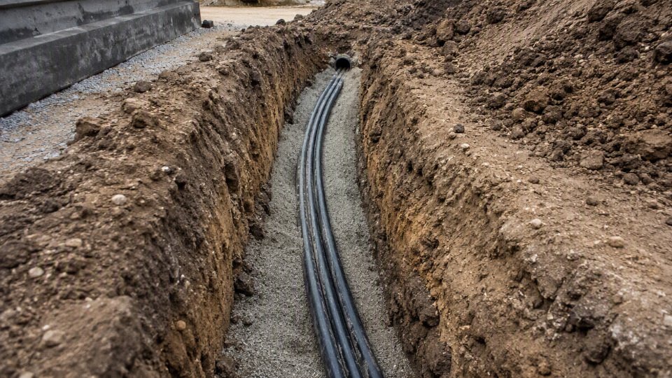
Trench preparation is where many “good cable, bad installation” failures start. The trench bottom should be shaped so the cable or conduit is continuously supported, not suspended between hard lumps of rock. Remove sharp stones, broken concrete, scrap steel, and demolition aggregate. Where the specification calls for sand or screened bedding, use it, and keep it clean. A 20 mm stone sitting under a loaded direct-buried cable can create point pressure that slowly damages the jacket, especially after soil settlement and thermal cycling.
Drainage is not just a civil detail. If a trench becomes a long water channel toward a building wall, manhole, or equipment plinth, the electrical route may stay wet for years. Many underground cables are designed for wet locations, but water still changes thermal behavior, corrosion risk for metallic components, and maintenance conditions. Where slope, drainage layer, or duct sealing is specified, do not let the excavation crew “fix it later” with random backfill.
Route planning should be boring on purpose. A straight, documented, accessible route is better than a clever route that saves six meters and crosses every service in the yard. Priorities should include:
- The shortest safe route that avoids known future construction zones.
- Accessible inspection points, pull boxes, handholes, or manholes where required.
- Separation from gas, water, drainage, communication, steam, and other electrical services according to code and utility requirements.
- Avoidance of tree roots, retaining walls, unstable slopes, and areas likely to be regraded.
- Coordination with foundations, fence lines, loading bays, rail tracks, fuel areas, and stormwater works.
- Practical excavation access for repair, not just initial installation.
Warning and identification measures are cheap compared with one damaged feeder. Warning tape should be installed above the cable or duct at the specified height, not thrown into the trench just before final grading. Marker posts, route tiles, detectable tape, tracer wire for non-metallic conduit systems where appropriate, and durable labels at terminations all help the next crew understand what is below ground. As-built drawings must show actual route deviations, depths at critical points, sleeve locations, handholes, and crossings. A drawing that shows the design route after the installer shifted around a storm drain is worse than no drawing because it gives false confidence.
Physical protection deserves special attention at transitions. Cables emerging from soil are exposed to mowers, pallets, sun, hand tools, rodents, and bored operators with forklifts. Use suitable conduit sleeves, rigid risers, bushings, guards, slabs, duct banks, or concrete encasement where the mechanical risk justifies it. Expansion allowances matter at building entries and long exposed risers because soil, conduit, and structures do not move together. A sharp conduit edge without a bushing can damage a jacket during pulling, then finish the job slowly as the cable expands and contracts in service.
Backfill should maintain cable position and remove future point loads. Place initial backfill gently, keep sharp aggregate away from the jacket, compact in appropriate layers, and avoid voids that later collapse under vehicle loads. Heavy equipment should not cross the trench until there is enough cover and compaction to distribute the load. I have seen trenches look perfect at inspection and then get ruined by one skid steer crossing diagonally before the bedding was locked in.
Installation handling is part of protection too. Observe the cable manufacturer’s minimum bending radius, maximum pulling tension, sidewall pressure limits, installation temperature range, and drum handling instructions. Cold jackets can stiffen and crack more easily. Overspun drums, sideways rolling, crushed flanges, and pulling with a backhoe because “it only needs another meter” are the sort of habits that create faults nobody finds until after backfill. For longer runs, calculate pulling loads and use proper rollers, lubricants, pulling eyes, swivels, and staged pulls where needed.
Deeper burial is not automatically safer. More cover can reduce casual digging damage and surface loading, but excessive depth increases excavation cost, repair time, pulling difficulty, water exposure, heat dissipation uncertainty, and the chance that future crews will not expect the circuit at that level. For loaded power cables, the thermal path through soil matters; wet clay, dry sand, compacted fill, and duct banks do not behave the same. The preferred depth stops being “as deep as possible” once maintainability, thermal rating, code compliance, and future excavation control become worse than the extra mechanical protection gained.
Soil, water, and heat
Underground electrical design is not just a burial-depth exercise; it is a soil, water, and heat-management problem. A cable that is perfectly acceptable on a tray can fail early in a trench if the jacket, insulation system, splice kit, conduit layout, and thermal assumptions do not match the ground conditions around it.
In design reviews, I normally treat buried circuits as being in a wet or at least damp environment unless there is strong evidence otherwise. Trenches collect water. Conduits breathe through temperature cycling. Handholes flood after one bad storm. Duct banks pick up condensation even when the route looks dry in summer. Seasonal groundwater movement can turn a neat excavation into a wet clay channel by spring.
Water is not only a leakage problem
Water-related failures are often slow at first, then sudden at energization or under load. The weak point may not be the middle of the cable; it is often a splice, gland, termination, damaged sheath, or a place where someone pulled too hard around a bend.
Common water-driven mechanisms include:
- Insulation swelling or softening: Some polymer systems tolerate moisture better than others, but incompatible insulation or jacket materials can absorb water, change dimensions, lose mechanical strength, or become easier to damage during thermal cycling.
- Conductor corrosion: Copper and aluminum conductors are not immune if moisture reaches the metal through a cut end, poor lug seal, or capillary path under the insulation. Aluminum is especially unforgiving where moisture and dissimilar metals meet.
- Armor, screen, and shield corrosion: Steel wire armor, metallic tape shields, concentric neutrals, and copper screens can corrode if the outer sheath is damaged or if groundwater chemistry is aggressive.
- Electrical tracking: Contaminated moisture across insulation surfaces can create conductive paths, especially at terminations, inside damp boxes, and around dirty support hardware.
- Water treeing in certain insulation systems: Medium-voltage and some higher-stress cable systems are vulnerable to microscopic tree-like degradation when moisture, electrical stress, and insulation imperfections coincide. Material choice, shield design, manufacturing quality, and test regime matter here.
- Termination breakdown: Moisture changes surface resistance and can defeat creepage distance assumptions. Poor heat-shrink work, wrong mastic placement, or an enclosure that “almost” seals will eventually show up as nuisance tripping, partial discharge, or failure.
The practical rule is simple: buried cable accessories must be selected and installed as waterproof electrical components, not as ordinary indoor joints wrapped a little better. That means approved splice and termination kits, correct crimping or compression tools, clean cable preparation, stress control where required, and enclosure ratings suitable for the location. I have seen good cable blamed for failures that started with a cheap lug, a dull insulation knife, or a heat-shrink sleeve overheated on one side and barely recovered on the other.
Soil chemistry can shorten service life
Soil chemistry is easy to ignore because it is out of sight after backfill. It should not be. Aggressive ground can attack metallic armor, shields, grounding conductors, conduit, and even some sheath materials over time.
The main chemical risks are:
- Acidic or alkaline soil: pH outside a normal range can accelerate corrosion of metals and degrade some protective systems.
- Chlorides: Coastal sites, de-icing salt areas, and saline groundwater are hard on metallic components.
- Sulfates: Common in some soils and industrial areas; they can contribute to corrosion and attack surrounding civil materials.
- Hydrocarbons: Fuel, oil, solvents, and contaminated ground near maintenance yards or old process areas can soften or swell unsuitable jackets.
- Fertilizers and agricultural chemicals: Rural cable routes through farmyards or greenhouse areas may see nitrates, ammonia compounds, and seasonal chemical exposure.
- Industrial contamination: Ash, slag fill, plating waste, process runoff, and unknown reclaimed land need testing rather than guessing.
- Stray current corrosion: Nearby DC systems, rail, cathodic protection installations, or poorly bonded grounding networks can drive corrosion in buried metallic parts.
- Aggressive groundwater: Moving water can carry oxygen and dissolved salts continuously to damaged sheath areas, so the attack does not stop after the first wet season.
For ordinary commercial jobs, a visual soil review and knowledge of the site history may be enough to trigger better sheathing, conduit, or corrosion protection. For plants, substations, ports, mines, and chemical sites, soil resistivity, pH, chloride/sulfate content, and contamination history are worth checking before procurement is locked.
Soil movement and mechanical damage are design loads
The ground is not a passive support. It moves, settles, freezes, dries, swells, and gets compacted by people who may not know a cable is there.
Mechanical risks worth designing around include:
- Sharp rock and construction debris: These can point-load a sheath during backfill or later settlement. Screened sand bedding or selected backfill is cheap compared with fault locating after paving.
- Expansive clay: Wet-dry cycles can bend and squeeze cable routes, especially near building edges and poorly drained trenches.
- Frost heave: In cold regions, freezing soil can lift and shift ducts, pull on elbows, and stress entries into buildings.
- Settlement and poor compaction: A trench that sinks creates bending and shear at rigid transitions such as manholes, poles, foundations, and duct bank ends.
- Vibration: Routes near presses, crushers, rail tracks, or heavy truck lanes need more mechanical protection than a quiet landscaped area.
- Burrowing animals and roots: Rodents, insects, and roots exploit gaps around entries, ducts, and soft backfill zones.
- Vehicle crushing loads: Depth helps, but cover alone may not protect a cable under forklifts, container yards, mobile cranes, or repeated truck traffic.
Pest and rodent resistance is usually handled by combining methods rather than trusting one feature. Armor, tougher outer sheaths, rigid ducting, careful route selection, sealed building entries, screened bedding, and site sanitation all help. Keeping grain, food waste, packaging, and warm open penetrations away from cable entries sounds like housekeeping, but it affects electrical reliability.
Heat underground is easy to underestimate
Buried cable ampacity depends on more than conductor size. The heat path runs from conductor to insulation, through sheath or conduit, into surrounding soil, then outward into the ground mass. Anything that raises thermal resistance in that path raises conductor temperature.
Key variables include:
| Factor | Why it changes buried-cable temperature |
|---|---|
| Conductor size and material | Larger conductors usually reduce electrical losses, but they still need a path to reject heat. |
| Insulation temperature rating | Common low-voltage buried power cables may use 70 °C or 90 °C conductor classes, depending on cable type and approval. The connected equipment terminals may have lower limits. |
| Load profile | A cable carrying high continuous current runs hotter than one with intermittent motor or diversity loads. |
| Soil thermal resistivity | Dry sand, ash fill, and some compacted materials can be poor heat conductors compared with moist native soil or engineered thermal backfill. |
| Burial depth | Deeper installation may improve mechanical protection but can reduce heat dissipation because the cable is farther from temperature-swinging surface soil. |
| Cable spacing and grouping | Closely spaced circuits heat each other. Multiple loaded conduits in one duct bank can require significant derating. |
| Conduit material and fill | Air gaps inside conduit and dense grouping can trap heat compared with a single direct-buried cable in suitable bedding. |
| Ambient earth temperature and moisture | Seasonal ground temperature and drying around a hot cable affect sustained ampacity. |
The counter-intuitive failure is a cable that is electrically oversized on paper but still overheats underground. That can happen when several feeders are grouped in conduit, surrounded by dry thermal backfill, buried deeper than assumed, and operated near full load for long periods. Upsizing copper or aluminum reduces I²R losses, but if the installation blocks heat rejection, temperature can still climb beyond the insulation or termination limit.
Larger industrial and utility projects deal with this using engineered thermal backfill, duct spacing, derating factors, load diversity studies, and sometimes temperature monitoring. The trade-off is cost and space: wider duct banks, special backfill, and spare conduits improve thermal margin and maintainability, but they increase excavation width, civil work, and coordination with drainage, foundations, and roads. The preferred choice flips when continuous load, poor native soil, or high consequence of outage makes thermal margin more valuable than saving trench width.
This thermal discussion stops being reliable when site inputs are unknown. To estimate buried cable ampacity responsibly, the designer needs the circuit loading, cable construction, conduit arrangement, spacing, burial depth, soil thermal resistivity, expected ground temperature, and any applicable code or project derating rules. Without those, an ampacity figure is just a guess with units attached.
Codes, permits, and records
A buried electrical circuit is not legal just because the cable is rated for soil contact or installed at a sensible depth. The installation has to match the code, permit, inspection, utility, and documentation requirements for that exact location, building use, voltage level, and authority having jurisdiction. Always settle those requirements before trenching, not after the cable is already under compacted backfill.
Electrical rules vary more than buyers sometimes expect. A farm pump feeder, an airport lighting circuit, a residential outbuilding supply, a refinery cable run, and a factory yard distribution circuit can all have different approval paths even at similar voltages. Country and regional code families may reference IEC, NEC, UL, CSA, BS, EN, or local national standards, but the enforceable rule is the one adopted by the project jurisdiction and, where connected to a network, the utility specification. One site may allow a listed direct-burial cable at a given cover; another may require duct, warning tape, marker posts, concrete encasement, or utility witness inspection.
Common approval topics include:
- Approved cable or conductor type: insulation, sheath, voltage rating, wet-location suitability, armor, metallic screen, and direct-burial listing where applicable.
- Minimum cover and mechanical protection: depth, road crossings, vehicle areas, rocky soil, warning tape, slabs, tiles, or conduit transitions at risers.
- Overcurrent protection: breaker or fuse rating matched to conductor ampacity, installation method, ambient conditions, grouping, and fault level.
- Grounding and bonding: equipment grounding conductor, metallic raceway bonding, sheath bonding, grounding electrodes, and touch-voltage control on larger systems.
- Ground-fault protection: required in some occupancies, outdoor circuits, special equipment, marinas, agricultural areas, or personnel-protection applications.
- Disconnecting means and isolation: accessible switching for buildings, pumps, signs, chargers, and remote equipment.
- Raceway material and fill limits: PVC, HDPE, steel, concrete-encased duct, bend radius, pulling tension, fill percentage, and spare duct requirements.
- Inspection timing: what must remain visible before backfill, and which tests are required before energization.
The permit sequence usually starts with a design review where the authority or client requires one. Before excavation, the contractor should contact the local utility locating service and mark the route in the field. Do not assume the public locator marks everything: private feeders, old yard lighting, irrigation controls, cathodic protection leads, security cables, and abandoned-but-still-energized circuits are often outside the public locate scope. On older industrial sites, I like a second pass with facility maintenance and old drawings; the person who remembers the 1998 compressor shed addition can save a crew from a bad afternoon.
A typical compliant workflow looks like this:
- Submit drawings, load data, protection details, and cable specifications where review is required.
- Locate public utilities and separately identify private underground services.
- Excavate, bed, route, and support the cable or raceway according to the approved method.
- Hold trench inspection before backfill if the authority, utility, engineer, or client requires it.
- Perform continuity, insulation resistance, grounding, polarity, and voltage drop checks as applicable before energization.
- Record terminations, splices, torque values where specified, and any field deviations.
- Complete final inspection and receive energization approval before placing the circuit into service.
Keep the project file boring and complete. It should include cable datasheets, certificates, batch and drum numbers, route drawings, trench depth notes, test reports, termination records, splice locations, photographs before backfill, warning tape or marker details, and maintenance access points. For larger plants, tie the route into the site drawing system rather than leaving it in a contractor’s closeout binder that nobody opens again.
Good records pay back later. They shorten fault finding, support warranty claims, help engineers plan expansions without cutting into live services, and give safety auditors or insurers something better than guesswork after an incident. The real test of an underground installation is not only whether it energizes today; it is whether another qualified person can understand, inspect, isolate, and repair it years from now.
Installation defects and warning signs
Most unsafe underground wiring is not caused by the soil itself; it starts with the wrong cable, a bad transition, or an installation shortcut that gets hidden before anyone tests it. The early symptoms are usually nuisance trips, voltage problems, moisture-related outages, or heat at accessible terminations, and they should be treated as fault evidence rather than normal electrical “annoyance.”
Common installation defects I look for first are the simple ones, because they are the ones that get buried quickly and become expensive to prove later:
- Indoor cable buried outside: dry-location cable assemblies and building wire not listed for wet underground use can absorb moisture, lose insulation resistance, and fail without visible damage at the surface.
- Extension cords used as permanent wiring: flexible cords are not underground feeders. Jackets get cut, plugs corrode, and nobody has a proper equipment grounding path or strain relief.
- Unapproved underground splices: taped joints, wire nuts in soil, or non-gel-filled boxes are failure points waiting for rainwater and freeze-thaw movement.
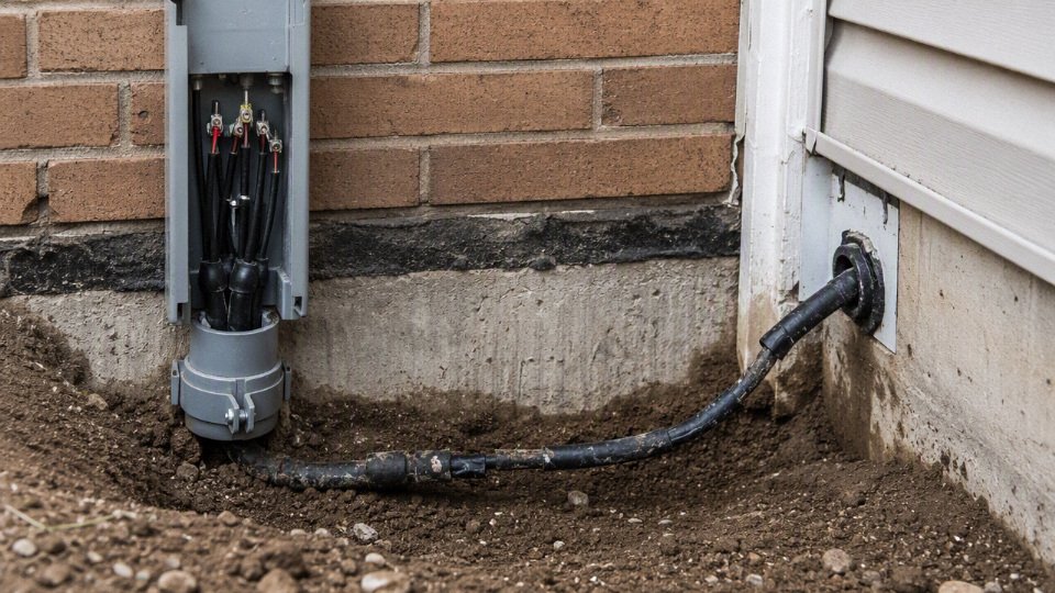
- No conduit at risers: where cable comes out of the ground into a panel, wall, pole, pump skid, or gate operator, it needs mechanical protection. String trimmers, shovels, forklifts, and UV exposure are not theoretical hazards.
- Shallow burial or poor routing: a cable may work electrically on day one and still be unsafe if it sits in the normal path of trenching, edging, fence posts, or vehicle rutting.
- Damaged insulation pulled into service: a nick from a pulling grip, conduit burr, or trench rock can become a wet-ground leakage path months later.
- Backfill with sharp debris: broken concrete, scrap metal, crushed rock, and construction waste can point-load the jacket as the soil settles.
Design defects show up as nuisance operation or premature heating rather than immediate failure. Watch for undersized conductors, missing equipment grounding conductors, wrong breaker or fuse sizing, excessive voltage drop on long runs, incompatible aluminum-to-copper or fine-strand terminations, overfilled conduit, and no derating where several loaded circuits share a raceway or where loads run continuously. A pump motor that starts hard at the far end of a long buried feeder may not have a “motor problem” at all; it may be seeing low voltage because the feeder was sized only for ampacity, not voltage drop.
Environmental defects are just as important:
- Cable not rated for wet locations, even if it is inside underground conduit.
- Jacket material unsuitable for oils, fuels, fertilizer, solvents, or process chemicals.
- Metallic armor or shielding left unprotected in corrosive soil.
- No rodent protection in areas where chewing damage is common.
- Poor sealing at wall penetrations, duct banks, handholes, or building entries, allowing water migration into equipment.
Warning signs deserve quick action when they repeat or appear after weather or excavation. Typical symptoms include:
- Breakers or fuses tripping without an obvious load change.
- GFCI or RCD trips, especially after rain.
- Flickering lights, weak motors, or contactors chattering.
- Measurable voltage sag at the load end.
- Warm disconnects, panels, plugs, or terminations.
- Burning odor near junction boxes, pedestals, or equipment terminals.
- Outages that appear after flooding, irrigation, or heavy rain.
- Freshly disturbed landscaping near the cable route.
- Cable, conduit, warning tape, or splice boxes becoming visible at grade.
Qualified personnel normally diagnose buried circuits in stages: visual inspection of accessible points, continuity checks, insulation resistance testing, grounding and bonding verification, polarity checks, voltage drop measurement under load, sheath or jacket testing where applicable, time-domain reflectometry for fault distance estimation, and thermal imaging of accessible terminations. The test choice depends on cable type, voltage class, connected equipment, and whether the circuit can be safely isolated; insulation resistance testing, for example, must not be applied blindly across sensitive electronics.
De-energize the circuit and call a licensed electrician or qualified engineer after excavation damage, flooding, repeated trips, exposed conductors, shock sensation, burning smell, or suspected underground splice failure. Many underground failures begin at interfaces: risers, bends, handholes, splices, terminations, and transitions between direct burial and conduit. That is where water stops, stress concentrates, rodents enter, pulling damage hides, and maintenance crews make the “temporary” repair that becomes permanent.
Bulk cable procurement requirements
A useful underground cable quotation starts with the installed duty, not just a cable name and length. Buyers should define the electrical load, burial method, environment, applicable standard, and inspection documents before asking for price, because small omissions at purchase stage can become expensive trench rework, failed tests, or shipment disputes later.
For contractors, distributors, EPC teams, utilities, and plant owners, the purchasing file should lock down the cable construction first:
- Voltage rating: 600 V, 0.6/1 kV, 1.8/3 kV, or another project-specific class.
- Conductor material: copper or aluminum, including required class and flexibility.
- Conductor size: based on load current, voltage drop, fault duty, installation conditions, and derating.
- Core count: single-core, two-core, three-core, four-core, multi-core, or with grounding conductor.
- Insulation material: such as XLPE, PVC, EPR, or another specified compound.
- Outer sheath material: selected for soil contact, moisture, chemicals, sunlight exposure at risers, and abrasion.
- Armor type: steel wire, steel tape, aluminum armor, or unarmored construction where conduit provides protection.
- Screen or shield requirements: especially for medium-voltage circuits or interference-sensitive installations.
- Flame performance: needed where the cable enters buildings, tunnels, trays, substations, or industrial rooms.
- Temperature rating: commonly 70 °C or 90 °C conductor class for low-voltage buried power cable, but verify against the actual standard and installation method.
- Burial method: direct burial, duct bank, PVC conduit, HDPE conduit, steel sleeve at crossings, or mixed routing.
The project environment then decides whether that construction is enough. Procurement should state:
- Soil type: sand, clay, rocky backfill, corrosive soil, made ground, or thermally poor dry soil.
- Water exposure: occasional damp soil, seasonal flooding, high water table, submerged duct, or drainage failure risk.
- Chemical exposure: hydrocarbons, fertilizers, acids, alkalis, salt, wastewater, or process-area contamination.
- Rodent and termite risk.
- Mechanical load: foot traffic, light vehicles, forklifts, road crossings, compacted backfill, or future excavation risk.
- Installation temperature and minimum bending conditions during pulling.
- Expected service life.
- Route length, pulling section lengths, and elevation changes.
- Direct burial versus conduit or duct bank.
- Termination system, gland type, lugs, joints, and equipment entry details.
Low unit price is often the least reliable buying metric for buried cable. A cheaper cable can cost more if the sheath is not suitable for wet locations, markings do not match the purchase order, drum traceability is weak, or the construction has not been tested to the claimed standard. The mechanism is simple: underground failure is expensive because the defect is hidden after backfill, so the cost moves from the cable invoice to locating, excavation, downtime, jointing, and retesting.
Buyers should request compliance evidence before production or shipment, not after a dispute. The document pack may include:
- Applicable manufacturing standards and destination compliance requirements.
- Product certificates where required.
- Type test reports for the cable design.
- Routine test records for the supplied batch.
- Factory test reports.
- Quality management credentials.
- Drum identification and cable marking details.
- Batch traceability from raw material to finished drum.
- Packing list, drum schedule, gross weight, dimensions, and handling marks.
- Export packaging details, including protection against moisture, impact, and long storage.
- Documentation language required by the project or customs authority.
Commercial terms matter as much as construction. Confirm minimum order quantity, production lead time, partial-shipment options, delivery schedule, drum size limits for site handling, container loading plan, inspection hold points, third-party inspection needs, destination standards, and after-sales technical support. A drum that is too heavy for the site forklift or too large for the cable trench route can create a very ordinary but very costly field problem.
This does not mean every project needs the heaviest armor, highest voltage class, or most expensive sheath. The preferred choice flips when the circuit is short, accessible, inside a protected duct, and easy to replace. It flips back toward a more robust cable when the route is long, wet, chemically exposed, under traffic, or tied to production equipment where outage cost is high.
Jinda’s procurement relevance is scale and project support: established in 1987, with five production bases in China, 470,000 m² of manufacturing space, more than 1,000 employees, and supply experience in more than 50 countries. Its integrated R&D, production, sales, technical support, and after-sales service structure is useful for buyers who need cable selection, bulk supply coordination, and documentation control rather than a one-line commodity quote.
For a serious quotation, share the load data, route length, installation method, soil and water conditions, target standards, termination details, drawings, and any project specification. With those inputs, the manufacturer can recommend a suitable underground cable construction and confirm what evidence, packaging, and delivery arrangement can be supplied.
Frequently asked questions
Can any electrical wire be buried underground?
No. Only cable or insulated conductors specifically rated for underground, wet-location, or direct-burial service should be installed below grade. Ordinary building wire, appliance cord, and indoor-sheathed cable can absorb moisture, lose insulation resistance, or fail mechanically in soil.
Do direct-burial cables still need conduit?
Sometimes. A direct-burial cable may be allowed in soil without continuous conduit, but conduit is still commonly used at risers, building entries, road crossings, high-traffic zones, rocky trench sections, and locations where future replacement matters. In practice, I like conduit anywhere a shovel, forklift tine, fence post auger, or landscaper is likely to find the route later.
How deep should underground electrical cable be buried?
Common minimum cover can range from about 150 mm to 900 mm, depending on voltage, wiring method, mechanical protection, surface use, and local code. A residential garden circuit, an industrial feeder under traffic, and a service crossing below a paved yard are not the same design problem. Always verify the required depth against the applicable electrical code and project drawings before trenching.
Can indoor cable be used if it is placed inside conduit?
Usually no, unless the cable or conductors are also rated for wet locations and permitted by the local code for that raceway installation. Underground conduit is treated as a wet environment because water enters through joints, condensation, pull boxes, and temperature cycling. “Inside conduit” does not magically convert dry-location cable into underground cable.
Is underground conduit waterproof?
No underground conduit system should be assumed waterproof. PVC, HDPE, steel, and other conduit systems can protect against crushing and abrasion, but moisture still gets in through fittings, transitions, damaged joints, and condensation. The conductors or cable inside must be suitable for wet conditions.
What is the best cable for outdoor underground power?
The best choice depends on voltage, load current, soil conditions, installation method, fault protection, and local approval requirements. Typical low-voltage buried power cables are specified around 600 V, 0.6/1 kV, or 1.8/3 kV ratings, with conductor temperature classes often in the 70 °C to 90 °C range. For industrial feeders, the jacket material, armor option, water resistance, conductor material, and voltage drop can matter as much as the voltage rating printed on the sheath.
Can I bury an extension cord for permanent use?
No. Extension cords are temporary-use products, not permanent underground wiring. Buried cords are easily damaged, are not designed for long-term soil moisture exposure, and create a serious shock and fire risk. If power is needed permanently, install a code-compliant underground circuit with proper cable, protection, grounding, and inspection.
What should I do if I hit a buried electrical cable?
Stop work immediately, keep people away, and do not touch the cable, tool, machine, or wet soil near the strike. De-energize the circuit if it can be done safely from a known disconnect, then call a qualified electrician or utility contact. Even if there is no spark or trip, the insulation may be cut and unsafe to re-energize.
How long does underground electrical cable last?
Service life varies widely with cable construction, soil chemistry, water exposure, thermal loading, installation damage, splices, and operating current. A correctly selected and installed buried cable can serve for decades, but poor backfill, sharp stones, overloaded conductors, water-filled splices, or unrecorded repairs can shorten life sharply. Insulation resistance testing and visual inspection of accessible terminations are better indicators than age alone.
What information should I provide when requesting a buried cable quotation?
Provide enough detail for the supplier to quote the cable you actually need, not just a nominal size.
- System voltage and phase arrangement
- Load current, circuit length, and acceptable voltage drop
- Installation method: direct burial, conduit, duct bank, tray-to-burial transition, or armored cable
- Required standard, code, or project specification
- Conductor material and size, if already determined
- Insulation, sheath, armor, and flame or water-resistance requirements
- Soil conditions, ambient temperature, and expected burial depth
- Drum length, marking, packaging, inspection, and document requirements
- Destination country, project schedule, and quantity by size/type
Verify your burial specification
Underground electrical wiring is acceptable only when the cable construction, wiring method, protection, depth, testing, and records all match the local code and the actual site conditions. A cable that is perfectly adequate in a dry residential garden may be the wrong purchase for a waterlogged industrial yard, a solar farm trench, or a mine feeder exposed to crushing, chemical attack, and long route voltage drop.
Before issuing a purchase order or opening a trench, check the specification as a system, not as a line item that says “copper cable” or “aluminum cable.” At minimum, confirm:
- Approved cable marking
- Direct-burial, wet-location, armored, screened, or conduit-use marking as required.
- Applicable standard, certification mark, voltage grade, conductor material, insulation, sheath, and production identification.
- Voltage rating and ampacity
- Match 600 V, 0.6/1 kV, 1.8/3 kV, or higher project requirements as applicable.
- Derate for soil thermal resistivity, grouping, conduit fill, ambient conditions, and continuous load profile where required.
- Moisture and environmental resistance
- Confirm whether the cable is suitable for permanent wet ground, seasonal flooding, chemicals, fertilizers, hydrocarbons, salt, rodents, or UV exposure at risers.
- Burial depth and mechanical protection
- Verify the required cover, commonly somewhere between about 150 mm and 900 mm depending on code, voltage, traffic exposure, and wiring method.
- Decide whether conduit, duct bank, warning tape, concrete cover, armor, or marker posts are needed.
- Route separation
- Maintain required clearance from gas, water, drainage, telecom, heat sources, foundations, tree roots, and future excavation zones.
- Grounding and overcurrent protection
- Confirm protective conductor sizing, bonding, earth fault path, breaker or fuse rating, RCD/GFCI requirements, and fault-clearing performance.
- Splices, joints, and terminations
- Avoid buried joints where possible. If unavoidable, use rated joint kits installed by trained personnel, with location records.
- Test plan before backfill and energization
- Include continuity, insulation resistance, grounding, polarity, and voltage drop checks as relevant to the circuit.
- For medium-voltage or critical feeders, require the test method specified by the engineer, owner, utility, or applicable standard.
- Documentation
- Keep cable datasheets, certificates, drum numbers, route drawings, depth records, photos before backfill, test reports, and as-built drawings.
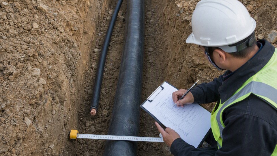
Small residential jobs are usually decisions about approved cable type, burial depth, GFCI protection, conduit at risers, and permit inspection. Commercial buildings, factories, utilities, renewable energy projects, mining sites, farms with heavy equipment, ports, rail corridors, and infrastructure work need formal design input because the cable becomes part of a larger electrical and civil system. Load growth, fault level, soil temperature, trench congestion, vehicle loading, water movement, spare capacity, and repair access all change the correct cable choice.
Do not buy underground cable only by conductor size and price per meter. The cheaper option can disappear quickly once you account for failed inspection, swollen sheath, overheated conductors, damaged insulation during pulling, unavailable replacement drums, or a supplier that cannot reproduce the same construction six months later. For bulk procurement, verify environmental resistance, mechanical protection, certification, factory testing, packaging, drum length control, production capacity, and long-term supply reliability.
For project review or quotation, contact Jinda with the project voltage, load current, route length, burial method, soil and water conditions, required standards, conductor preference, target delivery destination, and any drawings or photos of the route. Jinda can support cable selection, manufacturing, technical communication, project quotation, and after-sales coordination for international supply programs through its integrated R&D, production, sales, technical support, and service system.
Confirm before trenching, test before backfill, document before energization, and source underground cable from a manufacturer capable of supporting the full project lifecycle.