A cable buried too shallow gets found by the wrong tool: a fence post auger, a skid-steer tooth, a landscape spade, or a trench repair crew working from a faded drawing. The operational hit is usually worse than the repair itself: nuisance trips, feeder outages, water in damaged insulation, emergency excavation, and a production or tenant shutdown that nobody budgeted for. The right burial depth starts with the wiring method, voltage, route exposure, soil and surface use, then gets locked down against the local code and authority having jurisdiction.
Most residential direct-burial branch circuits are commonly installed with about 24 inches of cover, while PVC conduit installations may be allowed around 18 inches in many NEC-style applications. Industrial medium-voltage routes often fall around 600 mm to 1,200 mm, but the governing code, utility standard, and site risk decide the actual depth.
The catch is that “depth” is not just a number on a trench detail. It changes with conduit type, cable construction, vehicular loading, future excavation risk, warning tape practice, thermal backfill, utility crossing rules, and whether the installer is measuring cover from finished grade or from yesterday’s rough cut.
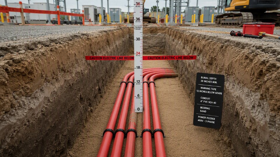
Depth rules by installation type
For planning, most private underground cable routes fall into a few familiar cover ranges: roughly 18 in. for many residential PVC conduit branch circuits, about 24 in. for common direct-buried residential feeders, and about 600 mm to 1,200 mm for higher-risk commercial, industrial, and medium-voltage work. These are not purchase-order specifications by themselves; the governing code, utility standard, cable listing, soil conditions, and approved drawings decide the final number.
| Installation type | Common planning cover range | What usually drives the final depth |
|---|---|---|
| Direct-buried residential branch circuit or feeder | About 24 in. | Cable listing, residential location, local electrical code, physical protection |
| Residential branch circuit in Schedule 40 PVC conduit | About 18 in. in many ordinary cases | Wiring method, circuit rating, GFCI rules where applicable, damage exposure |
| Rigid metal conduit or intermediate metal conduit | May be shallower in some code tables | Mechanical protection, corrosion risk, bonding and grounding continuity |
| Landscape, irrigation, communications, and control cable | Often shallower than power feeders when permitted | Extra-low-voltage classification, cable listing, mower/spade exposure, separation |
| Driveways, parking areas, roads, industrial yards | Often deeper or protected | Vehicle loading, paving, trench sharing, maintenance excavation, owner standards |
| Service laterals and utility-owned conductors | Utility-defined | Utility service manual, transformer location, meter rules, inspection process |
| Commercial and industrial low-voltage feeders | Commonly about 600 mm to 900 mm | Project specification, traffic risk, duct bank design, future expansion |
| Medium-voltage and high-voltage systems | Commonly about 750 mm to 1,200 mm or more | Fault energy, route criticality, warning systems, thermal design, utility practice |
Direct-buried residential branch circuits
About 24 in. of cover is a common benchmark for direct-buried residential underground feeder cable and similar branch-circuit applications because the earth itself is being relied on as part of the mechanical protection system. The cable jacket must be listed for direct burial, and the installation still needs the right transitions, protection where it emerges from grade, and approval by the local authority.
The practical reason for that extra depth is simple: direct-buried cable has no raceway wall to take the first hit from a shovel, edging tool, fence post auger, or later landscaping work. A homeowner may know where the trench is in year one; the next owner probably will not. At 24 in., the cable is below most casual digging, lawn aeration, and shallow irrigation work, though not below every post hole or mini-excavator bucket.
The weak points are usually not in the straight trench. They are at:
- Riser locations near a wall, pole, pedestal, or outbuilding.
- Sweeps where the installer fought the cable into a tight bend.
- Backfilled trenches containing brick, broken concrete, or sharp rock.
- Routes that cross future deck footings, gate posts, or drainage work.
- Splices made in boxes that later become buried or covered by mulch.
Direct burial can be economical because it avoids long conduit runs, elbows, and pulling labor. The trade-off is future serviceability. If the cable fails or the route changes, the repair often means excavation rather than pulling a new conductor through an existing raceway.
A 24 in. cover depth is a common planning benchmark for many direct-buried residential feeder-style installations, but it is not a universal rule.True
Depth depends on the adopted electrical code, cable type, circuit conditions, physical protection, and the authority having jurisdiction. Some installations qualify for different cover depths, while others require more protection.
Residential circuits in nonmetallic conduit
Around 18 in. of cover is a common planning figure for many ordinary residential branch circuits installed in Schedule 40 PVC conduit. The conduit gives the conductors a replaceable raceway and a degree of mechanical protection, but it does not make the route immune to impact, crushing, bad backfill, or poor installation workmanship.
Schedule 40 PVC is popular for residential underground work because it is affordable, corrosion-resistant, easy to cut, and forgiving for long yard runs. In practice, it also reduces buyer regret: if a cable is undersized, damaged during pulling, or later needs replacement, a correctly sized conduit gives the electrician a fighting chance without reopening the whole trench.
Depth still matters because PVC conduit is not structural pipe. It can deform under compacted rock, a narrow tire load, or a careless backhoe tooth. The usual field details matter more than they look on paper:
- Use long-radius sweeps where cable pulling tension could become high.
- Avoid too many bends between pull points.
- Keep glue joints clean and fully seated; half-glued PVC joints separate when the trench settles.
- Bed the conduit in sand or screened soil if the native material contains sharp stone.
- Protect risers above grade with a suitable method, often Schedule 80 PVC or metal where damage is likely.
Schedule 80 PVC is not just “better PVC”; it has a thicker wall and smaller internal diameter for the same nominal size. That helps where the raceway is exposed to physical damage, such as along a garage wall, behind a service pedestal, or where landscaping crews work. The sacrifice is harder pulling, especially with larger conductors or long runs. If the design is already tight on conduit fill or pulling tension, stepping up the conduit trade size may be the clean fix.
Rigid metal conduit and intermediate metal conduit
Rigid metal conduit and intermediate metal conduit may qualify for shallower burial in some electrical codes because they provide better mechanical protection than PVC or a bare direct-burial cable. That benefit only holds when corrosion protection, threaded joints, bonding, and grounding continuity are maintained through the entire underground and aboveground path.
Steel raceway handles shovel strikes and localized abuse better than PVC. It also provides an equipment grounding path where permitted and correctly installed, which can be useful in industrial yards with a lot of metallic equipment. But buried steel has its own failure mechanism: coating damage, wet soil, salts, fertilizers, stray current, and dissimilar-metal contact can turn a strong raceway into a corrosion job.
A few checks are worth making before choosing metal raceway just to gain a shallower trench:
- Is the soil corrosive, wet, coastal, chemically contaminated, or treated with deicing salt?
- Are factory-coated elbows or field-applied corrosion protection required?
- Will threaded couplings remain electrically continuous after years underground?
- Is an equipment grounding conductor still specified inside the raceway?
- Can maintenance staff distinguish the raceway from water, gas, or compressed-air lines during future excavation?
Metal raceway is often the right answer where exposed damage is the dominant risk. It is less attractive where corrosion, long pulling distances, or material cost dominate the job.
Low-voltage landscape, irrigation control, communications, and control cables
Extra-low-voltage systems are not the same as power feeders, and their burial rules are often less severe only because the shock and fault-energy risk is lower. Shallow burial may be allowed for listed landscape lighting cable, irrigation control wiring, communications cable, or instrumentation/control cable, but only when the cable type and installation method match the use.
This is an area where sloppy language causes trouble. “Low voltage” may mean 12 V landscape lighting to a landscaper, 24 VDC controls to an automation technician, 120 V branch circuits to a utility worker in some contexts, or under 1,000 V in industrial standards. Those are not interchangeable.
For shallow systems, the main risks are not usually arc-flash energy; they are nuisance failures and hidden damage:
- Lawn edging cuts jacket insulation near borders.
- Aerators punch control cable in spring maintenance.
- Rodents chew soft jacket materials in mulch beds.
- Irrigation repairs expose and nick wiring.
- Poor separation from power wiring creates interference or code problems.
For technical buyers, the buying point is listing and jacket construction, not just conductor size. A cheap indoor communications cable buried under wet soil may work for a season and then become a troubleshooting nuisance every time the ground freezes or the irrigation system runs.
Under driveways, parking areas, roads, and industrial yards
Under traffic areas, depth is no longer just an electrical-code number; it becomes a civil, maintenance, and asset-protection decision. Vehicle loading, paving section thickness, future excavation, and utility-corridor rules can increase cover or require duct banks, concrete encasement, warning tape, tracer wire, detectable marking, or spare conduits.
The mechanism is partly mechanical and partly organizational. A passenger-car driveway imposes a different risk than a forklift aisle, truck apron, container yard, or plant road used by vacuum trucks and mobile cranes. Paving also changes the repair economics. Cutting and restoring asphalt or reinforced concrete can cost more than the cable, especially if production access is blocked.
Industrial sites commonly add protection layers because the route will be forgotten by someone eventually. Useful protective measures include:
- Warning tape placed above the raceway at a shallower warning depth.
- Detectable tape or tracer wire for nonmetallic conduit routes.
- Concrete encasement where heavy traffic or congested corridors justify it.
- Red or electrical-colored concrete cap where accepted by the owner’s standard.
- Spare ducts for future feeders, controls, fiber, or temporary power.
- Accurate as-built drawings with offsets from fixed structures, not just “near fence.”
Concrete encasement improves protection and route definition, but it reduces flexibility. If the duct bank was undersized or placed in the wrong corridor, the plant inherits an expensive mistake. I would rather see one properly sized spare conduit installed during the first trench than a beautifully encased duct bank with no expansion path.
Service laterals and utility-owned conductors
Service laterals are often controlled by the serving utility or distribution company, not just the private electrical contractor. The utility may specify minimum cover, conduit size, sweep radius, trench inspection, bedding, separation from other utilities, meter location, and who is allowed to install or pull the conductors.
This is where procurement teams get caught. A contractor may price the job based on a familiar code-table depth, while the utility service guide requires a different trench detail or inspection before backfill. If the trench gets covered too early, the owner may pay to reopen it.
Before releasing materials or excavation, confirm:
- Whether the conductors are customer-owned or utility-owned.
- The exact service manual or utility drawing revision.
- Required conduit material and diameter.
- Minimum bending radius and sweep type.
- Transformer, handhole, pedestal, and meter clearances.
- Inspection hold points before backfill.
- Required warning tape, sand bedding, or marker posts.
The utility requirement wins at the service interface. Treat it as a supplier specification with inspection authority, because that is effectively what it is.
Commercial and industrial low-voltage feeders
For commercial and industrial low-voltage feeders, engineered burial depths around 600 mm to 900 mm are common planning territory where site risk is higher than a simple residential yard. Final values are normally set by the project specification, local jurisdiction, owner standards, traffic exposure, cable voltage class, and whether the feeders are in conduit, direct-buried, or installed in a duct bank.
Factories add complications that homes do not have. A feeder may cross steam condensate lines, oily wastewater trenches, compressed-air headers, fire mains, rail spurs, or pits that maintenance opens every shutdown. Forklifts chew up slab edges. Contractors add bollards later without checking as-builts. A burial depth that looks conservative on the electrical drawing can become marginal once civil works and maintenance habits are included.
For plant work, I like to review burial depth together with:
- Route criticality: Does one feeder stop a packaging line, furnace, pump station, or whole building?
- Access for repair: Can the trench be reopened without shutting a road, dock, or process area?
- Soil and drainage: Will the route sit in water after rain or snowmelt?
- Thermal loading: Are multiple loaded conduits grouped together?
- Expansion: Is there space for future ducts before the corridor is paved?
- Identification: Can the route be found in five years by a new maintenance crew?
The best depth is not the deepest trench; it is the depth that gives acceptable protection, heat performance, access, and code compliance for that route.
Medium-voltage and high-voltage cable systems
Medium-voltage and high-voltage underground systems often land in the 750 mm to 1,200 mm-plus range in substations, manufacturing plants, renewable energy projects, campuses, and utility corridors. The higher depth is driven by fault energy, public and worker exposure, route importance, utility practice, and the need for robust warning and protection systems.
At these voltages, the installation is a cable system, not just a cable in dirt. The design may include shield bonding, concentric neutrals, jacket testing, sheath voltage limiters, link boxes, grounding electrodes, thermal backfill, concrete duct banks, manholes, and route markers. Burial depth interacts with all of that.
The thermal issue deserves respect. A loaded power cable rejects heat through its insulation, jacket, duct or soil interface, surrounding soil, and finally to the ambient environment. If the cable is buried deeper, the heat path to the surface can become less favorable, especially in dry soil or in a congested duct bank with neighboring loaded circuits. That can reduce ampacity unless the design accounts for soil thermal resistivity, load factor, duct spacing, and seasonal moisture.
The protection trade-off can flip by project type:
- In a utility corridor with excavation risk, deeper burial and concrete protection may be justified.
- In a solar or wind farm with long collection circuits, excessive depth can inflate trenching cost and complicate thermal performance.
- In a substation, controlled access may allow a different balance of concrete trench, duct bank, and marked routes.
- In a chemical plant, corrosion, drainage, and emergency repair access may matter as much as nominal depth.
For medium-voltage procurement, do not buy cable solely from a burial-depth assumption. Confirm voltage class, insulation level, shield design, jacket type, water-blocking requirements, pulling tension, sidewall pressure, bend radius, and the installation environment before locking the cable construction.
Temporary power, construction sites, and event power
Temporary does not mean casual. For construction and event power, shallow burial can be more dangerous than a properly managed surface route because people keep moving fencing, ramps, tents, forklifts, scissor lifts, and trench plates after the electrical crew leaves.
Often the safer and more compliant choice is one of these methods:
- Surface-rated cable routed away from traffic and protected from pinch points.
- Cable ramps rated for the expected pedestrian or vehicle load.
- Overhead temporary drops with proper clearance and strain relief.
- Barriers, cones, and signage around generator and distribution areas.
- Short protected underground crossings installed to the applicable temporary-power rules.
- Daily inspection of connectors, jackets, ramps, and wet locations.
Temporary cable failures are usually caused by abrasion, crushed connectors, standing water, improvised splices, or someone “just moving it for a minute.” Burial only solves some of those problems. If the site layout changes every few days, visible and protected routing may beat a shallow trench that nobody can see.
Why deeper is not automatically safer
Excessive burial can create new problems: poorer heat dissipation, harder fault locating, higher excavation cost, longer outage duration, more difficult pulling geometry, and greater exposure to groundwater. Past a certain point, depth stops being cheap insurance and starts becoming a design penalty.
The thermal mechanism is the one many non-electrical buyers miss. Cable ampacity assumes heat can leave the conductor. Put the same loaded feeder deeper, group it with other hot circuits, surround it with dry native clay or poorly compacted fill, and the conductor temperature can rise even though the cable is “better protected” from a shovel. That heat ages insulation over time; it does not need to fail on day one to be a bad design.
Pulling and maintenance also get worse with unnecessary depth. Deeper trenches need more shoring or benching, more spoil handling, more dewatering, and more restoration. Long vertical risers and deep duct banks can increase pulling tension and sidewall pressure at bends. When a fault occurs, the repair crew faces a larger excavation, more permits, and a longer production outage.
The boundary is clear enough: if the governing code, utility, owner standard, or hazard analysis requires more cover or concrete protection, follow it. Where the designer has discretion, set burial depth with the whole installation in view — cable rating, route risk, soil, traffic, drainage, repair access, locating method, and the plant’s tolerance for downtime.
Codes and authority checks
The legally enforceable burial depth is the depth accepted by the authority having jurisdiction, not the number copied from a catalog, forum, or past job. Use code tables as the starting point, then confirm the edition, local amendments, wiring method, voltage class, route conditions, permit notes, and inspection requirements before trenching.
In the United States, the authority having jurisdiction is usually the electrical inspector, building department, utility, state agency, federal facility engineer, or a combination of them. On private industrial sites, the owner’s engineering standard may be stricter than the public code, especially where production downtime, fire exposure, or repair access carries high cost. I have seen projects where the trench was technically deep enough for a general code table, but failed inspection because the permit drawing called for warning tape, sand bedding, minimum separation from gas, or a different conduit material under a driveway.
NEC Table 300.5 is the common U.S. reference for minimum cover over buried wiring and raceways. It is useful, but it is not a universal burial-depth table. The required cover can change with:
- Wiring method, such as direct-burial cable, rigid metal conduit, intermediate metal conduit, PVC conduit, or residential branch-circuit cable.
- Circuit type and rating, including residential branch circuits, service laterals, low-voltage circuits, and higher-voltage feeders.
- Location conditions, such as under a driveway, parking area, building slab, landscape bed, or public road.
- Protection method, including GFCI protection, raceway type, concrete encasement, and physical damage protection.
- Code edition and local amendments adopted by the city, state, county, or project owner.
- Exceptions and notes in the table, which are easy to miss when someone only screenshots the main row.
NEC Table 300.5 can be used by itself to determine the final legal burial depth for any U.S. cable installation.False
NEC Table 300.5 is an important reference, but the final requirement depends on adopted code edition, local amendments, wiring method, circuit conditions, permit drawings, site conditions, and acceptance by the authority having jurisdiction.
Outside the United States, the control points are different. IEC-based projects often rely on national wiring rules, utility installation manuals, civil works specifications, and owner engineering standards rather than one single burial-depth table. A solar farm in the Middle East, a port expansion in Southeast Asia, and a mine feeder in Australia may all use XLPE power cable, but their trench details can differ because of soil thermal resistivity, mechanical protection expectations, road-crossing rules, public-utility separation, and the owner’s reliability philosophy.
For international procurement, the buyer should not ask only, “What depth is this cable rated for?” Cable is not normally “rated” for one burial depth in isolation. The cable datasheet gives construction details such as conductor size, insulation type, sheath, armor, voltage rating, and sometimes direct-burial suitability. The installation standard decides how that cable is installed: bedding, cover, duct bank design, thermal backfill, warning tape, route markers, pulling tension limits, bending radius, bonding, and test requirements.
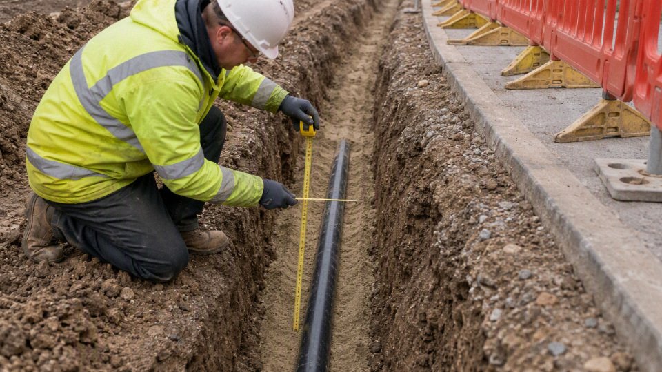
Burial depth is only one compliance item. A trench can pass the tape measure and still be electrically wrong. Before releasing a purchase order or mobilizing a trenching crew, check at least these items:
- Conductor ampacity under the actual installation condition, including grouping, soil temperature, soil thermal resistivity, and duct fill.
- Insulation voltage rating and suitability for wet location, direct burial, sunlight exposure at risers, oil exposure, or chemical exposure.
- Raceway fill and pulling limits, especially where long sweeps, spare ducts, or multiple bends make a neat drawing difficult to pull in practice.
- Grounding and bonding method, including metallic conduit continuity, armor bonding, concentric neutral treatment, and ground-fault path.
- Separation from other utilities, including gas, water, sewer, steam, telecom, instrumentation, and cathodic protection systems.
- Voltage drop on long runs, common on farms, campuses, ports, and renewable energy sites.
- Short-circuit withstand and fault-clearing coordination, which matter more as available fault current and feeder size increase.
- Mechanical protection at risers, foundations, road crossings, equipment pads, and areas exposed to augers, fence posts, or future excavation.
The mechanism behind several of these checks is simple but often ignored: deeper burial changes heat dissipation, repair access, and excavation risk. A deeper cable may be better protected from casual digging and frost movement, but it can run warmer if placed in poor thermal soil or a crowded duct bank with no engineered backfill. A shallower installation is cheaper and easier to repair, but only when the code, physical protection, route risk, and owner acceptance allow it. The preferred depth is not always the deepest practical trench; it is the approved installation that satisfies electrical performance, mechanical protection, maintainability, and inspection acceptance together.
Engineered design is needed when the consequences of guessing are high. Treat the following as design-engineer territory, not rule-of-thumb work:
- Medium-voltage feeders and distribution circuits.
- Hazardous classified areas with flammable gas, vapor, dust, or fibers.
- Chemical plants, refineries, tank farms, and wastewater facilities.
- Mines, tunnels, quarries, and heavy mobile-equipment routes.
- Renewable energy farms with long collection circuits and variable soil conditions.
- Airports, rail systems, ports, highways, bridges, and public infrastructure crossings.
- Data centers, hospitals, semiconductor plants, and other high-continuity facilities.
- Any route crossing a utility easement, public road, rail corridor, drainage channel, or property ownership boundary.
Before trenching, collect the project documents in one place. A foreman with a tape measure and a backhoe cannot resolve a code conflict from the bottom of an open trench.
- Approved IFC or construction drawings showing route, depth, wiring method, and crossing details.
- Cable datasheet and, where applicable, manufacturer installation guidance.
- Applicable installation standard, such as the adopted electrical code, utility manual, owner specification, or national wiring regulation.
- Excavation permit, electrical permit, road-opening permit, or right-of-way approval.
- Utility-locate record with ticket number, date, marked services, and any private-locate notes.
- Inspection checklist or hold-point plan, including bedding, depth, warning tape, conduit inspection, and backfill stages.
- As-built route plan requirements, including offsets, GPS records, marker posts, spare ducts, and photo records before backfill.
Do not copy a burial depth from the last project unless the conditions truly match. Soil, pavement, voltage, code edition, ownership boundary, cable construction, and public-access risk can all change the answer. A 600 mm trench that made sense inside a fenced industrial yard may be unacceptable under a municipal road, and an 18 inch residential conduit detail may be irrelevant for a medium-voltage feeder serving a process line. The safe commercial habit is to confirm the governing documents early, before cable is ordered and before civil work locks the project into an expensive rework path.
Cable and conduit choices
Cable burial depth is not just a trench dimension; it is tied to the cable construction and the wiring method approved for the job. A cable that is safe in duct may be wrong for direct soil contact, and a cable that survives soil contact may still need conduit where it rises at a pole, wall, pad-mounted cabinet, or driveway crossing. Select the cable system first, then confirm the cover depth against the governing code and site risk.
Direct-burial cable
Direct-burial cable must be specifically listed, specified, or designed for underground exposure at the applicable voltage class. That means the insulation, jacket, shielding, moisture blocking, and mechanical protection are selected for wet soil, cyclic loading, chemical exposure, and installation damage—not just for electrical performance in free air.
For residential and light commercial feeders, underground feeder and branch-circuit cable is commonly used for runs such as:
- House-to-garage feeders
- Yard lighting and small outbuilding circuits
- Pump circuits
- Gate operators and site equipment
- Low-voltage branch circuits where the local code permits the method
The weak points are rarely in the middle of the trench. They are usually at the transitions:
- Where the cable emerges from grade
- Where it enters a panel, meter base, junction box, or post
- Where landscaping crews, rodents, or sunlight can attack the exposed portion
- Where a bend is forced too tight because somebody did not leave enough trench width
- Where water tracks into a termination because the gland or seal was treated as an afterthought
In practice, I do not like leaving any direct-burial cable “naked” near grade, even if the buried portion is compliant. A short riser in rigid PVC, rigid metal conduit, or another approved protective sleeve is cheap compared with digging up a failed feeder after a skid steer clips it.
XLPE and EPR insulated power cables
For industrial low-voltage and medium-voltage underground systems, XLPE and EPR insulated power cables are common because they handle electrical stress, heat, and moisture better than many older general-purpose insulation systems. XLPE is widely used where dimensional stability, dielectric strength, and thermal rating matter. EPR is often favored where flexibility, wet aging performance, or handling robustness is valuable, especially on routes with bends, pulling tension, or repeated maintenance disturbance.
The mechanism matters for ampacity and life. Insulation is not just a separator between conductor and shield; it is part of the heat path and part of the electrical stress system. If the conductor runs hot because of poor soil thermal resistivity, tight duct grouping, high harmonic load, or undersized conductor selection, the insulation ages faster. In medium-voltage cable, poor shielding, water treeing, and termination stress can turn a seemingly small design shortcut into a very expensive outage.
The preferred insulation can flip with the job. XLPE may be attractive for standard duct-bank feeders and long procurement programs. EPR may be the better field choice where flexibility and wet-location tolerance reduce installation risk. That conclusion stops holding when the utility standard, plant specification, fire-performance requirement, or certified cable construction dictates one system.
Armor, conduit, and raceway protection
Armor and conduit solve different problems. Armor travels with the cable and adds mechanical protection along the whole route. Conduit or duct protects the route, improves replacement options, and may change the required cover depending on the code table and installation method.
| Option | Where it is used | What it protects against | Practical trade-off |
|---|---|---|---|
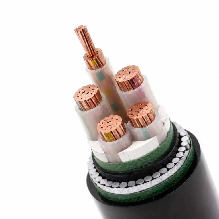
| Steel wire armor | Industrial direct burial, longer exposed-risk routes, utility-style feeders | Crush, pulling abuse, rodents, some excavation contact | Strong, but heavier and can increase pulling effort and handling cost |
| Steel tape armor | Buried power cable where radial protection is needed | Compression, impact, rodent attack | Good protection, but less flexible than unarmored cable |
| Aluminum armor | Corrosion-sensitive or weight-sensitive applications | Moderate mechanical damage, some shielding functions depending on design | Lighter than steel, but not a universal substitute for high-crush-risk routes |
| Other metallic protection or screens | Medium-voltage and special cable designs | Fault current path, shielding, moisture barrier, mechanical support depending on construction | Must be coordinated with grounding, bonding, and fault-duty requirements |
| PVC conduit | Residential, commercial, plant branch circuits, low-voltage feeders | Soil contact, minor mechanical protection, cable replacement path | Economical and corrosion-resistant, but needs correct burial cover, bedding, expansion allowance, and sweep radius |
| HDPE duct | Long pulls, directional boring, utility corridors | Soil contact and route continuity | Flexible and good for long underground runs, but terminations and transitions need discipline |
| Rigid metal conduit | Risers, exposed areas, traffic-prone locations, severe mechanical zones | Impact, crushing, physical abuse | Excellent protection, but corrosion protection and bonding cannot be ignored |
| Concrete-encased duct bank | Industrial plants, substations, dense feeder corridors | Route stability, traffic loading, multi-circuit organization | Durable and maintainable, but heat dissipation and installation cost become serious design variables |
| Cable trough or trench system | Plants, tunnels, substations, accessible corridors | Organized routing and inspection access | Easier maintenance, but drainage, covers, fire separation, and mechanical damage controls must be engineered |
Concrete encasement is a good example of the trade-off. It improves route protection and alignment, and it makes a plant electrical corridor easier to document. At the same time, grouped ducts in concrete can trap heat, especially if the soil around the bank is dry or poorly compacted. The electrical designer may need larger conductors, fewer loaded cables per duct, spare ducts, or a different feeder arrangement to hold ampacity.
Moisture barriers, jackets, and underground sheath design
Underground cable is assumed to get wet sooner or later. Even a well-installed duct bank can collect water through condensation, manholes, damaged joints, or grade changes. The jacket and moisture barrier should match the soil, water exposure, and fire environment.
Common choices include:
- Polyethylene jackets: good moisture resistance and toughness for many direct-burial and duct applications.
- PVC jackets: common and economical, with useful chemical resistance in many environments, though low-temperature handling and smoke behavior depend on formulation.
- Low-smoke zero-halogen compounds: used where smoke and corrosive gas reduction are required, often in tunnels, buildings, transit, or enclosed cable routes; they should not be specified casually for every buried job without checking mechanical and moisture requirements.
- Water-blocking tapes or powders: limit longitudinal water migration if the jacket is damaged.
- Metallic screens, tapes, or sheaths: provide shielding, fault current path, and in some designs a moisture barrier; grounding and bonding must match the system study.
- Lead sheath or special barrier constructions: still used in some severe wet, chemical, or utility applications, but they bring cost, handling, environmental, and termination considerations.
A cable installed underground should be treated as a wet-location product selection problem, even when it is pulled inside conduit.True
Underground raceways often accumulate water through condensation, leakage, or manhole flooding, so insulation, jacket, and termination choices must be suitable for wet service as required by the applicable standard and project specification.
Thermal implications of cable selection
Burial depth affects heat flow, but it is only one part of ampacity. Conductor size, copper or aluminum material, insulation temperature rating, number of loaded conductors, duct fill, spacing between circuits, soil thermal resistivity, ambient earth temperature, load profile, and backfill quality all interact.
A deeper installation may improve mechanical protection and reduce accidental strike risk, yet it can make heat rejection worse if the surrounding soil is dry, compacted poorly, or thermally resistive. A shallow installation may run cooler in some soils but be unacceptable for code cover or physical protection. This is why industrial medium-voltage feeders are not responsibly bought from a length-and-voltage description alone; the route and loading assumptions drive the cable design.
Procurement information Jinda should receive before quotation
For bulk cable procurement, the buyer should send enough information to define both the cable and the installation duty. At minimum, provide:
- Project voltage and system type, including AC or DC, phase arrangement, grounding method, and maximum operating voltage.
- Installation method: direct burial, PVC conduit, HDPE duct, rigid metal conduit, concrete-encased duct bank, tray, trough, tunnel, or mixed route.
- Governing standard or project specification, such as IEC, BS, VDE, ASTM, ICEA, NEC-style project requirements, utility specification, or owner standard.
- Conductor material, size, stranding class, number of cores, and neutral or grounding conductor requirements.
- Insulation type and voltage class, including XLPE, EPR, or other specified construction.
- Armor requirement: unarmored, steel wire armor, steel tape armor, aluminum armor, metallic sheath, screen, or project-specific mechanical protection.
- Sheath and jacket material, including polyethylene, PVC, low-smoke zero-halogen, oil-resistant, UV-resistant, termite-resistant, or other environmental requirements.
- Flame, smoke, halogen, or fire-performance requirements if the cable enters buildings, tunnels, substations, or enclosed industrial areas.
- Drum length, pulling length limits, maximum drum diameter or weight, and any container-loading restrictions.
- Required routine, type, sample, or witness tests, plus inspection documentation.
- Destination country documentation, marking language, packing requirements, certificates, and customs or project approval documents.
Jinda’s manufacturing scale and integrated technical support are most useful when the buyer defines the installation method early. If the depth, raceway, armor, and wet-location requirements are still undecided, the quotation can only be preliminary; the final cable construction should follow the approved route design and the authority having jurisdiction.
Site conditions that change depth
A burial depth that is legal on paper can still be poor engineering if the route crosses unstable ground, heavy traffic, aggressive soil, or areas likely to be excavated later. Treat the nominal minimum cover as the starting point; site conditions decide whether you add depth, conduit, bedding, concrete protection, route markers, or a different cable construction.
Finished grade and future grading
Required cover is measured from the final finished surface, not from the trench line on the day the crew installs the cable. That sounds obvious until a site contractor cuts 150 mm off a landscaped bank, a driveway gets resurfaced, or stormwater erosion exposes the warning tape after the first wet season.
For new industrial sites, I like to check the electrical route against the civil grading drawings, not just the electrical trench detail. Watch for:
- Planned asphalt or concrete paving thickness.
- Landscaping fill that may settle after compaction.
- Road shoulders that may be trimmed later.
- Drainage swales where water can wash away cover.
- Future building pads or equipment foundations that may change grade.
If the civil design is still moving, leave tolerance in the burial design. A cable installed at a perfect depth against an early drawing can become a shallow installation before the plant is even commissioned.
Vehicle and equipment loading
Driveways, forklift aisles, container yards, mine roads, farms, ports, and construction yards change the problem from “How much soil is above the cable?” to “What happens when a point load reaches the cable zone?” Shallow direct burial may be acceptable in a quiet lawn area and completely unsuitable under a loaded reach stacker lane or a farm track used by tractors with narrow tires.
The mechanism is simple: wheel loads spread through soil, but not evenly, and wet or poorly compacted soil transfers stress badly. If the cable is close to the surface, the bedding and jacket see more deformation, especially where stones, voids, or old rubble sit against the cable. In practice, the fix is not always just “dig deeper.” Options include:
- Rigid or heavy-wall conduit through traffic zones.
- Concrete-encased duct banks where routes cross plant roads.
- Protective slabs or cable tiles above the cable.
- Route relocation away from crane pads, haul roads, or laydown areas.
- Controlled backfill and compaction around the duct envelope.
The trade-off is access. More concrete and deeper duct improve mechanical survival, but repairs become slower, more expensive, and more disruptive. For critical feeders under a port apron or mine haul road, that is usually acceptable. For a lightly loaded service to a small pump house, a simpler protected crossing may be the cleaner design.
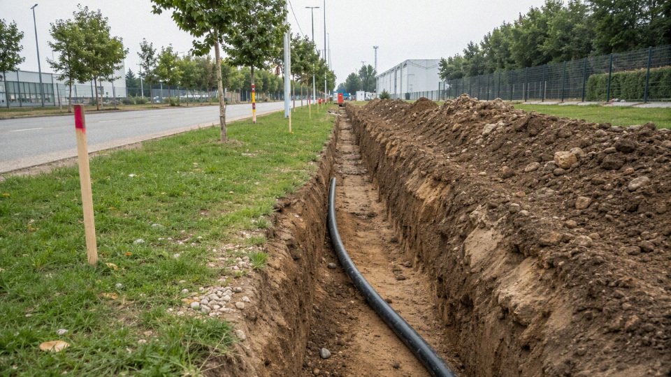
Rocky soil, sharp backfill, and unstable ground
Rocky trenches are cable killers. A direct-burial jacket can survive soil pressure, but sharp aggregate, broken concrete, slag, or careless backfill can cut or indent it during placement and compaction. Damage may not fail the cable on the megger test that day; it may show up months later after moisture gets into the jacket defect.
Use the trench detail to control contact surfaces:
- Place bedding sand or screened fine backfill under and around the cable.
- Remove sharp stone from the immediate cable zone.
- Use protective boards, tiles, or slabs where later hand digging is likely.
- Consider conduit or duct where the trench bottom cannot be cleaned properly.
- Avoid laying cable across unstable fill without settlement review.
Unstable ground adds another issue: movement. Settlement can pull on joints, bend ducts, or concentrate load at a transition point between soft soil and a rigid concrete structure. Pay special attention where the route enters buildings, pits, manholes, transformer pads, or retaining walls.
Wet soil, flood zones, and high water tables
Wet ground does not automatically require a deeper trench, but it does change cable construction and joint design. Medium-voltage polymeric insulation is sensitive to long-term moisture stress; water-treeing risk depends on insulation system, voltage stress, manufacturing quality, shielding, jacket condition, and service environment. Water-blocked cable designs, longitudinal barriers, suitable jackets, and properly sealed terminations become more important in high water table routes.
Flooded ducts bring their own problems:
- Ducts can float or shift before backfill if not restrained.
- Pull boxes and handholes can become permanent water sumps.
- Poorly sealed joints allow moisture migration along the conductor screen or armor.
- Metallic armor, screens, and glands may corrode if the soil water is aggressive.
- Freeze-thaw in water-filled voids can move poorly supported ducts.
For procurement, “suitable for direct burial” is not the same as “suitable for permanently wet, chemically aggressive, flood-prone service.” Ask for the cable design basis and installation accessories as a system, especially for medium-voltage and critical industrial feeders.
Chemical, oil, salt, and contaminated soil
Soil chemistry can make a standard burial detail age badly. Petrochemical sites, tank farms, ports, deicing areas, mines, battery rooms, wastewater facilities, and old industrial land may contain hydrocarbons, acids, alkalis, salts, solvents, or conductive contamination. The exposed part may not be the conductor; it is often the jacket, armor, concentric neutral, sheath, gland, or earth continuity component.
Possible responses include:
- Selecting a jacket compound compatible with the contaminant exposure.
- Adding corrosion protection for metallic armor or sheaths.
- Using non-metallic ducts where corrosion risk is severe.
- Rerouting away from known contaminated zones.
- Specifying sealed conduits, watertight joints, and compatible accessories.
This is one area where a soil report is worth more than a debate in a meeting room. Without knowing the contaminant type, concentration, moisture level, and exposure duration, any jacket recommendation is only a guess.
Rodent, termite, and biological attack
Rural feeders, solar farms, warehouses near fields, plantations, and warm damp regions can suffer from rodents, termites, insects, and root intrusion. The risk is not evenly distributed; it tends to concentrate near food sources, drains, embankments, waste areas, and quiet service corridors that nobody inspects.
Controls include:
- Metallic armor where allowed and suitable for the earthing system.
- Harder or more resistant jacket compounds where available.
- Conduit or duct in vulnerable zones.
- Route selection away from burrows, vegetation lines, and waste storage.
- Better sealing at handholes, cabinet bases, and building entries.
Armor adds mechanical protection, but it also adds cost, pulling weight, termination work, and corrosion considerations. The preferred choice flips when the route is long, low-risk, and easy to inspect; then a good duct route with accessible pulling points may be more practical than armoring every meter.
Thermal resistivity and cable ampacity
Deeper burial can reduce mechanical risk while making heat rejection worse. Cables lose heat through the surrounding soil. Dry sand, poorly compacted fill, concrete encasement, multiple loaded circuits, and deep installation can raise the thermal resistance around the cable, which increases conductor temperature for the same current.
That path matters commercially: higher operating temperature shortens insulation life and may force a larger conductor, different insulation rating, wider circuit spacing, or a lower allowable load. With medium-voltage industrial feeders, the ampacity calculation should reflect:
- Native soil thermal resistivity, ideally measured rather than assumed.
- Seasonal moisture changes; dry summer soil can be the limiting case.
- Number of circuits in the trench or duct bank.
- Cable spacing and arrangement.
- Duct material and concrete encasement.
- Load profile, not just nameplate current.
- Emergency overload expectations.
A deeper trench is not automatically a better trench if the feeder is thermally constrained. That conclusion stops holding where mechanical protection, utility rules, or third-party damage risk dominate the design; then you solve ampacity with conductor size, spacing, duct bank layout, or route changes.
Separation from other utilities
Cable depth cannot be designed in isolation from gas, water, steam, telecommunications, drainage, and cathodic protection systems. Minimum spacing is normally set by local utility rules, project specifications, and the authority having jurisdiction, so avoid copying a generic clearance from another region.
The practical reasons are clear enough:
- Gas lines need safe excavation clearance and may have strict crossing rules.
- Steam and hot water lines can overheat nearby cables.
- Water and drainage lines can leak, wash out bedding, or flood ducts.
- Telecommunications routes need separation from power for safety and serviceability.
- Cathodic protection systems can create corrosion and interference concerns.
- Shared corridors can become impossible to maintain if everything is stacked tightly.
Coordinate crossings early. A beautiful cable trench drawing becomes worthless when the civil crew discovers an unmarked drain or a gas utility refuses the proposed crossing angle.
Frost depth and seasonal movement
Frost depth is often misunderstood. Electrical cable burial depth is not normally determined by frost depth alone, but freezing ground can affect mechanical stability, duct movement, shallow handholes, and transitions into structures. In cold regions, seasonal heave can stress conduits, pull on terminations, or crack poorly supported encasement at rigid interfaces.
Design attention should go to the movement points: building entries, pole risers, transformer pads, handholes, road crossings, and areas with poor drainage. Good bedding, drainage control, expansion allowance where appropriate, and robust riser protection often matter more than chasing frost depth as a single number.
Future excavation risk
The cable that fails ten years later is often hit by a bucket, fence post auger, landscaping stake, drain repair crew, or contractor who never saw the original drawings. Depth helps, but identification is just as important.
Use several layers of defense:
- Warning tape above the cable at the specified height.
- Detectable tape or tracer where non-metallic ducts are used.
- Marker posts or route markers at direction changes and field crossings.
- Durable tags in handholes, cabinets, and building entries.
- As-built drawings corrected after installation, not before.
- Geographic coordinates for long outdoor routes.
- Photos before backfill, with fixed reference points.
- Maintenance records showing joint, splice, and crossing locations.
Good documentation is cheap compared with one damaged feeder under a paved yard. The burial design is not finished when the trench is backfilled; it is finished when the next maintenance crew can find the cable without guessing.
Trench construction essentials
- Lock down the work package before the excavator starts.
Verify the latest approved drawings, route coordinates, burial depth, cable schedule, conduit size, pull box locations, permits, and inspection hold points. On a good crew this sounds obvious; on a rushed job it is exactly where mistakes start. Utility locating must be completed and marked in the field, not just checked on a drawing. Confirm isolation requirements for nearby live services, traffic control, dewatering needs, spoil storage, trench access, and delivery timing for cable drums, ducts, warning tape, bedding, spacers, and protection slabs.Trench safety is not paperwork decoration. Shoring, benching, trench boxes, ladder access, gas testing where required, and exclusion zones around plant need to match soil conditions and local rules. A cable job can be technically perfect and still fail commercially if a stop-work order shuts the route for two days because trench protection was treated as optional.
- Excavate the trench wide enough for the installation method, not just the cable diameter.
Width has to allow placement, separation, bedding, compaction equipment, and pulling access without forcing workers to drag cable against the trench wall. For a single small conduit, the trench may be narrow. For multiple ducts, medium-voltage circuits, trefoil groups, or power and control segregation, a cramped trench quickly becomes a quality problem.The mechanism is simple: if the trench is too narrow, workers lose control of duct alignment and cable position. That leads to poor bedding under the duct, uneven cover, damaged jackets, tight bends, and inconsistent spacing. Wider excavation costs more in digging, reinstatement, and spoil handling, but the preferred choice flips when the route carries heat-sensitive power cables, multiple circuits, or inspection-critical work under a road crossing.
Prepare the trench bottom before placing duct or cable.
The bottom should be smooth, firm, and free of sharp stones, broken concrete, scrap metal, roots, and hard high spots. Where the specification calls for sand, selected soil, screened material, or thermal backfill, install it to the required thickness before the cable or conduit goes in. Do not use bedding as a way to hide a rough trench bottom; the cable will still find the point load after compaction and settlement.Duct banks need continuous support. Short unsupported spans under PVC or HDPE conduit can deform during backfill, especially if a plate compactor is used aggressively above shallow cover. Bell mouths, spacers, and sweep bends should be checked before burial, because a collapsed or misaligned duct is expensive to discover when the pulling crew arrives.
Handle cable as a manufactured product, not as rope.
Confirm the cable minimum bending radius, maximum pulling tension, sidewall pressure limits, pulling lubricant compatibility, installation temperature limits, and approved pulling method from the cable data and project specification. Drum orientation matters: pull from the correct direction so the cable pays off smoothly rather than corkscrewing across the ground. Use rollers, corner rollers, bell mouths, and temporary protection at trench edges.Jacket abrasion is one of those quiet defects that may not trip a test immediately but shortens service life. Keep cable off crushed stone, rebar, rough asphalt, and steel trench plates. In cold weather, many polymeric jackets become stiffer; the allowable bending and pulling behavior can change enough that a morning pull after a freezing night is not the same job as an afternoon pull in mild weather.
Maintain cable spacing, grouping, and identification while the trench is still open.
Spacing is not only for neatness. Power cables generate heat, and closely grouped loaded circuits can raise conductor temperature through mutual heating. That reduces ampacity margin and accelerates insulation aging if it was not included in the design calculation. Keep the specified arrangement for single-core phases, trefoil or flat formation, neutral and ground conductors, and spare ducts.Separate power, control, instrumentation, and communication cables as required by the design and local practice. The reasons include electromagnetic interference, fault energy exposure, maintenance access, and future identification. Use durable markers, tags, colored ducts, or route records before backfill hides everything. A tidy as-built photo with a tape measure in the frame is often worth more than a paragraph in a site diary.
Install warning tape and mechanical protection at the correct stage.
Warning tape belongs above the cable or duct at an intermediate depth where a future excavator or hand-digging crew will encounter it before striking the service. Do not place it directly on the cable; by then it is too late to warn anyone. The exact depth and tape type should follow the project specification or local utility requirement.Use mechanical protection where later excavation risk is credible, such as:
- Road crossings and parking areas.
- Shallow entries near buildings.
- Plant areas with frequent civil modifications.
- Shared utility corridors.
- Agricultural, mining, or industrial yards where deep ripping, augers, or post holes may occur.
Protection may be concrete slabs, polymer boards, bricks, tiles, steel plates, or encased duct, depending on the governing standard and site risk. Steel plate gives excellent strike resistance but can complicate corrosion, earthing, detection, and future excavation planning if it is used casually.
Backfill in controlled stages, not in one rough push.
First surround the cable or duct with approved fine material and compact carefully enough to remove voids without deforming conduit or damaging the sheath. Keep sharp debris, demolition waste, large stones, frozen lumps, and chemically aggressive fill away from the cable zone. After the protective layer is complete, general backfill can proceed in lifts suited to the surface finish and loading.Under paved areas, yards, rail approaches, and roads, compaction is a civil performance issue as much as an electrical one. Poor compaction causes settlement; settlement can crack pavement, expose conduits, reduce effective cover, and create water paths along the trench. Over-compaction directly above shallow duct can be just as bad, so equipment selection should match cover depth and duct strength.
Protect every transition above grade.
Cables emerging from soil need conduit, guards, sleeves, raceways, or other mechanical protection where they rise on poles, enter panels, pass through walls, or transition into equipment. These points see impact, UV exposure, rodents, water entry, thermal movement, and careless maintenance traffic. Seal wall penetrations and building entries as specified, but avoid trapping water in a way that turns the conduit into a drain toward the switchboard.Test before energization and before access is lost.
Minimum checks usually include continuity, phase identification, grounding and bonding verification, insulation resistance, and inspection of terminations. Where applicable, perform sheath integrity testing, duct proving, cable route verification, and conductor resistance checks. Medium-voltage installations normally require a formal commissioning plan, which may include VLF withstand testing, tan delta, partial discharge testing, sheath testing, phasing, and protection relay interface checks depending on the cable system and local acceptance practice.A cable installed at the correct nominal burial depth can still fail early if trench bedding, handling, spacing, protection, or backfill are poorly controlled.True
Burial depth controls cover, but cable life is also affected by mechanical damage, thermal environment, moisture paths, installation stress, and termination quality. These are established engineering considerations, though exact test requirements must come from the project specification, cable manufacturer, and local authority.
Do not backfill critical sections until required inspections, photographs, measurements, and test records are complete. Once the trench is closed, every uncertainty becomes slower and more expensive to resolve.
Industrial procurement evidence
For underground cable procurement, the purchase order should not stop at “burial-rated cable” or a quoted depth. Buyers need evidence that the cable construction, test record, packaging, and declared standard match the approved design and the route conditions. This matters even more in cross-border projects, where a cable that is acceptable under one standard may not be automatically acceptable under another.
A useful cable datasheet should state, at minimum:
- Voltage rating, including Uo/U or equivalent system designation, not just a marketing voltage class.
- Conductor material and class, such as copper or aluminum, stranded or compacted, with the applicable conductor standard.
- Insulation type, for example XLPE, EPR, PVC, or another specified compound, with temperature rating.
- Screen or shield construction, including metallic screen material, tape or wire arrangement, and short-circuit capacity where relevant.
- Armor design, if required, such as steel wire armor, aluminum wire armor, or tape armor, matched to mechanical risk and single-core/multicore behavior.
- Outer sheath material, including resistance needs for moisture, abrasion, UV exposure during storage, oils, chemicals, termites, or hydrocarbons where applicable.
- Fire performance, if the cable transitions into tunnels, substations, plants, or buildings where flame spread, smoke, or halogen limits are specified.
- Applicable standard, stated clearly as IEC, BS, VDE, AS/NZS, UL, ICEA, AEIC, or another project requirement.
Do not mix standards casually. An IEC medium-voltage cable, a UL-listed feeder cable, and an ICEA/AEIC utility cable may all be technically sound products, but their test methods, marking rules, conductor assumptions, and acceptance documentation are not identical. If the design basis says IEC, buy and inspect against IEC unless the engineer of record approves a formal equivalency. That approval should be written, not buried in an email chain after the cable has already shipped.
Factory documentation is where procurement separates a serious order from a risky commodity buy. Ask for:
- Type test reports for the relevant cable family and standard.
- Routine test reports for the actual production batch.
- High-voltage test results.
- Conductor resistance records.
- Dimensional checks for insulation, screen, armor, and sheath.
- Material traceability for conductor, insulation compound, sheath compound, armor, and drums.
- Inspection and release records, preferably tied to drum numbers.
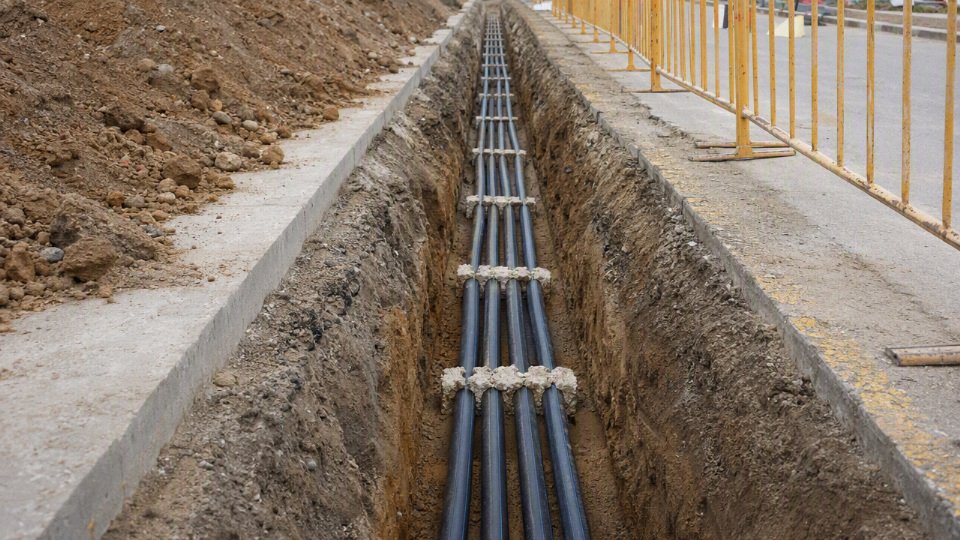
Packaging and logistics deserve the same discipline. Confirm drum size against unloading equipment, transport route limits, storage space, and pulling plan. A cable that is technically correct can still become scrap if the drum is too large for the site crane, the flange is damaged in transit, the ends are not sealed, or the minimum bending radius is violated during handling. Specify cable length tolerance, drum length schedule, end sealing, storage conditions, lifting points, and whether the cable will sit through a wet season before installation.
Supplier capability is not only about price and delivery date. For industrial and utility underground work, look for manufacturing scale, engineering support, customization capability, export documentation, after-sales response, and experience supplying similar voltage classes and installation environments.
Shandong Jinda Special Cable Group Co., Ltd. was established in 1987 and supports global cable projects through integrated research and development, production, sales, technical support, and after-sales service.True
This matches the supplied company profile and is presented as company positioning, not as a substitute for project-specific compliance verification.
For buyers comparing international cable suppliers, that integrated support can be valuable when the order includes non-standard sheath requirements, project-specific inspection documents, export packing, or multiple drum lengths for staged installation. The final approval still belongs to the project specification, the governing standard, and the authority or owner accepting the installation.
Inspection and maintenance risks
Most buried cable failures are not caused by the burial depth number alone; they come from a weak installation detail that stays invisible until load, moisture, movement, or excavation exposes it. The cheapest risk control is inspection before backfill, because after the trench is closed every defect becomes harder to prove, locate, and repair without outage time.
Common installation defects worth catching while the trench is open include:
- Insufficient cover: often caused by trench high spots, poor grade control, or later site regrading. A cable that left the crew at the right depth can end up shallow after landscaping, paving, or drainage work.
- Wrong cable type: indoor-rated cable, non-direct-burial insulation, or unsuitable jacket material may look acceptable on a reel but fail early in wet soil or duct water.
- Damaged jacket: cuts from pulling, reel handling, sharp conduit edges, or careless knife work at terminations give moisture a starting point.
- Sharp backfill: broken concrete, slag, rock, or scrap metal in the trench can point-load the sheath as the ground settles.
- Poor compaction: loose fill settles unevenly, leaving ducts unsupported or pulling stress into elbows, risers, and handholes.
- Missing warning tape or marker tape: future excavators lose the early warning layer and may hit the cable before anyone realizes they are in the danger zone.
- Unprotected risers: the transition from buried run to wall, pole, tray, or equipment pad is a favorite damage point from forklifts, weed trimmers, UV exposure, and casual maintenance work.
Electrical failure normally follows a chain. A small jacket defect admits moisture; moisture migrates along shields, strands, or fillers; insulation resistance drops; heat and electrical stress accelerate aging. In medium-voltage systems, voids, contaminated terminations, poor stress control, or wet insulation can lead to partial discharge, which erodes insulation locally rather than failing the whole feeder at once. Low-voltage circuits are less often discussed this way, but they still suffer from overheating when derating was missed for grouped conduits, high soil thermal resistivity, solar-heated pavement above the route, or load growth after new equipment is added. Termination failure is another regular culprit: loose lugs, poor crimping, wrong gland selection, missing sealing kits, and bad workmanship in a crowded cabinet.
Mechanical failures are just as common and usually less polite. The main ones are:
- Crushing from heavy traffic, poor duct encasement, or shallow crossing points.
- Excavation strikes from trenchers, augers, fence posts, grounding rods, or drainage repairs.
- Rodent damage, especially where cable exits ducts into handholes or poorly sealed pits.
- Settlement at road crossings, building entries, and transitions between compacted and soft ground.
- Duct collapse from inadequate stiffness, thermal deformation, bad bedding, or overload during construction.
- Excessive pulling tension that stretches conductors, opens shields, or damages insulation during installation.
- Bending-radius violation at elbows, risers, vault entries, and tight equipment pads.
Corrosion and environmental degradation deserve their own check, especially on industrial sites. Metallic armor, screens, and sheaths can corrode in aggressive soils or where stray currents are present. Polymeric jackets may crack from UV exposure at risers, chemical contact, incompatible oils, solvents, landfill gases, salt spray near coastal sites, or soil chemistry outside the cable maker’s assumptions. If the route crosses a chemical loading bay, battery area, wastewater plant, desalination facility, or salted road, do not treat it like a clean residential lawn.
Before backfill is complete, the inspection should verify:
- Cover depth at representative points, crossings, risers, and any route change.
- Route position against drawings, offsets, coordinates, and fixed landmarks.
- Bedding material, side support, and absence of sharp debris.
- Duct condition, mandrel results where required, joint integrity, slope, and drainage risk.
- Cable identification, phase marking, voltage class, and installed drum records.
- Separation distances from water, gas, communications, steam, fuel, foundations, and other power circuits.
- Test results required by the project, such as continuity, insulation resistance, sheath integrity, or medium-voltage commissioning tests.
- As-built records, including photos before cover, depth notes, splice locations, warning tape position, and marker locations.
Maintenance planning is mostly about preventing people from unknowingly creating the next fault. Keep route maps controlled, not buried in one engineer’s laptop. Install durable surface markers where the site permits them, tie excavation permits to electrical route review, and make underground cable checks part of management-of-change when loads are added. Critical feeders should be retested according to the site reliability policy and the cable type; the interval is not universal, because duty cycle, voltage class, environment, and outage consequence change the economics.
Repair makes sense for an isolated strike, a clean termination problem, or a known local jacket defect. Replacement starts to look better when faults repeat, moisture ingress is widespread, the insulation system is obsolete, ampacity is no longer adequate, or the route is so congested that every repair creates a new excavation hazard. Once the unknown section of buried cable becomes the plant’s recurring outage source, the financial decision often shifts from “fix the fault” to “remove the uncertainty.”
Frequently asked questions
How deep should a residential underground electrical cable be buried?
For early planning, many residential underground branch-circuit installations fall around 18 to 24 inches of cover, depending on whether the cable is in an approved raceway or is a direct-burial wiring method. A common NEC-style benchmark is roughly 24 inches for many direct-burial residential branch circuits, while some PVC conduit residential branch-circuit cases are often planned around 18 inches.
Do not buy cable, rent a trencher, or pour a driveway based only on those numbers. The permit set, local amendments, utility rules, GFCI protection, circuit voltage, wiring method, and the authority having jurisdiction can all change the allowed cover.
Is 12 inches deep enough for electrical cable?
Sometimes, but it is not a general burial-depth rule. Shallow cover is usually limited to specific protected installations, such as certain low-voltage landscape circuits, circuits under special protection, or wiring in approved rigid metal raceway where the code table and local inspector allow it.
The practical risk is that 12 inches is within the “normal damage zone” of many sites. Fence posts, irrigation repairs, edging stakes, root removal, and a tired maintenance crew with a pick can all reach that depth. If the design relies on shallow cover, the protection method and marking need to be intentional, not an afterthought.
Can I bury ordinary indoor cable underground?
No. Ordinary indoor cable is not suitable for direct burial unless its listing specifically allows the underground installation method being used. Indoor cable jackets are not designed for long-term soil moisture, chemical exposure, compaction, abrasion, or water migration inside conduit.
If cable is installed in underground conduit, that still does not automatically make an indoor-only cable acceptable. Many underground conduits are treated as wet locations because water eventually gets in through condensation, damaged joints, or grade movement. Use cable or conductors rated for the actual environment and installed according to their listing.
Does conduit reduce the required burial depth?
It can, in some code tables, but only when the raceway type, circuit type, location, and authority requirements match the table condition. PVC conduit, rigid metal conduit, intermediate metal conduit, direct-burial cable, and concrete-encased duct are not treated the same.
The trade-off is simple on paper and messier in the trench: conduit may allow less cover in certain cases and improves replaceability, but it adds fittings, sweeps, pulling tension limits, water management issues, and procurement cost. A cheap thin-wall substitution because “it is only underground for ten meters” is exactly the kind of field change that gets rejected at inspection.
How deep should cable be under a driveway?
A driveway route usually needs more conservative design than a lawn route because the cable system sees vehicle loading, sub-base compaction, future saw-cutting, drainage changes, and repair work. The required cover may increase, or the design may need stronger conduit, a duct bank, sleeves, or other mechanical protection.
For light residential driveways, the governing code and local inspector still set the minimum. For commercial yards, loading docks, forklift aisles, truck gates, and plant roads, the civil load case matters as much as the electrical table. In practice, I would rather pay for a proper sleeve before paving than argue later about a failed feeder trapped under reinforced concrete.
Do underground cables need warning tape?
Warning tape or detectable marking is strongly recommended and is often required for utility, commercial, and industrial underground routes. It gives the next excavator a chance to stop before reaching the cable or conduit.
For plant work, use marking that matches the site’s excavation procedure, not just whatever roll is sitting in the stores cage. Typical choices include:
- Non-detectable warning tape above shallow or known routes.
- Detectable tape or tracer wire for nonmetallic conduit or long buried runs.
- Surface markers, route posts, or as-built coordinates for medium-voltage and utility feeders.
- Color and wording consistent with local utility and site standards.
Can power and data cables share the same trench?
Shared trenches may be possible, but only with the required separation, shielding, raceway rules, and coordination between the electrical designer, telecom provider, utility owner, and inspector. Power cable can create induced noise, fault-energy hazards, and maintenance conflicts for data or control circuits.
The acceptable arrangement depends on voltage, cable construction, raceway material, grounding, communication cable rating, and whether the trench is private plant infrastructure or utility-owned. Do not let the civil contractor decide this in the field because “the trench is already open.”
Should medium-voltage cable be direct buried or installed in duct?
Medium-voltage cable can be direct buried, installed in ducts, or placed in concrete-encased duct banks, but the right choice depends on repair strategy, route risk, thermal design, and the owner’s standard. Typical industrial medium-voltage cover is often in the broad range of about 600 mm to 1,200 mm, but voltage class, soil conditions, utility practice, and mechanical exposure control the final design.
Direct burial can have favorable heat dissipation when the soil is suitable and the route is protected, but repairs are excavation-heavy and fault location can be painful. Duct systems improve replaceability and route organization, though ampacity may be lower if heat cannot leave the duct bank efficiently. Concrete-encased duct banks provide strong mechanical protection and a disciplined layout, but they cost more, require careful civil work, and need engineered thermal calculations for heavily loaded feeders.
What is the difference between burial depth and cable ampacity?
Burial depth is the amount of cover above the cable or raceway. Ampacity is the current the conductor can carry without exceeding its insulation temperature limit under the installed conditions.
Depth affects ampacity because deeper soil may have different temperature and moisture behavior, and heat has a longer path to ambient. But depth alone does not prove the conductor is large enough. Ampacity depends on conductor size and material, insulation rating, soil thermal resistivity, load factor, grouping, duct configuration, ambient temperature, and installation method.
A cable buried at the correct code depth is automatically sized correctly for the load.False
Burial depth is only one installation condition. Conductor ampacity still has to be calculated or verified using the applicable code method, cable data, grouping, soil thermal conditions, and load profile.
Who approves the final burial depth?
The final burial depth must be approved by the authority having jurisdiction, utility owner, project engineer, or industrial site owner responsible for the installation. On many projects, more than one party has a say: the electrical inspector may enforce code, the utility may enforce service rules, and the plant owner may impose stricter internal standards.
Get that approval before trenching. Once cable is in the ground, changing cover means rework, schedule loss, and sometimes scrapping a route that looked perfectly fine on a generic depth chart.
Verify your burial specification
Treat burial depth as the last confirmed number, not the first buying assumption. The correct specification comes after the cable type, wiring method, voltage class, route location, mechanical exposure, soil behavior, thermal design, and governing authority are tied together in one approved installation detail.
Before issuing a purchase order or releasing a trench crew, verify the following items against the project drawings, local code, utility requirement, or approved engineering standard:
- Approved standard or authority basis
- NEC-style table, IEC-based project specification, utility standard, local electrical code, or owner engineering standard.
- Record who has approval authority: inspector, utility engineer, EPC designer, plant electrical owner, or mine/site safety department.
- Minimum cover and finished grade reference
- Confirm whether the stated depth is measured to the top of cable, top of conduit, top of duct bank, or bottom of trench.
- Check future grading, paving, floor slabs, drainage works, and road resurfacing. I have seen good trench work become non-compliant after a civil contractor “corrected” the grade.
- Trench and protection detail
- Bedding material, backfill compaction, concrete encasement if required, road-crossing protection, and bend radius control.
- If conduit is used, confirm duct size, pull length, sweep radius, lubricant compatibility, and spare duct requirements.
- Cable datasheet and installation rating
- Voltage rating, conductor material and size, insulation system, sheath or jacket material, water-blocking design, flame or fire performance where relevant, and rated installation environment.
- For direct burial, the datasheet must support that use. A cable intended for tray, indoor conduit, or dry locations is not made suitable just because it is buried deeper.
- Armor, conduit, or mechanical protection
- Choose this based on route risk: vehicle traffic, excavator exposure, rocky soil, rodent risk, plant maintenance access, and public crossing areas.
- The trade-off is familiar: conduit or armor improves mechanical protection and maintainability, but increases material cost, pulling complexity, heat retention, and sometimes trench width.
- Warning tape, marker posts, and route records
- Warning tape should be placed above the cable at the specified level, not casually thrown into the backfill pile.
- Keep as-built route drawings, GPS points where useful, joint locations, and crossing records for future maintenance crews.
- Separation distances
- Verify spacing from gas, water, communications, drainage, steam lines, grounding conductors, other power circuits, foundations, and lightning protection systems.
- Thermal grouping matters. Several loaded feeders in one trench can run hotter than the same cables installed separately.
- Testing plan and inspection hold points
- Typical checks include receiving inspection, sheath inspection, insulation resistance testing, continuity checks, phase identification, and any project-specified withstand or VLF testing for medium-voltage circuits.
- Hold points should cover trench depth before bedding, cable placement before backfill, warning tape placement, and final as-built documentation.
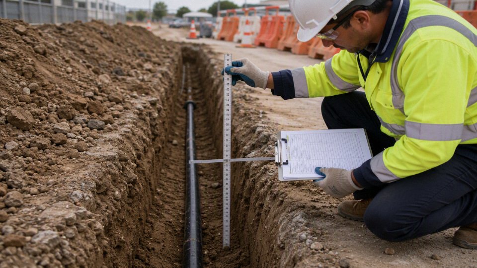
A trench can be the correct depth and still be the wrong installation if the cable construction does not match the burial method. Moisture ingress, sheath abrasion, poor pulling practice, excessive sidewall pressure, overloaded ampacity, or incompatible backfill can shorten service life without leaving an obvious defect at commissioning. That is why procurement should not separate “cable price” from “installation condition”; the cheaper cable often becomes expensive when it forces redesign, added protection, or early replacement.
For an underground power cable review, send the practical details before procurement: voltage rating, route length, installation environment, applicable standard, conductor size, expected load, preferred armor type if any, sheath or jacket requirement, burial method, soil or ambient temperature assumptions, and destination market. Clear route drawings, trench details, and any owner or utility specification help remove guesswork.
Shandong Jinda Special Cable Group Co., Ltd. can support underground power cable selection, specification review, bulk quotation, and project supply planning for international cable projects. With manufacturing, R&D, sales, technical support, and after-sales service integrated across its cable operations, Jinda’s team can help align the cable construction with the approved burial method before the order is released.