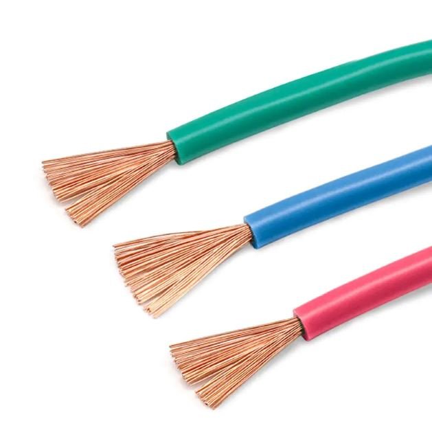
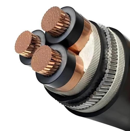
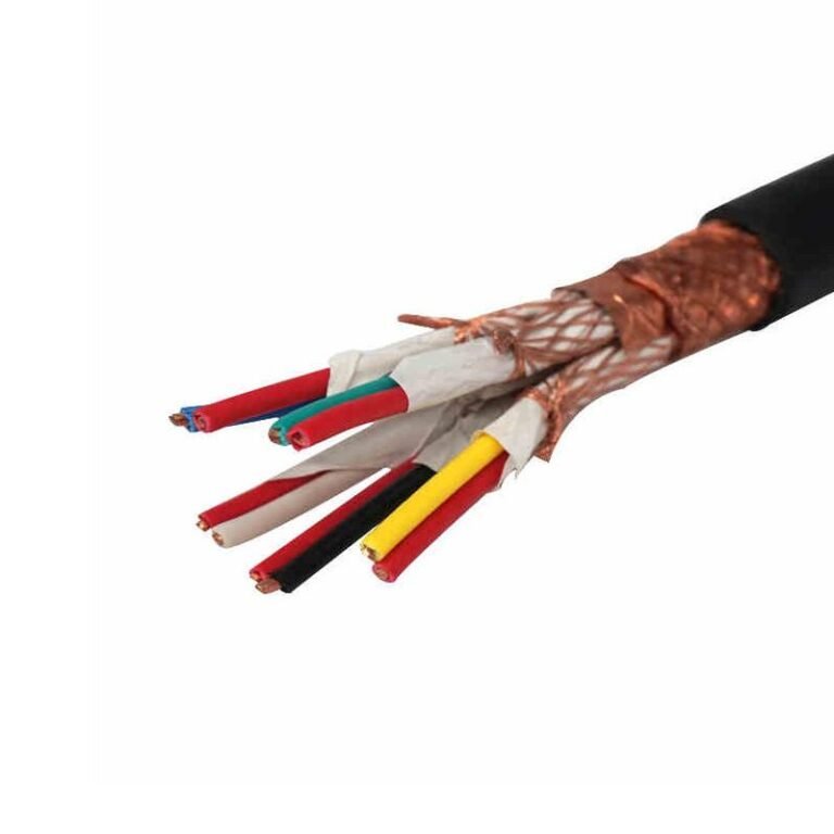
Misclassifying a 600 V system sounds harmless until it reaches purchasing, cable schedules, protection studies, and installation labor. Specify it as medium voltage and you may overbuy cable, terminations, switchgear space, and testing; treat it casually as “just low voltage” and you can miss insulation, fault-duty, and code requirements. The practical fix is to classify by the governing standard and the actual system voltage, not by shop-floor slang.
No, 600 V is normally not considered medium voltage. Under common IEC practice, low-voltage AC systems extend up to 1,000 V, and in North America medium-voltage cable ratings typically start above 1,000 V. Industrial 480 V and 575 V systems are therefore usually treated as low-voltage power distribution.
The confusing part is that “600 V” appears on plenty of serious equipment: large motors, MCCs, VFD feeders, tray cable, mining cable, and heavy plant distribution. That makes it feel like a threshold. It is a threshold for many product ratings and procurement documents, but not usually the point where low voltage becomes medium voltage.
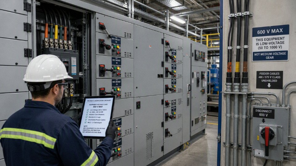
Voltage class boundaries
600 V sits on the low-voltage side of the boundary in the common systems engineers and buyers actually use. Under the IEC approach, it is below the 1,000 V AC low-voltage ceiling; in North American industrial purchasing, 600 V cable and equipment are normally bought as low-voltage products, while medium-voltage cable starts above 1 kV.
A 600 V AC cable is generally classified as low voltage under common IEC-style voltage boundaries and North American industrial cable purchasing practice.True
IEC low-voltage AC systems are commonly treated as up to and including 1,000 V, and North American medium-voltage cable categories generally begin above 1 kV. Always verify the governing project standard and local code language for the specific installation.
The IEC-style boundary: 600 V is low voltage
In IEC-based project language, low voltage commonly covers AC systems up to and including 1,000 V and DC systems up to and including 1,500 V. That places 600 V AC comfortably inside the low-voltage category, not sitting on the fence. This matters when a purchasing document calls for “LV power cable,” “0.6/1 kV cable,” or “low-voltage switchgear,” because those terms usually point the buyer toward a completely different product family than 3.6/6 kV or 8.7/15 kV medium-voltage cable.
The practical consequence is insulation system design. A low-voltage 600 V or 0.6/1 kV cable is selected around conductor size, insulation material, temperature rating, flame behavior, installation method, and mechanical protection. A medium-voltage cable brings in a different set of concerns:
- conductor screen and insulation screen,
- metallic shielding or concentric neutral design,
- partial discharge performance,
- stress control at terminations,
- shield grounding method,
- more specialized splicing and testing.
That is not just catalogue housekeeping. Put a medium-voltage cable into a low-voltage application and you may pay for insulation thickness, shield handling, larger bend radius, and termination labor that add no value. Put a low-voltage cable into a genuine medium-voltage circuit and the failure mode can be immediate, violent, and expensive. The boundary stops being a naming issue once electric stress and accessory design enter the job.
North American industrial practice: 600 V is still low voltage
In North American factories, 600 V equipment is normally treated as low-voltage equipment. The common plant voltages behind that are 480 V in much of the United States and 575 V or 600 V-class systems in parts of Canada and heavy industry. A maintenance electrician may say “600-volt gear” to distinguish it from 120/208 V panels, but that does not make it medium voltage in cable procurement terms.
Medium-voltage cable ratings in North American industrial work commonly start above 1 kV. Typical families include:
- 2.4 kV class,
- 5 kV class,
- 8 kV class,
- 15 kV class,
- 25 kV class,
- 35 kV class.
The jump from 600 V to 5 kV or 15 kV is not a small catalogue increment. MV cable is built around controlling the electric field. That is why shield continuity, termination workmanship, and test procedures become central. On a 480 V motor feeder, a slightly ugly termination may run for years if the lug is tight, the insulation is not nicked, and the enclosure stays dry. On a 15 kV feeder, a poorly prepared insulation shield edge or contaminated stress cone can create partial discharge and track its way to failure.
The trade-off is cost versus robustness for the actual voltage duty. A buyer may be tempted to overspecify “medium voltage” because it sounds safer, but that can increase cable diameter, tray fill, pulling tension, gland size, termination kit cost, and installation time. The preferred choice flips only when the system voltage, grounding method, transient exposure, or project standard truly requires the MV insulation and shielding system.
Code language, standards language, and buyer language do not always match
The National Electrical Code does not always use voltage-class wording the same way cable manufacturers, utilities, IEC documents, and EPC specifications do. Code rules may divide requirements by voltage thresholds, wiring method, occupancy, overcurrent protection, grounding, or equipment type rather than by the simple commercial terms “LV” and “MV.” A cable catalogue, meanwhile, will usually group products by rated voltage and construction.
For procurement, the safest habit is to specify the actual required rating and the applicable standard, not only the class name. A clean purchase description might include:
- nominal system voltage, such as 480 V, 600 V, 4.16 kV, or 13.8 kV;
- cable voltage rating, such as 600 V, 1,000 V, 2 kV, 5 kV, 15 kV, or 35 kV;
- AC or DC service;
- grounding arrangement;
- insulation type and temperature rating;
- governing standard or project specification;
- installation environment, such as tray, conduit, direct burial, tunnel, shipboard, mine, offshore platform, or mobile equipment;
- required approvals, markings, fire performance, and test documents.
This is where technical buyers save themselves from bad surprises. “Supply medium-voltage cable for plant distribution” is too loose if one site calls 600 V “MV” internally and another reserves “MV” for 4.16 kV and above. Written ratings beat local slang every time.
Nominal voltage is not the same as cable rated voltage
A 480 V system commonly uses 600 V rated cable because the cable rating is not a label for the exact operating voltage. It is the maximum voltage class for which the cable insulation system is designed and tested under specified conditions. The same logic applies when a 575 V motor circuit uses 600 V cable; the margin is intentional, not evidence that the system is medium voltage.
This distinction catches people during international substitutions. A buyer may see 0.6/1 kV cable in an IEC-style offer and compare it with 600 V cable in a North American bill of material. They are not always identical products, because standards, test methods, markings, conductor classes, fire requirements, and approvals may differ. Still, both belong in the low-voltage family for ordinary AC power distribution.
How common cable categories compare
| Cable category | Typical use | Construction and insulation expectation | Shielding and accessories | Testing and procurement notes |
|---|---|---|---|---|
| 600 V | 480 V and 575 V industrial feeders, motor circuits, control power, building distribution | Low-voltage insulation thickness; selected heavily by ampacity, temperature, environment, and flame rating | Usually unshielded power cable; standard lugs, glands, conduit fittings, tray accessories | Routine LV tests and markings depend on standard; confirm listing, approval, and installation method |
| 1,000 V / 0.6/1 kV | IEC-style low-voltage distribution, export projects, industrial plants, renewable balance-of-system depending on design | Still low voltage; often comparable application space to 600 V but under different standards | Usually unshielded unless a special design is specified | Watch equivalency carefully; do not assume a 600 V North American product satisfies an IEC 0.6/1 kV specification |
| 2 kV | Higher-margin low-voltage or special industrial service, some drive, mine, or renewable applications | Thicker insulation than 600 V; can be used where extra dielectric margin or specific standard calls for it | Often still not treated like classic MV cable, but construction varies by standard | Good example of why “above 600 V” does not automatically mean conventional MV construction |
| 5 kV | 2.4 kV and 4.16 kV distribution, large motors, plant substations | Medium-voltage insulation system with field-control requirements | Shielding and MV terminations commonly expected | Installation workmanship and acceptance testing become much more consequential |
| 15 kV | 12.47 kV and 13.8 kV distribution, utility-style plant feeders, campus systems | Heavier MV construction; insulation level may vary by grounding and fault-clearing design | Metallic shield, stress-control terminations, shield grounding plan | Specify insulation level, neutral or shield design, jacket, and test requirements clearly |
| 35 kV | Utility distribution, wind/solar collection, mines, large industrial networks | Substantially larger cable; mechanical handling becomes a project issue | Specialized terminations, joints, grounding, and test equipment | Pulling plan, bend radius, reel handling, and accessory availability can drive schedule |
The mechanism behind the category change is electric field stress. At low voltage, the insulation can usually tolerate field irregularities around the conductor without a semiconductive screen. As voltage rises, sharp interfaces, voids, dirt, and shield cutbacks concentrate stress. MV cable construction manages that field with smooth screens and controlled terminations. That is why the accessory kit on a 15 kV cable is part of the insulation system, not just a weather seal with a lug inside.
Phase-to-phase and phase-to-ground readings can change the interpretation
Voltage ratings are often discussed as phase-to-phase values, but insulation stress is strongly tied to phase-to-ground voltage and system grounding. In a solidly grounded three-phase system, the phase-to-ground voltage is the phase-to-phase voltage divided by roughly 1.732. A 480 V system is about 277 V phase-to-ground, which is comfortably within a 600 V cable’s intended use when the cable type and installation are correct.
Grounding gets more interesting in resistance-grounded and ungrounded systems. During a ground fault on an ungrounded system, the unfaulted phases can rise toward full phase-to-phase voltage relative to ground. On medium-voltage systems, that affects insulation level selection and whether a cable is specified as 100%, 133%, or 173% insulation level under some North American practices. For a 600 V low-voltage job, the same physics still exists, but the product categories and standards handle it differently. The engineer should not guess from the nameplate alone; the grounding method belongs in the cable schedule.
Common voltage bands, with boundary warnings
| Common band | Typical boundary used in many references | Typical examples | Procurement caution |
|---|---|---|---|
| Extra-low voltage | Often up to 50 V AC or 120 V DC, depending on standard and context | Sensors, controls, signaling, SELV/PELV-style circuits | Safety classification depends heavily on the governing standard |
| Low voltage | Common IEC-style range above extra-low voltage up to and including 1,000 V AC or 1,500 V DC | 120/208 V, 277/480 V, 575 V, 600 V, 0.6/1 kV | 600 V belongs here under the usual engineering classification |
| Medium voltage | Common industrial cable practice starts above 1 kV | 2.4 kV, 4.16 kV, 5 kV, 13.8 kV, 15 kV, 25 kV, 35 kV | Exact boundary and naming vary by standard, utility, and region |
| High voltage | Often above MV distribution levels; boundaries vary widely | Transmission or sub-transmission systems | Do not buy from the band name; specify rated voltage and standard |
| Extra-high voltage | Used for very high transmission classes | Grid transmission | Specialized system engineering, not ordinary plant cable procurement |
Utilities, mines, offshore projects, and steel or cement plants sometimes use their own shorthand. I have seen sites call anything above control voltage “high voltage,” and I have seen maintenance teams call 4.16 kV “medium” while reserving “high” for the utility yard. That language is fine over a radio during troubleshooting, but it is not good enough for a purchase order. For cables, terminations, switchgear, test requirements, and spares, the written voltage rating and governing standard are the contract language that matters.
Why the label differs
A 600 V system gets called different names because people are often describing different risks, not the same voltage classification. In formal cable and equipment terminology, 600 V is normally low voltage; on the plant floor, it may still be treated as “medium” because it is far above controls, instruments, and small building circuits.
A 600 V circuit can be classified as low voltage while still presenting serious shock and arc-flash hazards.True
Voltage class and hazard severity are not the same thing. Common IEC usage places AC low voltage up to 1,000 V, while arc-flash risk depends heavily on available fault current, protective-device clearing time, enclosure design, working distance, and maintenance condition.
Safety language is not the same as standards language
Electricians and maintenance supervisors often use voltage labels as risk shorthand. In a facility where most technicians work around 24 VDC sensors, 120 V receptacles, and 208 V panels, a 480 V motor control center or 575 V feeder feels like a different class of work. The PPE changes, the switching procedure gets tighter, and the consequences of a loose lug or missing dead front are much worse.
That perception is reasonable. It is just not the same as the formal voltage class used for cable rating, product certification, or tender compliance.
A 600 V cable or circuit can produce severe shock injury and damaging arc-flash energy. I have seen people become too casual around “low voltage” because the phrase sounds harmless. That is bad practice. Low voltage does not mean low hazard; it means the voltage falls inside a defined classification range.
The reverse can also happen. A higher-voltage circuit is not automatically the worst arc-flash case in the plant. Incident energy depends on several interacting factors:
- Available fault current from the transformer or upstream system
- Protective device clearing time, including delay settings
- Fuse or breaker current-limiting behavior
- Equipment enclosure geometry and bus spacing
- Working distance used in the study
- Maintenance condition, such as dirty gear, loose connections, or missing barriers
A 600 V switchboard with high fault current and slow clearing can be nastier, from an arc-flash standpoint, than a higher-voltage feeder protected by well-coordinated, fast-acting relays. Voltage is one input, not the whole hazard assessment.
Plant vocabulary grows out of local comparison
Inside a factory, “medium voltage” is sometimes used informally to mean “not controls and not lighting.” That happens especially in plants with a clear split between instrumentation wiring, small power, and production distribution.
A maintenance planner might group work this way:
| Local plant wording | What they may mean operationally | Formal procurement risk |
|---|---|---|
| Control voltage | 24 VDC, 120 VAC control circuits, PLC panels | Usually not confused with cable voltage class, but insulation and shielding still matter |
| Building power | Lighting, receptacles, office panels, small HVAC loads | May be specified by building-code language rather than industrial cable standards |
| Medium voltage | 480 V or 575 V motors, MCCs, feeders, process equipment | Can be misleading if buyers assume MV cable construction is required |
| High voltage | Utility service, substation equipment, large incoming feeders | Needs exact rating and standard; informal wording is unsafe for purchasing |
This language is not stupid; it is just local. A packaging plant that only has 208 V and 480 V may call 480 V “high voltage” because it is the highest voltage most mechanics touch. A mine, steel mill, or chemical plant with 5 kV, 13.8 kV, or 35 kV distribution would not describe 600 V the same way.
For engineering and purchasing documents, local shop language must be translated into rated voltage, applicable standard, conductor construction, insulation system, and installation conditions. That is where mistakes show up: someone asks for “medium-voltage power cable” when the actual load is a 600 V motor feeder, and the supplier either overquotes the wrong cable type or asks for clarification late in the schedule.
Legacy specifications keep old wording alive
Older plants often carry specification language from expansions done decades apart. One section may say “600 V power cable,” another says “low-voltage cable,” and a purchasing description says “medium-duty feeder cable” or “MV cable.” After a few shutdowns and copy-paste revisions, the terms get mixed.
Common reasons this survives:
- Old standards grouped 480 V and 600 V distribution separately from control wiring.
- Stores departments created item families such as “instrument cable,” “control cable,” and “power cable.”
- Maintenance crews used “heavy cable” to mean physically large conductors, not higher voltage rating.
- Procurement templates were built around vendor categories rather than engineering definitions.
- Plant expansions imported terminology from another country, consultant, or owner standard.
The commercial consequence is usually not theoretical. A wrong label can lead to:
- Overbuying cable with unnecessary shielded MV construction
- Under-specifying flame, oil, sunlight, or tray performance
- Missing the correct UL, CSA, IEC, or project-specific certification
- Ordering cable with the wrong insulation temperature rating
- Confusion over testing requirements, terminations, and accessories
There is a trade-off here. Using broad legacy categories can make internal ordering faster for routine replacement work, especially when the stores catalog is already stable. But for new projects, exports, or competitive bidding, that convenience becomes a liability if the description does not lock down the actual standard and rating.
Export projects add another layer of confusion
International projects create the worst terminology collisions. A buyer may say “medium voltage” because that is the local commercial habit. A European engineer may classify by IEC-style voltage ranges. A North American contractor may expect “medium voltage cable” to start above 1,000 V. A mining customer may use internal site classes that do not align cleanly with IEC, UL, CSA, or IEEE language.
The safe procurement question is not “Do you call this low voltage or medium voltage?” The safer question is:
- What is the system nominal voltage?
- What is the maximum operating voltage?
- What cable rated voltage is required?
- Which product standard or certification applies?
- Is the system grounded, resistance-grounded, ungrounded, or impedance-grounded?
- What installation method will be used: tray, conduit, duct bank, direct burial, flexible connection, festoon, reel, or portable service?
- What environmental and fire-performance requirements apply?

Cable suitability is broader than voltage class
A 600 V marking does not make a cable suitable for every 600 V job. It only addresses one part of the requirement. In practice, the cable may fail commercially or physically for reasons that have little to do with nominal voltage.
Engineers and buyers should check at least these items:
- Conductor size and ampacity: based on load current, grouping, ambient temperature, installation method, and derating rules.
- Insulation temperature rating: matched to conductor operating temperature, overload assumptions, and termination limits.
- Short-circuit withstand: verified against available fault current and protective-device clearing time.
- Environment: oil, chemicals, water, sunlight, mud, abrasion, rodents, vibration, or repeated flexing.
- Mechanical protection: tray, conduit, armor, sheath thickness, crush resistance, or pulling tension.
- Flame and smoke performance: especially for tunnels, buildings, ships, transit facilities, and crowded industrial cable trays.
- Certification and standard: IEC, UL, CSA, ICEA, IEEE, national project specifications, or owner-approved vendor lists.
- Termination compatibility: lug type, gland size, bend radius, shield requirements if any, and enclosure space.
The boundary is straightforward: once the job is a formally specified utility, mining, marine, rail, petrochemical, or export project, informal words such as “medium voltage,” “high voltage,” “power cable,” or “heavy-duty cable” are not enough. They can remain in conversation, but the purchase order and datasheet need the exact voltage rating, governing standard, construction details, and service conditions.
600V cable construction
A 600V cable is made 600V by its qualified insulation system and the product standard it is built and tested against, not by how thick the conductor looks or whether the cable feels “heavy duty.” Conductor size sets current-carrying ability; the voltage rating says the insulation and construction are suitable for the electrical stress and service conditions covered by the applicable cable specification.
A 600 V cable is defined mainly by its tested insulation system, not by conductor size.True
Conductor size affects ampacity and voltage drop, while the voltage rating is assigned to the completed insulation and construction under the applicable product standard and test regime.
In a plant, this distinction matters because two cables can both be marked 600V and behave very differently. A 4/0 welding cable, a 12 AWG tray control cable, a 600V building wire, and a marine power cable may share the same voltage class, but they are not interchangeable. The insulation compound, stranding, jacket, flame rating, oil resistance, and installation approval decide where each one belongs.

Conductors used in 600V cable
The conductor is still where most electrical buyers start, and for good reason: it drives ampacity, voltage drop, pulling weight, lug selection, and a large share of material cost. Common options include:
- Bare copper: common for building wire, control cable, tray cable, and general low-voltage power cable. It has high conductivity and familiar termination practice.
- Tinned copper: used where corrosion resistance, solderability, marine exposure, or higher moisture risk matters. It costs more, but I have seen it pay for itself in coastal plants where bare copper darkens quickly inside marginal enclosures.
- Aluminum: selected for feeders and larger power circuits where weight and cost matter. It needs correct lugs, oxide-inhibiting practice where required, torque control, and more attention to thermal expansion.
- Compacted copper or aluminum: reduces overall conductor diameter, which can help cable OD, conduit fill, and pulling tension. The trade-off is that terminations must be compatible with the compacted conductor shape and class.
- Flexible stranded conductors: used for portable cord, welding cable, battery cable, motor leads, and equipment wiring that sees vibration or movement.
- Class-specific stranding: fixed installations normally use less flexible stranding than movable service cables. A cable that pulls nicely through tray is not automatically suitable for a festoon, drag chain, or hand-carried tool cord.
The mechanism is simple but often overlooked: finer stranding reduces bending stress per strand and improves flex life, but it increases manufacturing complexity and may require ferrules, special lugs, or crimp dies. For a fixed motor feeder, ultra-flexible stranding may add cost without improving reliability. For a welding lead dragged across a fabrication bay, stiff building wire would fail mechanically long before its 600V insulation rating became the limiting factor.
Insulation and jacket materials
Insulation is the primary dielectric barrier. The jacket is the outer mechanical and environmental protection. Some cable types combine functions; others use separate insulation, fillers, shields, bedding, armor, and jacket layers.
| Material or construction | Common use in 600V cables | Practical buying notes |
|---|---|---|
| PVC insulation or jacket | Building wire, control cable, tray cable, general industrial cable | Economical and widely available; performance depends heavily on compound grade, temperature rating, flame rating, and oil resistance. |
| XLPE insulation | Low-voltage power cable, tray cable, industrial feeders | Good electrical and thermal performance; less forgiving than rubber-like compounds where repeated flexing is expected. |
| EPR insulation | Motor leads, portable power, industrial and utility-style low-voltage cable | More flexible than many XLPE constructions and good for wet or demanding service when properly specified. |
| CPE jacket | Mining, portable power, oil-exposed industrial cables | Strong oil, abrasion, and weather resistance in suitable compounds; usually more costly than commodity PVC. |
| LSZH compounds | Transit, tunnels, ships, data-heavy facilities, enclosed public spaces | Lower smoke and halogen acid gas under fire conditions; mechanical and processing properties vary by compound, so do not treat all LSZH jackets as equal. |
| Thermoplastic elastomers | Flexible cords, automation, cold-weather or moving applications | Good flexibility and abrasion resistance; check oil, coolant, UV, and flame approvals for the exact compound. |
| Nylon-jacketed building wire | Common single conductor building wire constructions | Thin nylon layer improves gasoline/oil resistance and pulling durability in many building-wire applications, but it is not a substitute for a heavy industrial jacket. |
| Oil-resistant industrial compounds | Tray cable, machine cable, motor supply cable | Important around hydraulic units, stamping presses, rolling mills, and machine tools where cheap jackets swell, crack, or soften. |
A 600V marking alone does not tell you whether the cable can survive sunlight on a pipe rack, coolant mist near a CNC line, washdown in a food plant, or diesel exposure at a generator set. Those requirements come from the material system and the standard markings: wet location suitability, sunlight resistance, oil resistance, flame test category, direct-burial rating, marine approval, mining approval, or other project-specific certification.
In procurement terms, “600V” is the electrical starting point; the service environment is what usually separates a correct cable from a costly substitution.
Temperature ratings, ampacity, and terminals
Insulation temperature ratings such as 60°C, 75°C, 90°C, and higher specialty ratings affect how much heat the cable insulation can tolerate without accelerated aging. They do not give unlimited ampacity by themselves. The usable current is governed by conductor size, insulation rating, installation method, ambient temperature, grouping, raceway or tray conditions, and the applicable code tables.
The trap is terminal compatibility. A 90°C insulated cable may still have to be ampacity-limited using a 75°C or 60°C column if the connected equipment terminals are only rated for that temperature. This comes up on MCC buckets, molded-case breakers, contactors, disconnects, and older control panels. The cable may be perfectly good, but the lug or device becomes the weak link.
Heat also accumulates in ways that are not obvious from a datasheet:
- Cables packed tightly in tray run hotter than spaced cables.
- Multiple current-carrying conductors in conduit need derating.
- High ambient temperature near ovens, furnaces, roofs, and outdoor cable trays reduces ampacity.
- Harmonic current in neutrals can add heating in some systems.
- VFD-fed motors may need cable construction suited to inverter duty, grounding, and EMC requirements, not just a voltage rating.
The preferred choice flips with installation conditions. A 90°C XLPE tray cable may be attractive for ampacity margin in a ventilated tray, while a more flexible EPR or elastomeric cable may be better for motor leads with vibration and tight bending at the terminal box. In a wet, oil-exposed pit, jacket chemistry may matter more than a higher dry-location temperature rating.
Shielding and special layers
Most 600V power and control cables are unshielded. At this voltage class, shielding is not normally needed to manage electric field stress the way it is in many medium-voltage cable designs.
Shielding is added for other reasons:
- Instrumentation noise control: foil or braid shields help protect low-level analog, thermocouple, load cell, and signal circuits from electrical interference.
- VFD motor leads: symmetrical grounds, shields, or armor may be used to control common-mode current, reduce radiated noise, and improve drive-system EMC behavior.
- Project EMC requirements: some facilities specify shielded low-voltage power or control cable near sensitive equipment.
- Special grounding or safety philosophy: certain marine, mining, or process installations may require defined grounding conductors, screens, armor, or protective layers.
Shielding brings a trade-off: better noise and EMC control, but larger OD, higher cost, more termination labor, and more chances for poor workmanship. A shield that is cut back randomly, grounded at the wrong point for the circuit design, or left with pigtails too long can disappoint everyone. The cable was not the problem; the installation detail was.
Common 600V cable families
A practical 600V specification usually names the cable family, not just the voltage. Typical families include:
- Building wire: single conductors for conduit and building distribution.
- Tray cable: multiconductor or multi-pair cable listed or approved for cable tray use, depending on jurisdiction.
- Control cable: machine, panel, interlock, and control circuit wiring.
- Portable cord: flexible service cable for tools, temporary power, and movable equipment.
- Welding cable: very flexible, high-current leads for welding circuits; not automatically approved for permanent building wiring.
- Battery cable: flexible low-voltage DC power cable, often used in energy storage, vehicles, and DC systems.
- Motor lead cable: flexible, heat-resistant leads between motor windings, junction boxes, and supply connections.
- Instrumentation cable: pairs or triads, often shielded, for signals and process measurement.
- Marine cable: built for shipboard flame, smoke, oil, moisture, and mechanical requirements as specified.
- Mining cable: rugged flexible cable for harsh mechanical abuse, abrasion, and wet service.
- Low-voltage power cable: feeders and distribution circuits for industrial, commercial, utility, and infrastructure projects.
Environmental features can be more decisive than voltage rating. Flame spread, smoke density, halogen content, oil resistance, sunlight resistance, moisture resistance, abrasion resistance, chemical resistance, termite protection, rodent protection, and direct-burial suitability are all construction choices. They should be specified from the actual route: indoor tray, outdoor ladder rack, underground duct, direct burial, wet trench, moving machine, marine deck, mine face, or chemical area.
The boundary is worth stating plainly: this discussion holds for common 600V low-voltage cable practice, but the exact acceptable construction depends on the governing standard, local code, authority having jurisdiction, equipment manual, and project specification. Before approving an alternate cable, check the full marking string and datasheet against the installation method, not only the voltage number printed on the jacket.
Procurement consequences
Buying “medium-voltage cable” for a true 600 V circuit usually creates cost, fit-up, and compliance problems without improving the installation. A 600 V order should be specified as 600 V cable, or by the exact applicable standard and rating, then matched to the system voltage, installation environment, and certification market.
The practical damage starts with geometry. Medium-voltage cable is normally designed around thicker insulation systems, shielded constructions, stress control accessories, and different test requirements. That can mean a larger outside diameter, heavier drums, larger tray fill, wider bend radius, different glands, different terminations, and longer pulling setup. On a crowded motor control center retrofit, I have seen the accessory issue cause more grief than the cable price itself: the cable arrives sound, but it will not fit the existing lugs, conduit seals, cable glands, or panel entry space without rework.
There is also a purchasing conflict. If the requisition says “MV cable, 600 V,” one supplier may quote a true medium-voltage product because that is what “MV” means in their catalog, while another may quote a low-voltage 600 V product because they read the voltage rating first. Now the bids are not technically equal. Procurement may think one supplier is expensive, when in fact the two quotes are for different cable families.
For a 600 V project, the buyer should specify the required 600 V cable construction and standard, not use “medium voltage” as a shortcut. The only time the higher class is justified is when the engineering specification intentionally requires it for a defined reason such as insulation coordination, owner standardization, unusual transient exposure, or a documented site rule.
A supplier cannot quote a responsible 600 V cable from the voltage alone. At minimum, the request should give enough information for the manufacturer to select conductor, insulation, jacket, testing, marking, packing, and documentation without guessing.
Key procurement data should include:
- Rated voltage and actual system voltage
- State the cable rating, such as 600 V, and the circuit voltage, such as 480 V AC or 575 V AC.
- Identify grounded, ungrounded, or resistance-grounded systems if the project specification treats these differently.
- AC or DC service
- DC circuits, including battery systems, rectifier outputs, and solar-related applications, may need different insulation review, polarity marking, or standard references.
- Conductor material and size
- Copper or aluminum.
- Size in AWG/kcmil, mm², or both if the project crosses markets.
- Class of stranding if flexibility matters.
- Core count and arrangement
- Single-core, multi-core, with or without ground conductor.
- Neutral, control cores, pilot cores, or communication elements if included.
- Insulation and jacket
- PVC, XLPE, EPR, rubber, LSZH, oil-resistant, sunlight-resistant, mud-resistant, or chemical-resistant compounds as applicable.
- Do not assume one compound name means the same performance under every standard.
- Shielding, armor, and mechanical protection
- Usually not required for ordinary 600 V power cable, but sometimes needed for VFD noise control, mechanical abuse, mining, shipyard work, direct burial, or rodent exposure.
- Specify copper tape, braid, wire armor, steel tape armor, aluminum interlock armor, or other required construction.
- Flame, smoke, halogen, and fire-performance requirements
- Flame test category, low-smoke requirement, halogen-free requirement, circuit integrity requirement, or tunnel/railway fire rule where applicable.
- Installation method
- Tray, conduit, duct bank, direct burial, messenger-supported, flexible machine connection, festoon, reeling, offshore topside, or indoor panel wiring.
- Pulling tension, sidewall pressure, and minimum bend radius become commercial issues when the drum size and route are fixed.
- Ambient and operating conditions
- Temperature range, wet or dry location, oil mist, coolant, UV exposure, salt spray, chemicals, vibration, flex cycles, altitude, and expected service life.
- Applicable standards and certification marks
- Name the exact standard edition if the project controls it.
- State required marks on the cable print legend and certificates, not only in a general note.
- Packaging and delivery schedule
- Drum type, maximum drum diameter, cut lengths, pulling direction, export packing, moisture protection, labeling language, inspection hold points, and delivery batches.
The standards list on a 600 V order can look messy because it often combines product standards, material standards, installation code references, and fire-test standards. They are not interchangeable.
| Reference often seen in 600 V orders | What it usually controls or supports | Procurement caution |
|---|---|---|
| UL | Product listing, marking, and safety certification for specific cable types | Confirm the exact UL category and whether the mark is required on the cable |
| CSA | Canadian certification and product requirements | A UL-listed cable is not automatically CSA-certified |
| NEC-related listings | Suitability for installation methods in the United States, such as tray, wet location, or sunlight resistance | The NEC is an installation code; it does not replace the cable product standard |
| ICEA | North American cable construction and test guidance, widely used in power cable specifications | Check the exact ICEA document and voltage class |
| NEMA | Industry standards and accessory or equipment-related references | Often appears with other standards rather than as the sole cable requirement |
| ASTM | Conductor and material test references, such as copper or aluminum properties | Usually supports material compliance, not complete cable approval |
| IEC 60502-1 | Power cables with extruded insulation for rated voltages from 1 kV up to 3 kV and related ranges depending on designation | Common for international low-voltage power cable procurement; verify voltage designation and local acceptance |
| IEC 60227 | PVC-insulated cables for rated voltages up to and including 450/750 V | Not a universal 600 V power cable answer; check project voltage and cable type |
| IEC 60245 | Rubber-insulated cables for rated voltages up to and including 450/750 V | Useful for flexible rubber cable families, but not automatically suitable for every 600 V installation |
| IEC 60332 | Flame propagation tests | Passing one part does not mean compliance with all fire-performance categories |
| IEC 60754 | Halogen acid gas testing | Relevant for halogen-free claims; pair with smoke requirements when needed |
| IEC 61034 | Smoke density testing | Low smoke and halogen-free are related in purchasing language, but they are separate test claims |
| National or project-specific standards | Local grid, railway, oil and gas, mining, marine, or owner specifications | These may override catalog assumptions and must be reviewed line by line |
A 600 V cable built for one market is not automatically acceptable in another. Certification marks, conductor sizing systems, flame tests, insulation designations, cable color codes, and documentation packages can differ enough to stop a shipment at site receiving. A cable marked in mm² to an IEC construction may be electrically suitable for a 480 V load, yet still fail a North American project requirement if the installation calls for a specific UL listing, AWG/kcmil sizing, or NEC-recognized cable type. The reverse can happen on export projects where a North American cable construction lacks the IEC test evidence or local approval documents requested by the owner.
A 600 V rating alone is not enough to confirm that a cable is acceptable for a specific country or project.True
Voltage rating confirms one part of the design envelope, but certification, installation code acceptance, flame performance, conductor sizing, marking, and project documentation must also match the purchasing jurisdiction and owner specification.
Custom 600 V cable is justified when the environment or duty cycle is outside ordinary building-wire or plant-distribution service. The mechanism is straightforward: the cable failure mode changes. In a dry electrical room, insulation aging and termination quality may dominate. On a washdown line, coolant and alkaline cleaner attack the jacket first. On a VFD motor feeder, shield design and grounding affect noise current paths before the insulation ever reaches its thermal limit.
Typical reasons to move beyond a catalog 600 V cable include:
- Harsh chemicals: oils, solvents, acids, caustic wash, hydraulic fluids, cutting fluids, or wastewater exposure.
- High flexing: robot dress packs, moving gantries, festoons, drag chains, portable equipment, and temporary power systems.
- Offshore or coastal service: salt spray, UV, mud resistance, fire-performance rules, and corrosion-resistant armor choices.
- Mining service: abrasion, crush risk, trailing duty, flame resistance, grounding conductors, and repair practices.
- Solar exposure: UV-resistant jackets, temperature derating, wet-location performance, and DC marking where relevant.
- Low smoke zero halogen requirements: indoor public infrastructure, tunnels, enclosed industrial escape routes, and shipboard-style owner rules.
- Railway or tunnel fire performance: smoke toxicity, flame spread, and sometimes circuit integrity, depending on the authority having jurisdiction.
- VFD noise control: symmetrical grounds, copper tape or braid shielding, low transfer impedance, and correct termination hardware.
- Special armoring: steel wire, steel tape, aluminum interlock, or non-magnetic armor depending on installation and single-core AC effects.
The trade-off is cost and handling. A tougher jacket, shield, or armor can improve survival in a bad location, but it may increase diameter, bend radius, termination time, and drum weight. The preferred choice flips when the installation route is benign and the owner only needs standard 600 V performance; then buying a specialty construction just adds cost and installation friction.
Quality documentation should be defined before the purchase order is released. If it is requested after production, the supplier may not be able to recreate every inspection point in the form the owner wants. For project cable, buyers commonly request:
- Product datasheet with rated voltage, construction, and operating limits.
- Cross-sectional drawing showing conductor, insulation, shield, armor, jacket, and overall diameter.
- Routine test report for the manufactured lot.
- Type test evidence where the standard or project specification requires it.
- Factory inspection report if there is a witness or hold point.
- Certificate of conformity.
- Material compliance statement, such as RoHS, REACH, halogen-free declaration, or project-specific restricted substance statement when applicable.
- Packing list with drum numbers, lengths, weights, and dimensions.
- Drum schedule matched to cable pull plans.
- Traceability records for conductor, insulation compound, jacket compound, production batch, and test results.
For large-volume procurement, the buyer should look beyond the catalog page. Capacity matters because cable projects fail commercially when extrusion slots, conductor supply, compound availability, and drum logistics do not line up with the construction schedule. A supplier may be technically capable of making the cable, yet still be the wrong choice for a multi-batch international order if it cannot hold dimensional consistency, repeat compound performance, maintain test throughput, and pack drums for the actual shipping route.
Supplier qualification should check:
- Production capacity
- Number of relevant extrusion lines, armoring lines, cabling lines, and test stations.
- Ability to split production into lots without changing materials mid-project.
- Conductor sourcing
- Copper or aluminum supply stability.
- Verification of conductor resistance, stranding, surface quality, and size tolerance.
- Compound control
- Approved insulation and jacket materials.
- Batch traceability, storage control, moisture control where relevant, and change-control procedure.
- Extrusion consistency
- Wall thickness control, concentricity, spark testing, surface quality, and diameter stability.
- This is where cheap cable often shows its character; inconsistent diameter makes glands, seals, and pulling calculations less predictable.
- Testing equipment
- Voltage test capability, conductor resistance testing, dimensional inspection, flame-test access where required, and documented calibration.
- Packaging and logistics
- Export drums, seaworthy packing, drum protection, length accuracy, cable-end sealing, and readable labels.
- For long ocean freight, poor packing can damage a good cable before it reaches the jobsite.
- After-sales technical support
- Response on datasheets, deviations, installation questions, test records, and site concerns.
- On international projects, time-zone response and document discipline are not luxuries; they affect commissioning.
Jinda can be positioned in this procurement discussion as a manufacturer rather than just a trading source. The company has cable manufacturing experience dating to 1987, multiple production bases, integrated R&D and manufacturing, export support, technical consultation, bulk project supply capability, and after-sales service for international customers. For buyers managing 600 V cable across different markets, those capabilities are relevant because the hardest part is often not identifying that 600 V is low voltage; it is aligning the cable construction, certification language, documentation package, and delivery plan so the material can be accepted and installed without surprises.
When 600V is insufficient
A 600V cable is insufficient whenever the circuit’s maximum operating voltage, grounding behavior, surge exposure, or waveform stress can exceed what that cable insulation system is designed and certified to withstand. The weak point is not always the nominal line voltage printed on the one-line diagram; it is often the transient, fault, or drive-output condition that the cable sees in service.
The first check is simple but often skipped during substitutions: the cable voltage rating must be suitable for the highest voltage that can appear between conductors and from conductor to ground. That includes:
- Normal voltage tolerance from the utility or generator
- System grounding method
- Single-line-to-ground fault behavior
- Switching and lightning surges
- Drive-generated pulse stress
- Whether the circuit is AC or DC
- The standard or listing required by the project jurisdiction
A cable that looks heavy, has thick jacket, or came off a “480V motor cable” reel is not automatically acceptable above 600V. Jacket toughness helps with abrasion and moisture. It does not prove the insulation has the correct dielectric rating, partial-discharge behavior, shield design, or listing for a higher-voltage circuit.
A nominal 600V circuit can require cable rated above 600V if waveform, grounding, surge, or equipment standard requirements expose the insulation to higher stress than the nominal voltage suggests.True
Cable selection is based on maximum electrical stress and applicable standards, not only the nameplate voltage of the load. VFD outputs, DC arrays, ungrounded systems, and delayed ground-fault clearing are common cases where nominal voltage is an incomplete selection basis.
Circuits that commonly move beyond ordinary 600V cable include:
- 690 V industrial motor systems, common in larger IEC-based plants, marine equipment, crushers, pumps, and export machinery. A 600V cable is below the system voltage before any tolerance or transient is considered.
- 1,000 V low-voltage distribution, seen in some industrial and renewable-energy layouts. It may still be called “low voltage” under IEC practice, but it is not a 600V cable application.
- 1 kV and 2 kV specialty circuits, including certain control power, drilling, mining, shipboard, and drive output systems. These often have application-specific cable standards rather than simple building-wire logic.
- Medium-voltage feeders, where ratings such as 5 kV, 8 kV, 15 kV, 25 kV, and 35 kV are a different cable family altogether, with shielding, insulation thickness, terminations, and test requirements to match.
- Utility collection systems, especially wind and solar collection networks. The collector cable may be medium voltage even if the inverter or skid equipment has familiar low-voltage components nearby.
- Large mining equipment, where trailing cables, reeling cables, shuttle car cables, and dragline cables can face higher voltage, mechanical abuse, wet conditions, and special grounding-conductor requirements at the same time.
Photovoltaic and energy storage systems deserve special caution because many buyers still think in AC plant categories. PV strings and battery racks may operate at 1,000 V DC or 1,500 V DC, and DC faults do not behave like AC faults. There is no natural current zero crossing every half cycle, so arc interruption and insulation tracking are different problems. Ordinary 600V cable is not suitable unless the actual circuit voltage is within the cable rating and the cable is listed or approved for that PV, battery, tray, wet-location, sunlight, temperature, and installation use. In practice, the printed cable legend matters here; “600V” plus a rugged black jacket is not the same thing as a PV wire or energy-storage cable with the right DC voltage and environmental markings.

VFD-fed motors create another trap. A plant may have a 480 V drive feeding a 480 V motor, yet the cable between the drive and motor can see steep pulses rather than a smooth sine wave. With insulated-gate bipolar transistor switching, the voltage rise time can be very fast. On long motor leads, wave reflection can cause peak voltage at the motor terminals well above the DC bus-derived pulse level, especially when cable impedance and motor impedance are poorly matched.
That mechanism is why some drive manufacturers specify 1 kV, 2 kV, or VFD-rated cable even on equipment most people casually call “600V class.” The issue is not just insulation thickness. A suitable VFD cable may need:
- Symmetrical grounding conductors or a robust grounding path
- Overall shield, copper tape shield, braid, or combination shield
- Low-impedance return path for high-frequency common-mode current
- Insulation designed to tolerate repetitive pulse stress
- Jacket and tray ratings suitable for the installation
- Correct termination method to carry shield current without pigtail inductance problems
The trade-off is cost, size, and termination labor. VFD-rated or 2 kV cable is less convenient than ordinary 600V tray cable: larger bend radius, more copper in grounds or shields, and more careful gland work. The choice flips when lead lengths are short, the drive manufacturer permits standard cable, and the installation has low reflected-wave risk. Once lead lengths grow, switching frequency rises, or nuisance bearing currents and insulation failures start showing up, the cheaper cable is not cheaper anymore.
Grounding method also changes the stress picture. A solidly grounded system with fast fault clearing is easier on cable insulation during a ground fault than an ungrounded or high-resistance-grounded system that may continue operating with one phase faulted. In an ungrounded system, the unfaulted phases can sit at elevated voltage to ground until the fault is found. In plants that let a ground alarm run until the next maintenance window — and many do, especially on continuous-process lines — that fault duration becomes part of the cable duty, not a paperwork detail.
Temporary overvoltage and surge exposure belong in the same review. Switching capacitor banks, large contactors, long outdoor feeders, lightning-prone sites, generator transfer events, and poor surge protection can all raise insulation stress. Cable standards and system protection studies handle these conditions differently by voltage class and installation type. If the circuit has unusual grounding or surge exposure, do not rely on a catalog shortcut; verify the required cable category against the equipment manual, project specification, and applicable electrical code or standard.
Cable accessories must match the duty as well. I have seen good cable installations ruined by casual accessory selection — a proper cable pulled into the tray, then terminated with a connector or splice kit that belonged on a different voltage class or environment. Check the complete circuit path:
- Glands and cord grips
- Lugs and compression connectors
- Splices and inline connectors
- Heat-shrink and cold-shrink kits
- Termination boots and stress-control parts
- Junction boxes and pull boxes
- Cable tray fill, spacing, bonding, and support hardware
- Enclosures, disconnects, drives, combiner boxes, and terminal chambers
Do not select those parts by conductor size alone. Creepage distance, clearance, temperature rating, wet-location suitability, shield bonding, fault-current capacity, and enclosure certification all have to line up with the circuit.
The risky shortcut is field substitution: “Use that 600V cable; it is already in stores.” That may get a machine running by Friday, but it can leave the plant with insulation breakdown, tracking, nuisance trips, premature aging, failed inspection, warranty rejection, or a serious arc-flash and shock hazard. If the circuit is 690 V, 1,000 V, 1,500 V DC, VFD output with long leads, resistance-grounded with delayed clearing, or connected to a medium-voltage system through special equipment, treat 600V cable as suspect until the actual rating and listing are verified.
Installation safety checks
Start with the uncomfortable truth: a 600 V circuit is usually classified as low voltage, but it is not a low-risk circuit. In a plant, 480 V or 575 V feeders can deliver enough fault current to vaporize metal, burn switchgear, and kill a worker who treats the label casually. Work should be done by qualified electrical personnel under the site’s lockout and tagout procedure, with absence-of-voltage verification, arc-flash assessment, and PPE selected from the applicable safety program and equipment labeling.

Before a cable leaves the drum, the crew should confirm the basics. A surprising amount of trouble starts with “close enough” cable pulled into a tray because the shutdown window was tight.
- Cable marking: Check the printed voltage rating, conductor count, conductor material, insulation type, temperature rating, flame rating where required, and any tray, sunlight, oil, or wet-location markings.
- Applicable standard compliance: Match the cable to the project specification and local code requirements. Do not assume a cable acceptable in one country is automatically acceptable in another installation.
- Conductor size and configuration: Confirm ampacity basis, voltage drop allowance, grounding conductor arrangement, neutral sizing, and whether parallel runs are truly matched.
- Drum and shipping condition: Look for crushed flanges, nails, broken lagging, displaced end caps, water stains, or cable ends left unsealed.
- Storage condition: Cable stored outside with an open end can wick moisture under the jacket. In cold weather, some jackets also become less forgiving during handling.
- Bend radius and pulling tension: Verify against the manufacturer’s data, not a rule of thumb from a different cable family. Over-tensioning stretches conductors and can create insulation damage that will not show up until the load heats and cools for a few cycles.
- Installation route: Walk the route before pulling. Look for sharp tray edges, hot pipe crossings, oil exposure, pinch points at equipment skids, and future maintenance access.
During installation, control the mechanical abuse. The cable may be electrically correct and still fail early if it is dragged across punched tray burrs or kinked behind a motor control center.
- Use pulling lubricant compatible with the jacket and insulation system.
- Keep pulling direction and sheave diameter within the manufacturer’s limits.
- Avoid jacket cuts, flattened sections, birdcaging, and tight tie-wrap compression.
- Maintain required separation from incompatible circuits, such as control, instrumentation, communication, or circuits with different insulation systems where the code or project standard requires segregation.
- Check tray fill and conduit fill before the pull, especially on retrofit jobs where “one more cable” has been added for years.
- Maintain grounding and bonding continuity across trays, conduits, glands, junction boxes, and equipment frames.
- Use proper support spacing so cable weight is not carried by terminations.
- Add mechanical protection where forklifts, dropped tools, rotating equipment, or removable guards can contact the cable.
Terminations deserve slow hands and clean work. Use lugs that match the conductor material: copper lugs for copper, aluminum-rated or dual-rated lugs where aluminum is used, and oxide inhibitor where the lug manufacturer requires it. Strip without nicking strands, clean the conductor, use the specified crimp die or compression tool, and torque bolted lugs with a calibrated wrench. I have seen more nuisance heating from “strong mechanic tight” terminations than from undersized cable.
Check these termination details before energizing:
- Correct lug barrel size and conductor class compatibility.
- Proper crimp count, die index, and inspection marks where applicable.
- Heat shrink or insulating boot installed without gaps, scorching, or trapped contaminants.
- Insulation clearance and creepage distance maintained at terminals.
- Cable gland sealing suitable for the enclosure rating, environment, and cable jacket.
- Phase identification that matches drawings and plant convention.
- No stray strands, copper whiskers, foil scraps, or cut shield materials left inside the enclosure.
Commissioning tests should fit the cable type and the project standard. Typical checks include continuity, insulation resistance, polarity, phase sequence, grounding continuity, and functional testing under controlled energization. The insulation resistance test voltage and acceptance criteria should come from the cable manufacturer, governing standard, or commissioning specification; using an excessive test voltage because “that is what we always use” can damage equipment connected at the far end or mislead the team about cable condition.
Maintenance inspections are where a 600 V installation tells on itself. Look for:
- Overheating at lugs, disconnects, glands, and tight conduit exits.
- Discoloration, softened insulation, brittle jacket, or heat-shrink pulling back.
- Jacket cracking from UV, cold bending, chemical exposure, or age.
- Oil swelling, coolant attack, or solvent damage near machine tools and pumps.
- Abrasion where cable rubs tray edges, covers, frames, or vibrating equipment.
- Loose terminations after thermal cycling.
- Nuisance trips that correlate with rain, washdown, startup load, or specific machines.
- Insulation resistance decline over repeated tests, not just one isolated reading.
- Moisture ingress at unsealed ends, glands, underground pulls, or outdoor junction boxes.
- Recurring ground faults that disappear after reset but return under load or humidity.
The trade-off is practical: tighter inspection, better documentation, and correct termination tooling cost labor during installation, but they reduce unplanned shutdowns and fault-finding later. The opposite choice looks cheaper until the plant is tracing an intermittent ground fault across three cable trays during night shift production.
Medium-voltage cable practices should not be pasted onto standard 600 V work. Shield continuity tests, stress cone installation, partial discharge testing, and specialized MV terminations generally belong to shielded medium-voltage cable systems, not ordinary unshielded 600 V industrial cable. If a project specifies a special shielded 600 V design, then the supplier’s installation instructions and project test plan control; otherwise, applying MV habits blindly can add cost without improving reliability, and in some cases can create termination errors that were never part of the original cable design.
Frequently asked questions
Is 600V considered medium voltage?
No. In most formal cable and electrical classifications, 600V is treated as low voltage, not medium voltage. The practical reason this matters is simple: a 600V cable is normally specified, tested, marked, and documented as a low-voltage product, even though it can still be hazardous enough to kill a person or damage equipment badly.
600V is generally classified as low voltage rather than medium voltage in common industrial cable practice.True
IEC low-voltage AC practice commonly extends up to 1,000 V, and North American medium-voltage cable categories typically begin above 1,000 V.
Is 600V the same as 480V?
No. A 480V system is a common nominal industrial distribution voltage, while 600V is often the cable or equipment voltage rating used above that nominal value.
In practice, many 480V motor feeders, control panels, VFD output circuits, and plant distribution runs use 600V-rated cable. That does not mean the system is operating at 600V all the time; it means the insulation system is rated for service within that voltage class, subject to the applicable standard and installation conditions.
Can 600V cable be used on a 600V system?
Usually yes, if the cable is actually rated and approved for that application. Do not stop at the printed “600V” marking and call the purchase complete.
Check at least these items:
- Maximum operating voltage, including tolerance and abnormal operating conditions
- Grounding method, such as solidly grounded, resistance grounded, or ungrounded systems
- Applicable code or project standard
- Wet, dry, direct-burial, tray, conduit, sunlight, oil, or chemical exposure rating
- Conductor temperature rating and ampacity basis
- Listing, approval, or certification required by the project
A cable that is fine in a dry indoor tray may be the wrong product for a wet pit, a movable machine connection, or a motor lead with high electrical noise from a VFD.
Can 600V cable be used for 1,000V?
No, not unless the cable is marked and documented for 1,000V or higher and is approved for the specific use. A 600V marking is not a “close enough” rating.
The insulation design, test voltage, standard compliance, and application listing all matter. If a project specification calls for 0.6/1 kV, 1 kV, or another defined rating, buy cable that matches that requirement rather than trying to justify a lower-voltage product after delivery.
Is 600V more dangerous than “low voltage” sounds?
Yes. “Low voltage” is a classification term, not a safety reassurance. A 600V circuit can produce fatal electric shock, deep burns, explosive arc-flash energy, and secondary injuries from falls or blast pressure.
On the plant floor, the risk is often made worse by ordinary maintenance conditions:
- Damp gloves or wet concrete
- Open panel doors during troubleshooting
- Missing dead-front covers
- Loose lugs from thermal cycling
- Metal dust, cable damage, or contamination inside enclosures
- Rushed testing with poorly rated meters or worn leads
Treat 600V work as serious electrical work requiring qualified personnel, isolation, verification, PPE, and site rules.
What voltage is medium-voltage cable?
In many industrial cable contexts, medium-voltage cable starts above 1 kV. Common product classes include 5 kV, 8 kV, 15 kV, 25 kV, and 35 kV cables.
Those cables are not just thicker versions of 600V cable. Medium-voltage constructions usually involve insulation shielding, conductor shielding, metallic screens or tapes, stress control at terminations, and different testing requirements. Termination workmanship becomes a major reliability factor; a rough knife cut or poorly prepared shield edge can create discharge problems that would not exist in the same way on a normal 600V feeder.
Does a thicker cable mean a higher voltage rating?
Not necessarily. Cable diameter can increase for many reasons that have little to do with voltage rating:
- Larger conductor size for ampacity or voltage drop
- More cores or control pairs
- Thicker jacket for abrasion, sunlight, oil, or chemical resistance
- Armor, braid, shield, or metallic tape
- Fillers used to make the cable round
- Flexible stranding or heavy-duty portable construction
The reliable checks are the cable marking, manufacturer datasheet, standard, and test documentation. I have seen plenty of physically large 600V power cables and relatively compact higher-voltage specialty cables; outside diameter alone is a poor buying criterion.
Should I buy 600V or 1kV cable?
Buy based on the governing system and specification, not only the nominal operating voltage. For a normal 480V or 575V industrial circuit, 600V cable may be correct if the standard, approval, environment, and installation method match. If the project document requires 1kV, 0.6/1 kV, or a specific IEC-style designation, then a 600V-only cable may create a documentation problem even if the electrical margin looks comfortable.
The preferred choice can flip when the project is export-driven, utility-connected, installed in a harsh environment, or subject to owner specifications that require harmonized IEC ratings. Procurement should settle this before purchase order release, not during site receiving inspection.
Does IEC treat 600V differently from North American standards?
The terminology and marking conventions differ, but 600V still generally falls within the low-voltage range under common IEC practice. IEC low-voltage AC classification is commonly understood up to 1,000V, while North American cable purchasing often separates familiar 600V low-voltage products from medium-voltage products above 1,000V.
For international projects, do not translate ratings casually. Ask whether the required cable is 600V, 1,000V, 0.6/1 kV, or another exact designation, and tie that to the named standard in the purchase specification.
What information should I send to a cable manufacturer?
Send enough information for the manufacturer to select and document the cable without guessing. At minimum, include:
- Required voltage rating and applicable standard
- AC or DC service, if relevant
- Conductor size and material, such as copper or aluminum
- Number of cores, grounding conductor needs, and shielding requirements
- Insulation and jacket material preference, if specified
- Installation environment: tray, conduit, direct burial, outdoor, wet, oil exposure, chemicals, movement, or high temperature
- Required certifications, markings, test reports, and project documents
- Approximate quantity, drum length, packaging, and delivery destination
- Drawings, load schedule, cable schedule, or owner specification
- Any special constraints, such as bending radius, flame performance, armoring, or low-smoke halogen-free requirements
Clear input prevents the common procurement mistake: receiving a cable that has the right voltage number on the jacket but the wrong construction for the job.
Verify your cable rating
600 V is generally not medium voltage; in most industrial purchasing and engineering contexts it is a low-voltage cable rating used for 480 V, 575 V, and similar power, control, and distribution circuits. The practical risk is not the label itself, but buying cable against a vague voltage class instead of the actual system duty, standard, construction, and installation conditions.
A 600 V cable should normally be treated as low-voltage cable, not medium-voltage cable.True
IEC low-voltage AC systems are commonly classified up to 1,000 V, and many North American medium-voltage cable categories start above 1,000 V. Project specifications and local codes still need to be checked.
Before releasing a purchase order, run the rating through a short verification sequence:
- Confirm nominal voltage
- Identify whether the circuit is 480 V, 575 V, 600 V, 690 V, 1,000 V, or another system voltage.
- Do not rely only on panel labels; check the single-line diagram, motor nameplate, transformer secondary, or drive output data.
- Check maximum system voltage
- A system described casually as “600 V class” may have operating tolerances, regenerated voltage, or transient conditions that push the cable selection higher.
- If the document states “Um,” “Uo/U,” or “maximum operating voltage,” use that value, not the nickname.
- Identify AC or DC duty
- DC circuits, battery systems, rectifier outputs, and solar or traction applications may need different insulation assessment than standard 600 V AC plant wiring.
- High DC voltage should be reviewed carefully instead of assumed acceptable because the number looks familiar.
- Confirm grounding method
- Solidly grounded, resistance-grounded, ungrounded, and impedance-grounded systems behave differently during faults.
- Grounding affects insulation stress, fault-clearing assumptions, and sometimes the standard referenced by the buyer.
- Match the applicable standard
- Specify the required IEC, UL, CSA, GB, mining, marine, offshore, or project-specific standard.
- If the project references a medium-voltage cable standard, do not substitute a 600 V cable without written engineering acceptance.
- Verify installation environment
- Check wet or dry location, direct burial, tray use, conduit fill, oil exposure, UV exposure, chemicals, flexing, abrasion, rodents, and mechanical impact.
- A cable can have the right voltage rating and still be wrong for the plant floor.
- Confirm ampacity and temperature rating
- Conductor size is not selected by voltage alone.
- Ambient temperature, grouping, tray spacing, conduit, insulation temperature class, and termination temperature limits all affect usable current.
- List required certifications and test documents
- State whether the buyer needs routine test reports, type test references, certificates, packing marks, drum schedule, datasheet, or third-party documentation.
Escalate the specification beyond a standard 600 V cable if any of these apply:
- The system voltage exceeds 600 V or is close enough that the project standard calls for 1 kV cable.
- The circuit uses high DC voltage, regenerative drives, rectifier outputs, or energy storage.
- Long VFD motor leads create reflected-wave voltage stress at the motor terminals.
- The installation has unusual switching transients, weak grounding, or frequent fault events.
- Mining, offshore, marine, tunnel, petrochemical, or utility approval is required.
- The specification explicitly names a medium-voltage standard or shielded MV construction.
Replace wording such as “supply suitable power cable” or “600 V / medium voltage cable” with exact procurement language:
- Rated voltage, such as 600 V, 0.6/1 kV, or specified medium-voltage class
- Conductor material and size
- Number of cores or conductors
- Insulation and sheath material
- Shielding, armor, screen, or grounding requirements
- Flame, smoke, oil, UV, water, or chemical resistance rating
- Installation method
- Required standard and certification
- Test documentation and packaging requirements
If your team is still deciding between 600 V, 1 kV, or medium-voltage cable, send Jinda the project specification, cable schedule, drawings, substrate or installation environment, operating voltage, load current, ambient temperature, required approvals, and any photos of the installation route or existing cable markings. Jinda’s technical and sales team can review the application requirements and support engineers, EPC teams, distributors, and bulk buyers with a cable recommendation, quotation, datasheet, or custom manufacturing discussion before procurement is locked.