Choose the wrong cable voltage class and a plant can inherit nuisance trips, overheated terminations, failed joints, and shutdowns that always seem to happen during a production push or bad weather. The direct repair bill is only part of it; lost output, emergency labor, damaged switchgear, and delayed commissioning often cost more. The practical starting point is understanding where medium voltage cable is actually used and what operating duty it must survive.
A medium voltage cable is used to carry electrical power above low-voltage levels, typically above 1 kV and commonly up to 35 kV, in distribution networks, industrial plants, renewable energy sites, mining systems, transport infrastructure, and large commercial facilities. It connects transformers, switchgear, motors, generators, feeders, and substations where current, distance, and reliability demands exceed low-voltage cable capability.
That sounds straightforward until you stand in front of a cable schedule with 6/10 kV, 8.7/15 kV, 12/20 kV, 18/30 kV, or 26/35 kV listed beside copper, aluminum, XLPE, armor, screens, and installation notes. The use case drives nearly every choice: voltage rating, insulation thickness, conductor size, short-circuit withstand, moisture protection, bending radius, pulling method, and the termination kit a crew will curse or praise later.
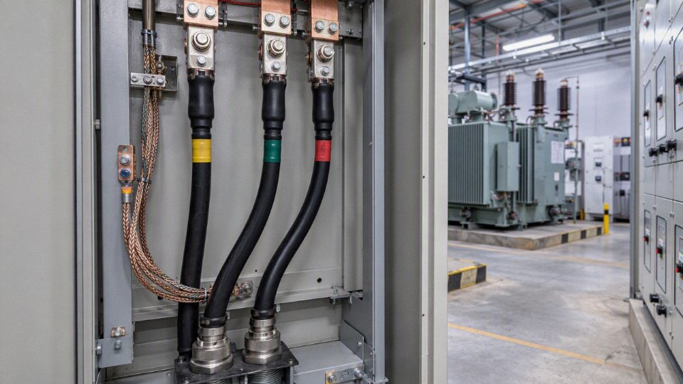
Voltage class and service role
Medium voltage cable sits in the part of the electrical system where power is still too large to move economically at low voltage, but not being transmitted across regional distances at high voltage. In operating terms, it is the site and distribution-network workhorse: feeding substations, transformers, large motors, renewable export circuits, and underground feeders that would be inefficient or physically awkward at 400 V or 480 V.
Low voltage cable normally serves final utilization loads: lighting panels, small drives, MCC buckets, packaged machines, building services, and branch circuits. Current is high for a given power level, so low voltage remains practical only when the distance and load size are modest. High voltage cable, on the other hand, is selected where the purpose is bulk transmission over long distances or major grid interconnection, with equipment, clearances, protection schemes, and civil works built around that duty.
Medium voltage fills the middle. A steel plant, port terminal, data center campus, mine, water treatment plant, or solar farm may receive power at a utility interface, distribute it around the site at 6 kV, 10 kV, 11 kV, 13.8 kV, 15 kV, 20 kV, or 33 kV, then step it down near the loads. The exact voltage is not chosen because one number is fashionable; it follows the connected load, feeder length, available switchgear, transformer ratings, local utility practice, fault level, and maintenance philosophy.
Cable voltage ratings are usually written in the form Uo/U, sometimes with Um stated as well. Uo is the rated voltage from conductor to earth or metallic screen. U is the rated voltage between conductors. Um is the highest system voltage the cable is expected to withstand under normal operating conditions, including permissible system variation.
For example, an IEC-style designation such as 8.7/15 kV means the cable insulation is rated for 8.7 kV conductor-to-earth and 15 kV conductor-to-conductor service. Its associated highest system voltage is verified from the applicable standard and manufacturer data, not guessed from the nameplate alone. Common medium voltage cable classes include 3.6/6 kV, 6/10 kV, 8.7/15 kV, 12/20 kV, 18/30 kV, and 26/35 kV. In some regional systems, medium voltage equipment classes extend toward roughly 46 kV, so project specifications should refer to the governing standard rather than a loose label.
A medium voltage cable rating such as Uo/U describes conductor-to-earth and conductor-to-conductor voltage stress, not simply a marketing voltage name.True
This is the standard way many medium voltage power cable ratings are expressed under IEC-style practice; final suitability still depends on the applicable cable standard, system grounding, and highest system voltage.
The power-transfer reason is simple but often underappreciated during early plant layouts. For the same megawatt demand, raising voltage lowers current. Lower current reduces I²R losses, voltage drop, thermal loading, and conductor size pressure. A 3 MW load at 400 V is a very different cabling problem from the same load at 10 kV. At low voltage, parallel runs, large trays, heavy bus duct, and large switchgear lineups appear quickly. At medium voltage, the feeder becomes more manageable, although the saving in copper or aluminum is partly exchanged for more expensive insulation, screened construction, terminations, testing, and qualified labor.
That trade-off is why medium voltage is common in these service positions:
- Utility distribution feeders: Underground or overhead-to-underground circuits carrying power through towns, industrial zones, campuses, and substations.
- Plant distribution loops: Ring or radial feeders connecting main substations to unit substations around a large site.
- Transformer primary connections: Cable from switchgear to distribution transformers, usually one of the most common industrial medium voltage duties.
- Generator export circuits: Connections from diesel, gas, hydro, wind, or solar generation equipment to a step-up transformer or collector switchgear.
- Large motor feeders: Pumps, compressors, crushers, mills, fans, and marine or mining drives where low-voltage current would be excessive.
- Underground distribution: Duct bank, direct-buried, tunnel, tray, or shaft installations where physical protection, moisture resistance, and joint quality become major reliability factors.
- Substation interconnections: Links between switchgear sections, transformers, capacitor banks, reactors, and metering or protection equipment.
System grounding changes how the cable insulation is stressed during faults, and this is one of the places where careless specification causes trouble. In a solidly grounded system, a phase-to-earth fault is expected to produce enough current for fast protective operation. The healthy phases normally do not sit at elevated voltage to earth for long. In a resistance-grounded system, fault current is deliberately limited, often to reduce equipment damage and arc-flash energy, but the relay scheme must still detect and clear the fault within the insulation design assumptions.
Isolated, ungrounded, or impedance-grounded systems need more attention. During a single line-to-earth fault, the unfaulted phases can experience increased voltage to earth until the fault is found and cleared. That affects the required Uo rating and the allowed earth-fault duration. A cable that is acceptable on a solidly grounded system may not be acceptable on an ungrounded or resonant-grounded network if faults are permitted to remain for extended periods. The cable data sheet, utility rules, and protection study need to agree; the buying description “15 kV cable” by itself is not enough.
Most medium voltage distribution is three-phase because industrial and utility power transfer is more efficient and equipment is designed around balanced three-phase operation. The cable arrangement may be three single-core cables, one three-core cable, or sometimes triplexed single cores depending on voltage, current, installation method, electromagnetic forces, pulling route, and termination layout. Single-core cables are easier to rate thermally in some duct bank and trefoil arrangements, but they require care with screen bonding, induced sheath voltage, metallic containment, and phase grouping. Three-core cables simplify routing and keep the phases together, though they are heavier, stiffer, and less forgiving in tight pulling routes.
A higher voltage cable is not automatically safer, more reliable, or better value. Overspecifying from, say, a proper 12/20 kV class to a higher class can increase outside diameter, minimum bending radius, pulling tension, termination kit size, joint bay space, and drum weight. It may also create inventory problems because spare joints, elbows, stress cones, separable connectors, and test adapters no longer match the rest of the site. I have seen projects save money on a “standardized” cable only to lose it during installation because the larger cable would not dress neatly into existing switchgear cable boxes.
The correct voltage class only holds its value when the whole electrical chain matches it: switchgear insulation level, transformer primary winding rating, protective relays, current transformers, surge arresters, cable screens, earthing system, terminations, joints, test voltage, and the operator’s fault-clearing practice. If any one of those is out of step, the cable may still look correct on a procurement schedule but perform poorly in service. For new builds, verify the network voltage, grounding method, maximum earth-fault duration, installation route, and termination interface before freezing the cable specification; for brownfield extensions, also check what the existing maintenance team actually stocks and knows how to joint.
Industrial and utility applications
Medium voltage cable shows up anywhere the load is too large or too spread out for practical low-voltage distribution, but not at transmission-grid voltage. The same 11 kV, 15 kV, or 33 kV class cable can sit under a city street, feed a kiln drive, loop through a wind farm, or power a mine conveyor; what changes is the construction around the conductor and insulation.
The same medium voltage rating can be used in very different industries, but the cable design may need different armor, sheath, flame performance, water blocking, conductor flexibility, or chemical resistance.True
Voltage rating mainly addresses electrical stress and insulation coordination. Installation environment, movement, fire exposure, soil moisture, chemicals, mechanical abuse, and maintenance access drive many of the construction choices.
Utility distribution networks
Utilities use medium voltage cable for the part of the network between primary substations and distribution transformers. In urban areas, this often means underground feeders leaving a substation, running through duct banks, pulling chambers, vaults, and ring-main units before stepping down to low voltage near buildings.
Common utility uses include:
- Underground primary feeders from substations to load centers, especially in cities, campuses, industrial zones, and high-density residential districts.
- Substation exit cables, where overhead conductors are not practical around switchgear yards, cable trenches, road crossings, or compact indoor substations.
- Urban distribution circuits using radial, loop, or network arrangements depending on reliability requirements and local utility practice.
- Rural feeders where buried cable is chosen for storm resilience, vegetation clearance reduction, road crossings, protected areas, or land-use restrictions.
- Network reinforcement, where an existing feeder is overloaded and a parallel or upgraded cable route is installed instead of rebuilding the whole overhead line.
- Overhead-to-underground replacement, common where reliability, public safety, aesthetics, or right-of-way limits justify the higher installed cost.
The mechanism is simple but commercially important: increasing distribution voltage reduces current for the same power transfer, and lower current reduces voltage drop and conductor heating. That is why a utility may carry power several kilometers at medium voltage, then step down near the customer instead of pushing high current at low voltage through oversized copper or aluminum.
The trade-off is civil work. Buried medium voltage cable improves weather exposure and land-use conflicts, but fault location, repair access, and route documentation become much more serious. A poorly mapped underground joint can turn a two-hour switching operation into a night shift with excavation permits, traffic control, and a crew waiting on the backhoe.
Industrial plants and process sites
Heavy industry uses medium voltage cable because plant loads are concentrated, motors are large, and sites are physically spread out. Steel mills, cement plants, chemical plants, petrochemical facilities, paper mills, manufacturing parks, and mixed process plants often distribute at 6 kV, 10 kV, 11 kV, 15 kV, or 33 kV before stepping down near motor control centers and unit substations.
Typical industrial circuits include:
- Main incoming feeders from the utility point of supply to plant switchgear.
- Transformer primary cables feeding unit substations across the site.
- Large motor feeders for crushers, mills, ID fans, compressors, pumps, extruders, refiners, and kiln drives.
- Interbuilding distribution across process blocks, warehouses, utilities areas, workshops, and loading zones.
- Critical process auxiliaries such as cooling water, compressed air, boiler feedwater, and emergency systems.
- Expansion feeders installed with spare capacity for new production lines or added substations.
In a cement plant, for example, a medium voltage feeder to a raw mill motor faces different practical risks than a feeder inside a clean electronics campus. Dust ingress, cable tray loading, vibration near drives, hot process areas, and maintenance isolation all affect the cable specification. In a chemical plant, jacket compatibility and documentation may matter as much as ampacity because a cable route may pass near solvents, acids, caustic washdown, or classified-area boundaries.
The engineering mistake is treating “medium voltage cable” as one purchasable thing. A cable that is electrically adequate may still be wrong if it has the wrong sheath for hydrocarbons, no radial water barrier in wet duct, insufficient armor for direct burial, or a conductor class too stiff for repeated handling.
Mining, tunneling, and movable heavy equipment
Mining and tunneling are among the hardest services for medium voltage cable. Here the cable may be dragged, reeled, flexed, driven over, exposed to rock abrasion, or handled by crews in wet and dirty areas. Standard fixed-installation cable is usually the wrong starting point for mobile mining equipment.
Applications include:
- Trailing cables for mobile mining machines and large excavation equipment.
- Reeling cables for stackers, reclaimers, tunnel boring support equipment, and movable conveyors.
- Pump circuits in dewatering systems, sumps, shafts, and underground workings.
- Crusher and conveyor feeds where high starting loads and mechanical shock are common.
- Mobile substations that shift as the mine face or tunnel advance changes.
- Harsh-service fixed installations in drifts, galleries, shafts, and processing areas.
Here, conductor flexibility, sheath toughness, flame retardance, tear resistance, and abrasion performance become central. Cable selection also has a maintenance behavior attached to it: if operators drag cable around sharp steel corners or leave it under haul-truck paths, no insulation system will save the installation for long. Medium voltage mining cable usually needs a cable-handling plan, not only a purchase order.
Oil, gas, and petrochemical projects
Oil and gas projects use medium voltage cable across both upstream and downstream facilities. Refineries, upstream production pads, gas processing plants, compressor stations, export terminals, and offshore support systems all need compact, documented, robust electrical distribution.
Common uses include:
- Refinery and petrochemical unit distribution to substations, process units, tank farms, and utility blocks.
- Compressor station feeders for large electric motor-driven compressors and auxiliaries.
- Upstream production pad distribution where multiple wells, pumps, heaters, and control shelters share a power system.
- Gas processing plant circuits serving dehydration, refrigeration, compression, and fractionation equipment.
- Offshore-adjacent and marine-support systems where salt exposure, corrosion, fire behavior, and documentation are tightly reviewed.
- Hazardous-area-adjacent infrastructure, where the cable route may not be inside the classified zone but still must satisfy project specifications, glands, sealing philosophy, and inspection practice.
The voltage rating alone says little about whether a cable is acceptable on these projects. Buyers usually need manufacturer documentation, test records, sheath marking, material traceability, packing controls, and compliance with the project’s cable schedule. In my experience, procurement delays often come from incomplete technical submittals, not from the cable factory’s ability to make the product.
Renewable energy and energy storage
Wind, solar, and battery projects use medium voltage cable as the collection and interconnection layer. Individual generating units produce power at lower voltage or inverter output voltage, then step up and collect power through medium voltage circuits before reaching the project substation.
Typical renewable uses include:
- Wind turbine collection systems, often buried between turbine transformers and sectionalizing cabinets.
- Solar farm collection circuits from inverter stations or step-up transformers to collection switchgear.
- Inverter step-up transformer connections where short but thermally significant cable runs carry high utilization.
- Battery energy storage plant feeders between PCS transformers, MV switchgear, and substation equipment.
- Renewable substation interconnection cables tying collection gear into main transformers or grid interconnection yards.
Renewable projects put a premium on route quantity and installation productivity. A solar farm may have long trench routes, repeated terminations, and many identical cable segments, so small differences in bending radius, drum length, pulling tension, and joint count affect labor hours. Wind projects add terrain, road crossings, soil thermal resistivity, and seasonal installation windows. The preferred cable may flip from the lowest material cost to the one that reduces joints or survives wet soil better.
Power generation facilities
Power stations use medium voltage cable inside the plant boundary as part of auxiliary and balance-of-plant distribution. This includes thermal power stations, hydropower stations, engine or gas-turbine plants, biomass facilities, and standby generation plants.
Representative circuits include:
- Generator auxiliary systems for pumps, fans, lubrication systems, excitation support, and starting systems.
- Balance-of-plant distribution feeding buildings, workshops, treatment systems, and electrical rooms.
- Transformer primary circuits between generator step-up auxiliaries, unit transformers, and MV switchgear.
- Cooling systems including circulating water pumps, cooling tower fans, and intake structures.
- Coal handling and fuel handling systems with conveyors, crushers, reclaimers, and dust-heavy cable routes.
- Hydropower station circuits where moisture, vertical routing, and access tunnels affect sheath and support design.
- Standby generation systems for hospitals, utilities, industrial plants, and data centers requiring reliable transfer paths.
Generation facilities are not always high-cycle cable environments, but reliability expectations are high. A failed auxiliary feeder can trip a unit even though the main generator and transformer are healthy. That is why cable routing separation, fire barriers, termination quality, and testing records carry practical weight.
Rail, metro, transport, ports, and logistics infrastructure
Transport systems use medium voltage cable to move power along long corridors and into concentrated operating loads. Rail and metro systems may use medium voltage distribution for traction power substations, station services, tunnel equipment, ventilation, pumping, signaling power supply interfaces, and depot facilities.
Applications include:
- Traction power substations and feeder links to rectifiers, transformers, and switchgear.
- Tunnel distribution for ventilation fans, drainage pumps, lighting supply equipment, and emergency systems.
- Station power systems serving escalators, HVAC, platform systems, and commercial areas.
- Airport infrastructure including terminals, baggage systems, central utility plants, and airfield support.
- Ports and container terminals feeding cranes, reefer yards, shore power systems, workshops, and substations.
- Electrified logistics facilities with high charger density, automated warehouses, and large HVAC or compressor loads.
Fire performance and smoke behavior can be especially sensitive in tunnels, stations, and enclosed public infrastructure. The buyer should not assume a standard industrial sheath is acceptable; project specifications and local codes usually define flame spread, smoke, acidity, circuit integrity, or installation method requirements.
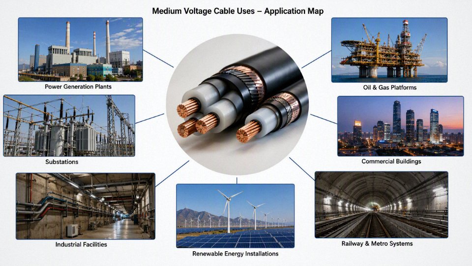
Data centers and large commercial campuses
Data centers, hospitals, universities, airports, semiconductor support buildings, and large commercial campuses often use medium voltage distribution because low-voltage service currents become awkward at scale. Medium voltage service entrances feed main switchgear, then redundant feeders distribute power to unit substations near load blocks.
Typical uses include:
- Medium voltage service entrances from utility supply points.
- Redundant feeders arranged for N+1, 2N, ring, or selective coordination strategies depending on the facility design.
- Unit substation connections close to IT halls, mechanical rooms, laboratory buildings, or production zones.
- Emergency power distribution from generators to paralleling switchgear and downstream substations.
- Large HVAC plant supply for chillers, cooling towers, pumps, and central energy plants.
The trade-off here is between redundancy and complexity. More feeders and switching options improve maintainability, but they also increase termination count, testing scope, protection coordination work, and the chance of human switching error. Good labeling and disciplined commissioning matter as much as cable construction.
Water, wastewater, desalination, and municipal networks
Municipal infrastructure uses medium voltage cable where motors are large and the equipment is distributed across a wide site or district network. Pumping stations, wastewater treatment plants, desalination facilities, flood control stations, and district utility systems are common examples.
The service conditions are often wet, corrosive, and maintenance-constrained. Cable may run through ducts with standing water, galleries with hydrogen sulfide exposure, outdoor trays, buried routes, and rooms that see washdown or flooding. Water blocking, sheath choice, armor, corrosion protection, and gland sealing deserve attention because a municipal site may be expected to run for decades with limited shutdown windows.
Temporary and movable power systems
Temporary medium voltage cable is used when high power must be moved before permanent infrastructure is ready, or when the supply point changes with the job. Construction substations, emergency power bypasses, shipyards, event infrastructure, temporary industrial expansions, and mobile equipment feeds all fall into this category.
Key design differences include:
- Repeated handling, so conductor flexibility and jacket toughness are more important than in a fixed duct installation.
- Temporary terminations and couplers, which must match voltage class, fault duty, environmental exposure, and safe operating practice.
- Traffic exposure, requiring ramps, protection, routing barriers, or burial depending on site layout.
- Fast deployment, where drum size, lifting points, cable weight, and crew familiarity affect actual install time.
- Inspection frequency, because damage from forklifts, welding slag, sharp ballast, and careless dragging is common.
The boundary on all of these application categories is the project specification and the actual installation environment. A cable schedule that only lists voltage, conductor size, and core count is not enough for reliable selection; the useful questions are where the cable will be installed, how it will be pulled or moved, what can attack the sheath, what fire behavior is required, and how painful a failure will be to repair.
Cable construction and material choices
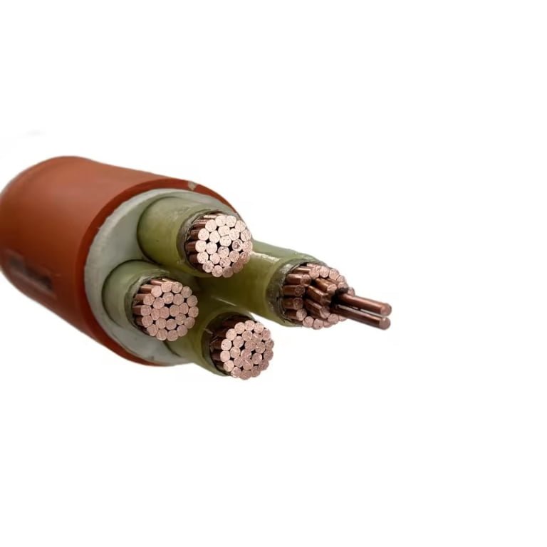
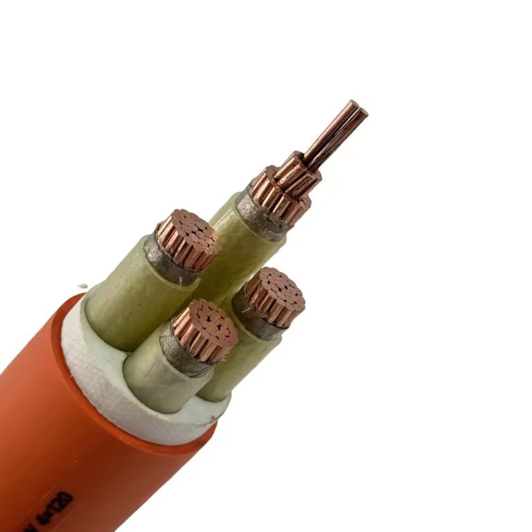
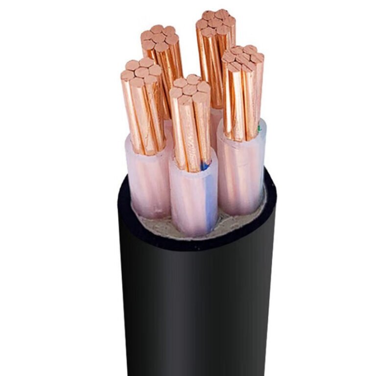
A medium voltage cable is not just “copper with insulation”; it is a controlled electrical system built in layers. The conductor carries load, but the screens, insulation, metallic shield, water barriers, armor, and sheath determine whether the cable survives switching surges, wet ducts, pulling damage, earth faults, and 20 years of imperfect maintenance.
Conductor: copper or aluminum
Copper is still the easier material to live with at terminations, especially where space is tight, short-circuit duty is high, or maintenance quality is mixed. It has higher conductivity than aluminum, so the same ampacity can usually be achieved with a smaller conductor size, lower joint resistance risk, and more compact glands and lugs. The trade-off is obvious on any procurement sheet: copper is heavier and usually more expensive, sometimes painfully so on long feeders.
Aluminum earns its place when route length, weight, and budget dominate. A correctly sized aluminum conductor can deliver the same duty as copper, but it needs a larger cross-section, compatible lugs, proper oxide removal, joint compound where specified, and torque control. I have seen good aluminum systems run for decades; I have also seen overheated terminations caused by someone treating aluminum like copper during a shutdown at 2 a.m.
Key differences that affect buying and installation:
| Factor | Copper conductor | Aluminum conductor |
|---|---|---|
| Conductivity | Higher, smaller size for same resistance | Lower, larger size needed |
| Weight | Heavier, harder on trays and pulling setups | Lighter, useful for long routes and aerial or riser work |
| Cost | Higher material cost, volatile with metal market | Usually lower conductor cost |
| Termination practice | More forgiving, but still needs correct lugs and torque | Needs aluminum-rated accessories, surface preparation, and torque discipline |
| Short-circuit behavior | Better thermal capacity in compact sizes | Can meet duty if sized correctly, but larger section may be needed |
| Procurement trade-off | Higher upfront cost, often lower installation risk | Lower cable cost, sometimes higher accessory and workmanship sensitivity |
The preferred choice flips when installation constraints become more expensive than metal cost. In a congested substation trench, copper may save space and labor. On a long solar plant collector route, aluminum can be commercially sensible if voltage drop, fault current, and termination quality are properly engineered.
Conductor shape and class
Conductor shape affects cable diameter, flexibility, current distribution, and how the cable behaves during pulling. For medium voltage work, the usual options are:
- Compact round stranded conductors: Common for single-core and three-core cables. Compaction reduces diameter and helps keep the insulation layer uniform.
- Non-compacted stranded conductors: Easier to manufacture and flexible enough for many applications, but with a larger overall diameter for the same nominal size.
- Sector-shaped conductors: Used mainly in three-core designs to reduce overall cable diameter. They are efficient in space, but bending and termination preparation need more care.
- Flexible stranded conductors: Useful for mobile equipment, mining, temporary power, wind tower loops, and tight installations. They cost more and require compatible glands, lugs, and stress control accessories.
Conductor class is not a catalog detail to ignore. Finer stranding improves handling and bendability, but it can complicate compression lug selection and increase the risk of strand damage if the installer uses the wrong die set. Stiffer compact conductors are often better for fixed distribution feeders because they terminate cleanly and hold shape, but they demand larger bend radius and better route planning.
Conductor screen and insulation
The conductor screen is a semiconductive layer applied over the conductor before the main insulation. Its job is to smooth the electric field. Without it, the field would concentrate around strand edges and small surface irregularities, creating localized electrical stress inside the insulation.
XLPE is the mainstream insulation choice for many modern medium voltage cables because it combines good dielectric strength, thermal performance, mechanical stability, and broad manufacturing availability. For typical utility distribution, industrial feeders, renewable energy collection circuits, and infrastructure projects, XLPE is often the default starting point.
EPR and related rubber-based insulation systems still matter. They are selected where flexibility, moisture tolerance, or special operating conditions justify the cost and design differences. Some mining, shipboard, mobile, or high-flex service cables may favor rubber insulation systems because the cable is not sitting quietly in a duct for its whole life.
The most important reliability feature is often the quality of the insulation-screen interfaces, not the visible thickness of the cable. Voids, contamination, scorch marks, poor extrusion centering, or microscopic protrusions can initiate partial discharge even when the outside of the cable looks perfect. That is why controlled extrusion, clean material handling, and electrical testing are not paperwork exercises; they are what prevent a feeder from becoming a buried failure investigation.
For medium voltage cables, conductor and insulation screen quality strongly affects partial discharge performance.True
This follows established medium voltage cable design principles: semiconductive screens control the electric field at conductor and insulation boundaries. Defects, voids, or contamination at these interfaces can create local electrical stress and partial discharge.
Insulation screen and metallic screen
The insulation screen is another semiconductive layer, applied over the insulation. Together with the conductor screen, it creates a controlled radial electric field through the insulation wall and provides a uniform interface for the metallic screen or shield.
The metallic screen has several practical jobs:
- It provides a path for charging current and earth fault current, subject to proper sizing.
- It helps manage touch voltage when bonded and earthed correctly.
- It reduces electromagnetic interference to nearby control and communication circuits.
- It gives the cable a defined electrical boundary, which matters for testing and protection design.
Common screen and sheath arrangements include:
| Metallic screen option | Where it is commonly considered | Main trade-off |
|---|---|---|
| Copper tape screen | Distribution cables, many fixed installations | Good coverage, but limited fault current capacity unless designed accordingly |
| Copper wire screen | Higher earth fault duty or bonding flexibility | Better current capacity, larger diameter and higher cost |
| Aluminum laminate screen | Moisture barrier plus screening in some designs | Needs correct bonding and accessory compatibility |
| Lead sheath | Wet, chemically aggressive, or critical service in some legacy and special applications | Excellent radial barrier, but heavy, costly, and subject to handling and environmental considerations |
| Combined screens and armor | Project-specific utility or industrial feeders | Must coordinate fault duty, mechanical load, and bonding practice |
Screen sizing cannot be guessed from voltage alone. It depends on system grounding, earth fault current magnitude, protection clearing time, bonding arrangement, cable length, installation grouping, and allowable screen temperature. This is one of those procurement questions where a cheap underspecified screen can become a protection and safety problem later.
Water blocking and moisture protection
Moisture does two types of damage. It can travel along the cable length after sheath damage, and it can penetrate radially through the outer layers over time. Medium voltage cables installed in wet soil, ducts that flood every rainy season, tunnels with condensation, or direct burial routes need water resistance matched to the actual exposure.
Typical measures include:
- Longitudinal water blocking: Swellable tapes, yarns, or powders limit water migration along the conductor or screen area after damage.
- Radial water blocking: Aluminum plastic laminate, metallic sheaths, or special barrier layers reduce moisture penetration through the cable wall.
- Water-resistant sheathing: PE or specially compounded sheaths are often preferred for wet soil and direct burial.
- Sealed accessories: Joints and terminations must match the cable water-blocking design, otherwise the best cable construction is defeated at the first splice.
The boundary is simple: water blocking reduces risk after damage or exposure; it does not make poor trench drainage, crushed ducts, or careless jointing harmless.
Armor and mechanical protection
Armor is selected from the installation method, not from habit. A cable sitting in a clean indoor tray does not need the same mechanical protection as one pulled through a rough duct bank, laid in rocky soil, or exposed to rodents and site traffic.
Common choices:
- Steel wire armor: Strong pulling and mechanical protection for many multi-core cables. It is common in direct burial and industrial environments.
- Steel tape armor: Good crushing resistance, often used where radial mechanical protection matters more than high tensile pulling load.
- Aluminum wire armor: Used for single-core AC cables where magnetic losses and heating from ferrous armor would be a concern.
- Unarmored construction: Suitable for ducts, trays, controlled indoor routes, or installations where external mechanical protection is provided by the civil design.
Steel around single-core AC cable deserves caution. Magnetic armor can heat due to induced currents and losses, so non-magnetic armor or different installation arrangements may be required. This is not a cosmetic cable choice; it affects operating temperature, ampacity, and long-term sheath life.
Outer sheath and fire performance
The outer sheath is the cable’s working jacket. It takes abrasion during pulling, sits in mud or sunlight, resists oil in a plant trench, and carries the flame or smoke performance required by the installation.
Typical sheath options include:
- PVC: General-purpose, economical, with broad use in industrial and distribution applications.
- PE: Good moisture resistance and toughness, often preferred for buried or wet routes.
- LSZH materials: Lower smoke and halogen-free behavior for tunnels, buildings, stations, and enclosed public infrastructure.
- Flame-retardant compounds: Reduce flame spread under specified test conditions.
- Oil-resistant sheaths: Used near refineries, workshops, ports, and machinery spaces.
- Termite-resistant or anti-rodent designs: Relevant for certain soil and tropical installations.
- UV-resistant sheaths: Needed for outdoor exposure, solar plants, rooftops, and open cable racks.
- Chemical-resistant sheaths: Selected for wastewater, chemical processing, ports, mining, and contaminated ground.
Fire wording is often abused in quotations. Flame retardance, LSZH behavior, fire resistance, and circuit integrity are different properties. A flame-retardant cable may limit flame spread but still produce smoke and acidic gases. An LSZH cable reduces smoke and halogen acid gas, but that does not automatically mean it maintains circuit operation during fire. Fire-resistant circuit integrity requires a specific cable system design and verification against the applicable standard and installation method.
Matching construction to project risk
Jinda’s value in medium voltage cable supply is not only producing a voltage rating on a drum. With R&D, production, testing, technical support, and project-specific cable design under one manufacturing system, Shandong Jinda Special Cable Group Co., Ltd. can align conductor material, insulation system, screen design, water blocking, armor, and sheath compound with the project’s route and electrical duty for international procurement.
For a factory owner or technical buyer, the practical specification path is to define the service first: voltage class, conductor material preference, fault level, installation method, wet or dry environment, fire requirement, mechanical exposure, and accessory standard. Once those are fixed, the cable construction becomes an engineering selection instead of a low-price guessing game.
Specification factors before purchase
A medium voltage cable order should not start with “how many meters and what size.” It should start with the electrical duty, installation route, fault level, accessories, documents, and delivery plan. The cheapest quoted cable can become the most expensive line item if it arrives with the wrong screen rating, drum length, sheath, test paperwork, or termination fit.
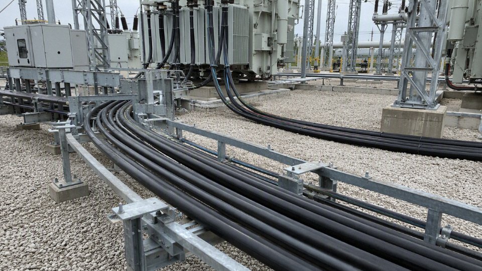
Electrical rating and system duty
Rated voltage is the first filter, but it is not just the nominal system voltage printed on the single-line diagram. Procurement should confirm:
- System nominal voltage, such as 6 kV, 10 kV, 11 kV, 15 kV, 20 kV, or 33 kV
- Highest system voltage used by the applicable standard
- Cable voltage designation, such as 6/10 kV, 8.7/15 kV, 12/20 kV, 18/30 kV, or 26/35 kV under common IEC practice
- Basic insulation level or impulse withstand requirement where specified
- System grounding method:
- Solidly grounded
- Resistance grounded
- Ungrounded or isolated neutral
- Resonant grounded
- Expected overvoltage exposure from switching, lightning, long feeders, capacitor banks, or VFD-driven equipment
- Governing standard, such as IEC, ICEA, AEIC, BS, VDE, GB, or a utility/project specification
The mechanism is simple enough but often ignored: grounding method changes how long a healthy phase may see elevated voltage during a single-line-to-ground fault. A cable that is acceptable on a solidly grounded network may not be the right insulation selection for an ungrounded or impedance-grounded system with extended fault operation. That is why a voltage class written as a single number is not enough for a purchase order.
A standard name alone is not a complete medium voltage cable specification.True
Standards define test methods, construction rules, and rating frameworks, but the purchaser must still define voltage class, conductor, screen, sheath, installation conditions, accessories, documentation, and project-specific requirements.
Load current, ampacity, and voltage drop
Ampacity depends on heat leaving the conductor, not just copper or aluminum cross-section. A cable in open air on tray behaves very differently from the same cable in a crowded duct bank under sun-baked concrete. In practice, the site installation method can move the safe current rating enough to change conductor size, drum weight, pulling tension, and cost.
Confirm these inputs before final conductor selection:
| Factor | Why it changes the order |
|---|---|
| Conductor size and material | Copper gives lower resistance and smaller diameter for the same current; aluminum is lighter and often cheaper but needs larger cross-section and compatible lugs. |
| Insulation temperature rating | XLPE systems are commonly rated for higher operating temperatures than older insulation types, but the actual allowable rating must match the cable design and standard. |
| Installation method | Direct burial, ducts, trays, tunnels, shafts, and air installation all dissipate heat differently. |
| Soil thermal resistivity | Dry sand, backfill, clay, and seasonal moisture changes can make a large difference. A nice-looking trench can still be thermally poor. |
| Ambient temperature | Hot climates, boiler rooms, rooftops, and sun-exposed cable ladders reduce margin. |
| Grouping and duct occupancy | Multiple loaded circuits heat each other. Spare ducts are cheap on paper; full duct banks are not. |
| Load profile | Continuous process load, cyclic crane duty, pump starting, and renewable feeder output have different heating patterns. |
Voltage drop needs the same discipline. Feeder length, load current, power factor, and motor starting current determine what the receiving equipment actually sees. A long 11 kV feeder to a pump station may run fine at steady load but sag during motor start if the source impedance and starting method were guessed. For sensitive drives, large motors, and process plants with tight uptime requirements, the acceptable voltage limit should be agreed with the electrical designer and equipment supplier, not decided after the cable is already on drums.
The trade-off is familiar: increasing conductor size improves losses, voltage drop, and thermal headroom, but it raises cable cost, drum weight, bending effort, pulling tension, gland size, and sometimes civil work. The preferred choice flips when energy losses and voltage regulation are worth more than the installed cost increase, especially on long feeders or continuously loaded circuits.
Short-circuit withstand and earthing design
Short-circuit rating is where many low-price offers fall apart. The conductor must thermally withstand the fault until protection clears, and the metallic screen or sheath must carry earth-fault current without overheating or damaging the insulation system.
Specify or verify:
- Maximum three-phase and earth-fault current at the cable location
- Protection clearing time, including backup protection where relevant
- Conductor short-circuit thermal withstand
- Metallic screen, tape, wire, or sheath fault-current capacity
- Earthing and bonding arrangement:
- Single-point bonding
- Both-end bonding
- Cross-bonding
- Special bonding for long single-core circuits
- Link boxes, surge voltage limiters, and bonding leads where required
- Requirements for shield continuity through joints and terminations
Single-core medium voltage cables need extra care because magnetic fields, sheath circulating currents, and bonding design can affect losses and heating. Both-end bonding is simple and robust, but it can create circulating current in metallic screens on long or heavily loaded circuits. Single-point or cross-bonded systems can reduce losses, yet they demand correct engineering, installation, labeling, and testing. A missing bonding link in the field is not a paperwork error; it can become a heating and safety problem.
This conclusion stops holding only when the project specification already defines the complete protection study, fault level, bonding method, and accessory package. If those items are still provisional, the cable screen and earthing design should not be treated as commodity details.
Installation environment and mechanical protection
Medium voltage cable spends most of its life being abused by its surroundings, not by the catalog page. The route survey should separate the installation into actual exposure zones:
- Indoor switchgear rooms with controlled environment
- Outdoor cable trays exposed to UV, rain, dust, and temperature swing
- Direct burial routes with stones, settlement, rodents, or termite risk
- Duct banks with high pulling friction and poor heat dissipation
- Tunnels with fire, smoke, and evacuation requirements
- Vertical shafts where cleating, weight, and bending radius matter
- Industrial areas with oil, solvents, acids, alkalis, or washdown water
- High-temperature zones near furnaces, boilers, steam lines, or rooftops
- Wet locations, flood-prone trenches, or permanently damp ducts
- Submarine-adjacent or coastal routes with salt atmosphere and corrosion exposure
- Mechanically exposed areas near forklifts, mobile equipment, or maintenance traffic
Armor and sheath selection should follow those conditions. Steel wire armor or tape armor may be chosen for mechanical protection in multicore cables, while non-magnetic armor or special arrangements may be needed for single-core AC circuits to avoid excessive heating. Sheath material selection depends on abrasion, UV, oil, chemical exposure, flame behavior, low-smoke requirements, termite resistance, and local code expectations.
There is no universal “best sheath.” A tough outer jacket that pulls well through ducts may not satisfy a low-smoke indoor tunnel requirement. A fire-performance sheath may cost more and need more careful handling during installation. In my experience, this is where procurement needs to resist simple equivalence claims unless the alternate material is checked against the actual route and project standard.
Cable arrangement: single-core or three-core
Single-core cable is often preferred for higher current ratings, easier phase spacing, and flexible routing in substations, tunnels, and larger industrial feeders. Three-core cable gives a compact assembly, simpler circuit identification, and often cleaner installation for medium-capacity feeders, especially where space and termination layout suit it.
Selection should account for:
- Required current rating and thermal installation conditions
- Available bending space at switchgear, transformers, RMUs, and motors
- Pulling route length, number of bends, and sidewall pressure
- Magnetic effects around steel structures, clamps, glands, and armor
- Termination and jointing space
- Phase segregation requirements
- Earthing and bonding design
- Installer capability and available pulling equipment
A small practical warning: large three-core armored cable can look neat on a drawing and become miserable on site when the pulling route has two tight bends and a raised floor opening that nobody measured. Single-core cable may pull more easily phase by phase, but it introduces more attention to cleats, trefoil or flat formation, screen bonding, and phase marking.
Accessories must be specified with the cable, not after it
Terminations, joints, lugs, glands, screen bonding kits, and test procedures must match the actual cable design. Compatibility depends on:
- Voltage class and insulation diameter
- Conductor material and stranding
- Conductor cross-section and lug barrel dimensions
- Insulation material, commonly XLPE in modern MV distribution
- Screen type, such as copper tape, copper wire, or metallic sheath
- Armor type and outer sheath diameter
- Indoor, outdoor, plug-in, heat-shrink, cold-shrink, or separable connector arrangement
- Required routine and site tests after installation
The common mistake is buying cable from one source, joints from another, glands locally, and then discovering that the outer diameter is outside the kit range or the screen connection method does not suit the termination. That delay usually costs more than the accessory saving. For export projects, accessory compatibility should be frozen before production release, especially if local installers are using a preferred brand of cold-shrink or separable connector.
Documents, inspection, logistics, and commercial risk
For EPC contractors, utilities, distributors, and industrial buyers, documents are part of the product. A technically acceptable cable can still block site acceptance or payment if the paperwork does not match the contract.
A purchase specification should state the required documents clearly:
- Manufacturer datasheet
- Type test reports, where applicable
- Routine test reports for supplied drums
- Inspection and test plan
- Certificates of conformity
- Material or compliance declarations required by the project
- Drum schedule with cable length, drum number, weight, and dimensions
- Packing list and commercial invoice requirements
- Traceability records, such as batch, production, and test references
- Shipping marks and project labeling format
Logistics deserve the same attention. Specify drum size limits, length tolerance, pulling direction, export packing, flange protection, moisture sealing, storage conditions, and whether partial shipments are allowed. Oversized drums can fail at the first gate: container loading, road clearance, crane capacity, cable jack capacity, or the turning radius into the plant. Nobody wants to learn that a drum is too large while a shutdown crew is already waiting.
Commercially, the risk is not only unit price per meter. It is the total effect of cable, accessories, inspection, delivery sequence, storage, installation labor, testing, and rework. A low bid can become expensive through:
- Drum lengths that create unnecessary joints
- Missing inspection hold points
- Non-matching certificates
- Wrong sheath for the installation route
- Screen fault rating below the project requirement
- Accessories outside the cable diameter range
- Packaging damage during sea freight
- Late delivery of one critical size that holds the whole energization schedule
For bulk procurement and phased projects, supplier capacity and export discipline matter. Shandong Jinda Special Cable Group Co., Ltd., established in 1987, operates five production bases with about 470,000 m² of manufacturing space and serves customers in more than 50 countries. That kind of manufacturing footprint can support large-volume orders, staged delivery plans, and longer-term supply agreements, provided the technical schedule, inspection requirements, and shipping constraints are locked down early enough for production planning.
Installation, testing, and maintenance
Medium voltage cable usually fails early because something around the cable was wrong: rough handling, poor route preparation, bad jointing, wrong accessory selection, or weak commissioning control. The factory-made cable length is only one part of the circuit; the installation turns it into a working asset, and that is where a lot of project risk is either removed or built in.
Many medium voltage cable failures are accessory or installation related rather than caused by the factory-made cable length itself.True
This is consistent with common utility and industrial maintenance experience, especially where failures occur at terminations, joints, screen cutbacks, moisture paths, or mechanically stressed locations. The exact proportion varies by network, cable age, accessory type, workmanship quality, and operating environment, so it should not be treated as a universal failure statistic.
Pre-installation checks before the drum is moved
Before anyone puts a spindle through the drum, the receiving team should treat the cable as an engineered component, not just heavy inventory. I have seen more trouble caused by skipped receiving checks than by complicated electrical design.
A practical receiving inspection should cover:
- Drum condition
- Broken flanges, exposed nails, crushed lagging, water damage, and signs that the drum has been dropped.
- Whether the drum was stored upright and chocked, not lying flat in a yard where the lower flange takes the load.
- Markings and documentation
- Voltage grade, conductor size, conductor material, insulation type, screen construction, armor if specified, sheath material, and relevant standard or project code.
- Drum number, manufacturing length, batch reference, and direction-of-rotation marking.
- Cable type and length
- Match the delivered cable against the route schedule, not just the purchase order headline.
- Confirm whether the ordered length includes allowance for vertical risers, termination tails, joint bay slack, pulling setup, and drum-end waste.
- Outer sheath condition
- Look for cuts, flat spots, abrasion, punctures, oil contamination, or UV damage from poor storage.
- Any visible sheath damage should be logged and assessed before pulling, because a small sheath cut can become a water path after backfilling.
- Route drawings and storage conditions
- Check the latest revision of trench, duct, tray, tunnel, and joint-bay drawings.
- Confirm storage temperature limits, minimum installation temperature, end sealing, and whether the cable has been exposed to standing water.
Handling and pulling control
Pulling damage is often invisible on installation day. Excessive tension, a tight bend at a duct entry, or high sidewall pressure may not trip a test immediately, but it can deform insulation, damage metallic screens, loosen bedding, or create localized stress points that age badly under load.
Control the pull with these items, not with “the crew has done this before” confidence:
- Minimum bending radius: Use the cable manufacturer’s value for the actual construction. Single-core, armored, lead-sheathed, corrugated aluminum-sheathed, and three-core cables can have different limits.
- Maximum pulling tension: Confirm the allowable force based on conductor material, pulling eye method, stocking grip limits, and whether the load is transferred through the conductor or sheath.
- Sidewall pressure: Pay attention at bends. A pull that looks acceptable on straight duct can become abusive where tension is forced around a radius.
- Roller spacing: Support the cable enough to prevent dragging, sheath scoring, and uncontrolled sag. Roller spacing depends on cable weight, route geometry, and surface condition.
- Pulling lubricant: Use a lubricant compatible with the outer sheath and duct material. A cheap substitute can soften a sheath, attract grit, or make future removal miserable.
- Drum rotation direction: Pay off from the correct direction and brake the drum smoothly. Letting a heavy drum freewheel is a good way to create kinks and arguments.
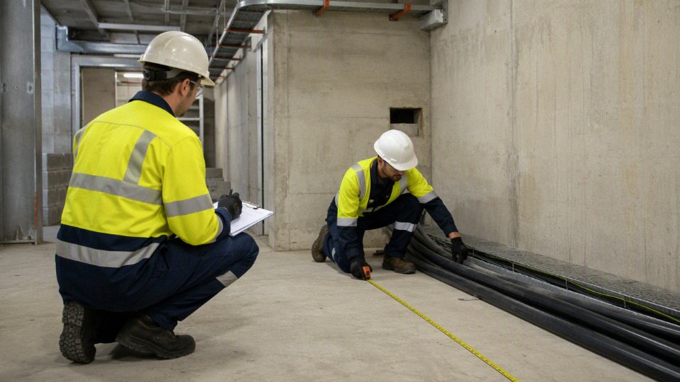
The trade-off is speed versus control. A fast pull with minimal setup saves crane time and labor on the day, but one damaged section can consume the saving many times over in fault location, excavation, replacement cable, and lost production. For long or high-value circuits, a pulling plan with calculated tension and sidewall pressure is not paperwork; it is cheap insurance.
Route preparation and heat management
Trenches, ducts, trays, tunnels, and joint bays need to be ready before the cable arrives at the route. The common mistake is checking that the path is physically open but not checking whether it is electrically and thermally suitable.
Route preparation should include:
- Cleanliness: Remove stones, scrap metal, tie wire, welding rod ends, concrete splatter, and sharp duct edges.
- Dryness where required: Some routes tolerate wet conditions by design; others do not. Joint bays and termination areas need much tighter moisture control than a buried duct bank.
- Mechanical protection: Confirm sand bedding, warning tapes, covers, duct class, tray supports, impact protection, and road-crossing sleeves.
- Heat dissipation: Review burial depth, soil thermal resistivity assumptions, duct fill, tray ventilation, and proximity to steam lines, furnaces, transformers, or other loaded cable circuits.
- Access: Make sure joint bays and terminations allow people to work cleanly, safely, and without bending the cable beyond its limit. A joint bay that only looks good on a drawing will punish the jointer later.
Spacing and grouping affect ampacity more than many buyers expect. Trefoil formation can reduce external magnetic fields and help balance single-core circuits, while flat formation may fit better on tray and sometimes cool better depending on spacing and airflow. Closer grouping saves civil space and tray width, but it increases mutual heating and may require derating. The preferred arrangement can flip when the constraint changes from trench width to load current, or from electromagnetic compatibility to thermal capacity.
For single-core cables, bonding design matters. Both-ends bonding is simple but can produce circulating current in metallic screens, which adds heat and reduces usable ampacity. Single-point bonding or cross-bonding can reduce those losses, but introduces sheath voltage considerations and requires correct link boxes, surge protection, labeling, and maintenance discipline. This is not an area for improvising in the field.
Termination and jointing workmanship
Medium voltage terminations and joints should be treated as controlled electrical assemblies, not as cable dressing work. The cable accessory has to manage electric stress, seal out moisture, maintain screen continuity where required, and survive thermal cycling for years.
Good jointing practice depends on:
- Trained jointers
- Use personnel trained on the accessory system being installed.
- Do not assume experience with low voltage glands transfers to medium voltage stress control.
- Clean stripping and preparation
- Remove semiconductor screens without scoring the insulation.
- Keep insulation surfaces clean, dry, and free from knife marks, fingerprints, carbon dust, and metallic particles.
- Correct screen cutback and stress control
- Follow the accessory instructions exactly for cutback distances and stress cone or stress tube placement.
- Small dimensional errors can concentrate the electric field at the wrong point.
- Moisture exclusion
- Control rain, condensation, dust, and humidity at the work face.
- Use tents, heaters, clean mats, and sealed consumables where conditions demand it. A joint made in a muddy trench with a wet glove is not the same joint shown in the accessory catalogue.
- Torque control and connector compatibility
- Use calibrated torque tools or approved shear-bolt connectors.
- Match lugs, ferrules, and connectors to conductor material, shape, size, and class. Copper, aluminum, round compacted, and sector conductors are not interchangeable details.
- Accessory compatibility
- Confirm voltage class, insulation diameter range, screen type, armor arrangement, sheath material, and indoor or outdoor service.
- Check creepage distance and pollution level for outdoor terminations, especially in coastal, mining, cement, chemical, and desert environments.
Commissioning tests before energization
Commissioning should prove that the installed circuit is continuous, correctly phased, adequately insulated, and free of gross installation damage. The exact test set must follow the cable standard, project specification, accessory manufacturer’s instructions, utility rules, and local safety requirements.
Typical commissioning checks include:
- Conductor continuity: Confirms the conductor path and helps identify crossed or open cores before energization.
- Phasing check: Essential where circuits are paralleled, tied into existing switchgear, or connected to rotating equipment.
- Insulation resistance test: Useful as a basic health and moisture indication, but not a complete proof of medium voltage insulation quality.
- Outer sheath integrity test: Especially important for buried or ducted cable with metallic screens, because sheath damage can lead to water ingress and screen corrosion.
- Very low frequency withstand testing: Commonly used for installed medium voltage cable where appropriate, but voltage level, duration, and suitability must be verified against the cable and accessory system.
- Partial discharge testing: Worth considering for critical feeders, long service-life assets, or networks where outage cost is high. It is more specialized than a simple withstand test and needs competent interpretation.
A cable can pass a basic continuity and insulation resistance check while still carrying a poor stress-control installation or a damaged sheath. That is why the test plan should match the consequence of failure. A small non-critical feeder in an accessible plant area may not justify the same diagnostic package as a main incomer feeding a process line that takes eight hours to restart.
Maintenance after the cable is in service
Maintenance is mostly about finding heating, moisture, discharge activity, loading changes, and mechanical damage before they become faults. Medium voltage cable is not inspected by opening it up; you inspect the system around it and trend the symptoms.
A practical maintenance program can include:
- Thermal scanning
- Inspect terminations, separable connectors, link boxes, switchgear cable boxes, and accessible joints under meaningful load.
- A scan at 15 percent load may look clean and still miss a loose connector that heats badly at peak production.
- Visual inspection of terminations
- Look for tracking, cracking, discoloration, oil or water marks, corrosion, animal damage, loose supports, and contamination buildup.
- Outdoor terminations deserve extra attention after storms, salt fog, dust events, or heavy industrial fallout.
- Sheath integrity checks
- Use where the system design and access allow. Trending sheath condition is particularly useful for buried circuits and routes with excavation risk.
- Partial discharge monitoring
- Apply where justified by asset criticality, failure history, or difficult access. It can catch accessory defects and insulation stress problems, but false confidence is dangerous if sensors, calibration, and interpretation are weak.
- Load review
- Compare actual current against design ampacity, seasonal ambient temperature, soil condition, duct occupancy, and operating mode.
- Plants change. A feeder designed for one mill line may later carry a larger motor, a VFD package, and a “temporary” bypass that has been in place for three summers.
- Records-based trend analysis
- Keep drum records, route drawings, joint locations, test results, thermal images, repair history, and loading data together.
- Maintenance crews cannot trend what procurement and construction never handed over.
Safety controls during installation, testing, and maintenance
Medium voltage work has no tolerance for casual habits. De-energization, lockout and tagout, proving dead, earthing, arc flash boundaries, test equipment ratings, induced-voltage control, and local electrical safety rules all have to be built into the method statement.
Minimum safety discipline should include:
- Isolate from all possible sources, including backfeeds, generators, UPS systems, capacitor banks, and parallel feeders.
- Apply lockout and tagout according to the site procedure, with clear ownership of keys and permits.
- Test before touch using approved, verified voltage detection equipment.
- Discharge and earth the circuit where required, including control of induced voltage on nearby or parallel cable runs.
- Use arc flash controls suited to the equipment and task, not just a generic PPE habit.
- Keep unauthorized trades out of joint bays, test zones, and switchgear fronts during high-potential or VLF testing.
- Verify every safety step against the current equipment manuals, applicable standards, utility requirements, and local regulations.
The engineering limits in this section stop being enough where the actual cable manual, accessory instruction, network rule, or site safety procedure gives a stricter requirement. In a well-run project, installation quality is not left to the last crew on site; it is specified, supervised, tested, recorded, and then maintained as part of the asset.
Common failures and prevention
Medium voltage cable failures are usually not “random cable problems”; they are the final result of electrical stress, heat, moisture, mechanical abuse, accessory workmanship, or a wrong application choice made months or years earlier. The cheapest failure to fix is the one removed at specification, handling, and commissioning stage, before the cable is buried, pulled into duct, or tied into a shutdown window.
Failure modes engineers should expect
| Failure mode | What normally drives it | What reduces the risk |
|---|---|---|
| Insulation breakdown | Electrical overstress, aging, overheating, contamination, manufacturing voids, water ingress, or partial discharge activity | Correct voltage rating, clean manufacturing, proper conductor sizing, temperature control, sheath integrity, and commissioning tests |
| Water treeing | Moisture-assisted degradation in polymeric insulation, especially where an electric field exists across wet insulation over long periods | Water-blocked designs where needed, intact outer sheath, sealed joints, good drainage, and avoiding flooded ducts where possible |
| Partial discharge | Localized discharge in voids, sharp interfaces, poor stress control zones, contaminated terminations, or defective joints | Correct accessory selection, trained jointing crews, clean work practices, PD testing where justified, and proper stress cone installation |
| Thermal overload | Excessive current, poor heat dissipation, high soil thermal resistivity, duct crowding, harmonic heating, or wrong derating | Ampacity calculation using actual installation conditions, load monitoring, thermal backfill, spacing, and allowance for future load growth |
| Mechanical damage | Crushing, overbending, excessive pulling tension, sheath cuts, armor damage, rodent attack, abrasion, or excavation strikes | Pulling plans, calibrated winches, rollers, bend-radius control, route protection, warning tape, marker posts, and post-install sheath testing |
| Accessory failure | Poor joint or termination workmanship, wrong dimensions, moisture, dirt, wrong kit, or inadequate stress control | Approved kits, measured cable dimensions, controlled jointing environment, torque control, and documented workmanship checks |
| Metallic screen or sheath problems | Undersized fault current path, corrosion, broken screen wires, poor bonding, circulating currents, or sheath voltage rise | Fault current verification, bonding design, corrosion protection, link box inspection, continuity testing, and sheath voltage checks |
| Chemical or environmental attack | Oil, solvents, acids, alkalis, salt spray, UV exposure, termites, fire exposure, or aggressive industrial washdown | Suitable sheath compound, armor choice, fire performance requirements, UV protection, termite barriers, and site-specific chemical review |
Insulation breakdown is the failure most people see on the incident report, but it is often the last domino. A small void, a damp joint interface, or a hot section in a duct bank can concentrate electric stress. That stress creates localized heating and discharge activity; the discharge carbonizes nearby material; carbonized material conducts better; the electric field becomes more concentrated; then the cable punctures. This is why a cable that passed a simple continuity check can still be carrying a serious defect.
Water treeing deserves separate attention on polymeric medium voltage cables. It is not the same as a puddle shorting two conductors. Moisture migrates into tiny defects or interfaces in the insulation while the electric field slowly changes the polymer structure into tree-like degraded paths. The practical lesson is plain: flooded ducts, damaged sheaths, unsealed ends left open during a rainy laydown period, and poor joint sealing can cut service life even when the cable energizes normally at first. Water blocking adds cost and diameter, but in wet ground, tunnels, coastal work, and plants with poor drainage, that extra cost is often cheaper than finding the fault under a concrete road three years later.
Partial discharge is an early warning mechanism, not a separate magic failure category. It happens where the local electric field exceeds the dielectric strength of a small gas pocket or weak interface, without immediately bridging the full insulation thickness. Terminations and joints are common suspects because field control depends on clean surfaces, correct stripping lengths, proper semicon removal, and the accessory matching the actual insulation diameter. I have seen crews do beautiful copper work and still ruin a termination with one dirty glove print on the insulation screen cutback.
Partial discharge is always visible from outside the cable before failure.False
Partial discharge usually occurs inside insulation systems, joints, or terminations and may leave no visible external sign until the defect has grown. Detection depends on suitable test methods, access points, noise conditions, and the sensitivity of the equipment used.
Thermal overload is less dramatic but just as expensive. A cable ampacity value is only valid for a defined installation: soil thermal resistivity, burial depth, duct arrangement, ambient temperature, conductor material, load profile, and grouping all matter. Put the same cable in a crowded duct bank beside other loaded circuits, then run nonlinear drives that increase harmonic heating, and the insulation temperature can creep beyond the design assumption. The trade-off is that upsizing conductor or improving the thermal environment costs money up front, while under-sizing saves purchase cost but spends it later as losses, aging, nuisance trips, or an unplanned outage. The “bigger cable is safer” rule stops holding when pulling tension, bend radius, tray loading, termination space, and short-circuit forces become the limiting factors.
Mechanical damage is often self-inflicted during installation. Prevention is basic, but basic does not mean optional:
- Check drum condition, end caps, and sheath damage before unloading.
- Use the manufacturer’s pulling tension and minimum bending radius, not a rule of thumb from a different cable type.
- Control sidewall pressure at bends; a long pull with one tight sweep can hurt the cable even if total pulling force looks acceptable.
- Keep rollers clean and aligned; a seized roller can shave a sheath quickly.
- Protect installed cable from scaffold legs, forklift forks, welding spatter, and temporary construction traffic.
- For direct-buried routes, record depth and route position accurately; future excavation is a common killer.
Accessory failure is the one that keeps showing up because joints and terminations are hand-built high-stress components. The cable may come from a controlled factory process, but the joint is assembled in a trench, substation bay, wind tower base, or dusty plant corner. Kit selection must match conductor size, insulation diameter, screen type, voltage class, and environmental exposure. Heat-shrink, cold-shrink, separable connectors, and premolded joints each have their place; the preferred choice changes with access, contamination risk, crew skill, energization schedule, and inspection requirements.
Metallic screens, sheaths, and armor need the same engineering attention as the conductor. They may have to carry earth fault current, limit touch voltage, provide shielding, and survive corrosion. Poor bonding can create circulating currents and heat; broken screen wires can compromise fault performance; sheath voltage limiters and link boxes need inspection, not just installation. In plants with salt air, fertilizer dust, acids, alkalis, oils, solvents, termites, UV exposure, or fire risk, the outer serving and protection system should be selected for the environment rather than copied from a generic data sheet.
A practical prevention hierarchy is:
- Specify the cable for the actual voltage system, grounding method, fault level, installation route, load profile, and environment.
- Buy from a manufacturer with controlled production and documented quality checks.
- Inspect drums, markings, end seals, and visible sheath condition on receipt.
- Store cable ends sealed and drums supported correctly, especially through wet seasons.
- Install with trained crews, proper tools, tension control, bend control, and clean accessory work.
- Test before energization using methods appropriate to the cable type, accessory system, and project standard.
- Monitor critical circuits with inspections, sheath checks, temperature review, PD assessment where justified, and maintenance records.
Repair makes sense for a young cable with a clear, isolated damage point and known history. Replacement becomes the more economical decision when an aged circuit has repeated partial discharge alarms, several old joints, evidence of water ingress, unknown installation records, or failures appearing in different locations. At that point the outage risk, fault-locating labor, civil work, emergency procurement, and production loss can exceed the price of a planned cable replacement during a controlled shutdown.
Frequently asked questions
What is a medium voltage cable used for?
Medium voltage cable is used to distribute power between substations, transformers, switchgear, generators, motors, and large electrical loads. In a plant, that might mean feeding a 6.6 kV compressor motor from a motor control center; in a utility network, it may connect a distribution substation to ring main units, pad-mounted transformers, or underground feeders.
Is 11 kV a medium voltage cable?
Yes. An 11 kV system is commonly treated as medium voltage in many industrial, commercial, mining, and utility distribution networks.
The exact cable designation depends on the standard and system voltage convention. Under IEC-style ratings, an 11 kV network is often served by cable classes such as 6/10 kV or 8.7/15 kV, depending on grounding, operating voltage, and local utility practice. Do not specify only “11 kV cable” on a purchase order; confirm the rated voltage format required by the project documents.
What is the difference between medium voltage cable and low voltage cable?
Medium voltage cable is not just a thicker low voltage cable. It has a higher voltage rating, a controlled insulation screen system, conductor screen, metallic screen or shield, stronger electric field management, different terminations and joints, and stricter routine and type testing expectations.
The practical difference shows up during installation. A low voltage lug can often be installed by a competent electrician with standard crimping tools. A medium voltage termination needs screen cutback control, stress control components, correct earthing of the metallic screen, clean workmanship, and usually a trained cable jointer. Small workmanship errors that would be harmless at 400 V can become partial discharge points at medium voltage.
Can medium voltage cable be buried underground?
Yes, but only when the cable construction and installation method suit the route. Direct burial, duct installation, cable trench, tunnel, and tray installation all impose different mechanical, moisture, heat dissipation, and repair-access conditions.
For underground use, confirm:
- Outer sheath material and chemical resistance
- Armor requirement, such as steel wire armor or steel tape armor where applicable
- Metallic screen design and fault current capacity
- Water-blocking construction if moisture migration is a concern
- Minimum bending radius during pulling
- Pulling tension limits
- Burial depth, warning tape, route markers, and mechanical protection
- Soil thermal resistivity and grouping with other loaded circuits
A cable that carries its rated current in free air may run too hot in a poorly backfilled duct bank. Thermal conditions are not a paperwork detail; they decide ampacity.
Is XLPE cable suitable for medium voltage?
Yes. XLPE insulation is widely used for modern medium voltage power cable because it offers good electrical strength, thermal performance, aging resistance, and mechanical robustness compared with older insulation systems.
XLPE is common in distribution networks, industrial feeders, renewable energy projects, mining power systems, and infrastructure circuits. The cable still needs the correct screens, sheath, armor, and test regime. “XLPE” alone does not define the cable; it only identifies the insulation material.
Should I choose copper or aluminum conductor?
Choose copper when compact size, higher conductivity, termination familiarity, or high short-circuit performance is the priority. Choose aluminum when weight and cost are more important and the installation has enough space for the larger conductor size.
The choice affects more than cable price:
- Ampacity and voltage drop
- Cable diameter and bending radius
- Drum length and handling weight
- Termination lug type and jointing practice
- Short-circuit withstand
- Tray, duct, and gland sizing
- Scrap value and theft risk in some regions
In practice, copper often wins in congested switchrooms and motor feeder terminations. Aluminum can be a sensible choice for long distribution feeders where space is available and the contractor is comfortable with the correct accessories.
What information is needed for a quotation?
A useful quotation needs enough detail to avoid substitution risk. Provide:
- Voltage rating, such as 6/10 kV, 8.7/15 kV, 12/20 kV, 18/30 kV, or 26/35 kV
- Applicable standard, for example IEC-based, utility-specific, or project-specific requirements
- Conductor material and size
- Number of cores
- Insulation type, normally XLPE for many modern projects
- Metallic screen type and required fault current capacity
- Armor type, if required
- Outer sheath material and color
- Required length and drum length preference
- Installation environment: indoor, outdoor, buried, duct, tray, tunnel, marine, mining, or corrosive area
- Fire, flame, smoke, or halogen requirements where specified
- Routine, sample, or special test requirements
- Packaging, marking, documentation, inspection, and delivery terms
If the buyer only sends “medium voltage cable, 11 kV, 1 km,” the supplier has to guess too much. That is how wrong sheath types, undersized screens, or incompatible accessories enter a project.
How long does medium voltage cable last?
Service life depends on design, manufacturing consistency, installation quality, electrical loading, soil or ambient temperature, moisture exposure, mechanical damage, and maintenance. Properly specified and correctly installed medium voltage cables are often expected to operate for decades, but there is no honest universal life number without the duty conditions.
The usual life-shortening factors are overheating, water ingress, poor jointing, partial discharge, cyclic overload, sheath damage, and aggressive soil chemistry. A cable in a clean indoor tray at steady load has a very different life profile from one in a wet duct bank with seasonal flooding and repeated emergency loading.
Can one cable design work for every country?
Not reliably. Standards, voltage designations, conductor preferences, fire rules, sheath markings, drum documentation, utility approval procedures, and accessory practices differ by market.
A cable acceptable for one IEC-based industrial project may still need changes for another buyer’s specification. Export projects should check language marking, test certificates, packing lists, inspection requirements, and whether local utilities accept the proposed construction before production starts.
Why buy from an experienced manufacturer?
Medium voltage cable projects need controlled manufacturing, consistent insulation extrusion, reliable screening, proper testing records, technical communication, export documentation, and repeat-batch capability. Price matters, but a cheap cable becomes expensive if it delays commissioning, fails acceptance testing, or cannot be matched later for project extensions.
For international buyers, manufacturer depth also matters. Shandong Jinda Special Cable Group Co., Ltd., established in 1987, operates five production bases in China with 470,000 m² of manufacturing space, more than 1,000 employees, and an integrated system covering R&D, production, sales, technical support, and after-sales service. That kind of structure is relevant when a project needs bulk supply, technical review, export coordination, and long-term repeat procurement rather than a one-off cable shipment.
Verify your project cable requirements
A medium voltage cable should never be purchased by voltage rating alone; it has to fit the electrical duty, installation environment, protection system, applicable standard, and expected service life. A cable marked 8.7/15 kV or 12/20 kV may still be wrong if the feeder is long, the fault level is high, the soil stays wet, the fire requirement is strict, or the termination system does not match the cable construction.
Before issuing a purchase order, freeze the main engineering inputs rather than leaving them to “supplier confirmation” after the price is agreed. That is where many expensive cable problems start: the commercial offer is approved, drum lengths are booked, and only then someone notices that the screen fault rating, sheath material, bending radius, or accessory interface was never properly checked.
Use this final verification list before requesting quotation or approving submittals:
- Voltage class and standard
- Rated voltage, such as 3.6/6 kV, 6/10 kV, 8.7/15 kV, 12/20 kV, 18/30 kV, or 26/35 kV
- Required standard, such as IEC project specifications or local utility requirements
- System maximum voltage and insulation coordination assumptions
- Electrical duty
- Continuous load current and expected load growth
- Emergency overload requirement, if allowed by the design
- Short-circuit current and fault duration
- System grounding method, because earth fault behavior affects screen, sheath, and accessory design
- Voltage drop limits on long feeders
- Cable construction
- Copper or aluminum conductor
- Conductor cross-section and stranding class
- XLPE insulation or other specified insulation system
- Metallic screen type and required screen fault capacity
- Armor requirement for mechanical protection
- Outer sheath material suitable for moisture, sunlight, chemicals, termites, abrasion, or flame performance
- Installation conditions
- Direct burial, duct, tray, tunnel, shaft, submarine approach, or overhead-to-underground transition
- Ambient temperature, soil thermal resistivity, grouping, and spacing
- Minimum bending radius and pulling tension
- Available installation space, especially in retrofit substations and old cable trenches
- Required drum lengths, joint locations, and site handling limits
- Safety, testing, and documentation
- Fire performance requirement for buildings, tunnels, metros, offshore platforms, or industrial plants
- Routine, type, or special test requirements
- Third-party inspection, witness testing, or mill certificates
- Terminations, joints, lugs, glands, and earthing kits
- Packing method, export marking, delivery schedule, and spare length allowance
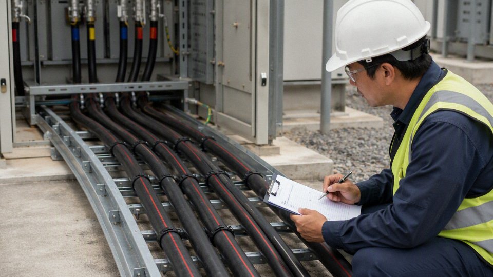
Identify the risks that cannot be negotiated away by a lower cable price. Wet soil can drive sheath selection and water-blocking requirements. Long feeder length can make voltage drop or charging current more important than the simple ampacity table. A high fault level can make the metallic screen or armor bonding arrangement a limiting item. Fire safety rules may narrow the acceptable sheath and flame performance options. Harsh chemicals, repeated movement, tight pulling routes, and strict inspection documentation all need to be stated before the offer is finalized, not after production has started.
There are useful trade-offs here. Aluminum conductor can reduce material cost and weight, but it normally needs a larger cross-section than copper for the same current and may affect termination size. Armor improves mechanical protection in burial or exposed industrial runs, but increases diameter, weight, bending effort, and freight cost. A heavier sheath or special fire performance can be the right decision in a tunnel or refinery, yet unnecessary for a controlled utility duct bank. The preferred choice flips with the route, fault level, installation method, and inspection regime.
Bring the cable manufacturer in early when the project still has room to adjust. The best timing is during:
- Tender specification review
- Cable sizing confirmation
- Accessory matching for joints and terminations
- Drum length and joint-position planning
- Export packing and lifting arrangement decisions
- Quality inspection and documentation preparation
Shandong Jinda Special Cable Group Co., Ltd. was established in 1987 and serves customers in more than 50 countries. With five production bases, integrated R&D, production, sales, technical support, and after-sales service, Jinda is structured for international cable projects, bulk procurement, and long-term supply programs rather than one-off catalogue selling.
Send your voltage class, applicable standard, route description, load current, short-circuit requirement, installation environment, accessories, quantity, documentation needs, and delivery schedule. Jinda’s technical and sales team can help verify the medium voltage cable specification and prepare a project-ready proposal aligned with the electrical duty, site conditions, and procurement requirements.