A medium voltage feeder is not the place to “buy close enough.” If the cable voltage class, insulation system, screen design, or termination method is wrong, the first sign may be nuisance trips, partial discharge, overheated joints, or a failed feeder during peak load. That turns into lost production, emergency labor, damaged switchgear, and replacement cable bought under pressure, so the better route is to understand what the cable is actually built to do before the purchase order is written.
A medium voltage power cable is an insulated cable used to transmit and distribute electrical power above low voltage levels, commonly from 3.6/6 kV to 26/35 kV under IEC practice and roughly 5 kV to 46 kV in North American systems. It typically includes a conductor, conductor screen, XLPE or similar insulation, insulation screen, metallic screen, and protective sheath.
The definition sounds simple, but the buying decision rarely is. A plant engineer looking at a 6.6 kV motor feeder, a utility buyer specifying 35 kV distribution cable, and an EPC team matching IEC 60502-2 or ICEA requirements are all dealing with “medium voltage cable,” yet the construction details, test expectations, installation risks, and commercial trade-offs can be very different.
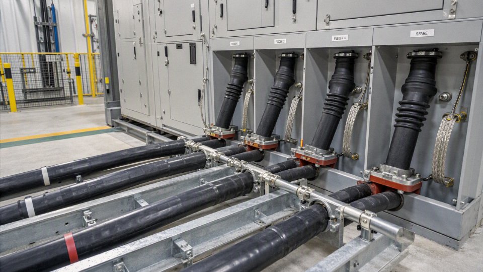
Voltage ratings and standards
Choose medium voltage cable by the system’s maximum voltage, grounding method, and governing standard, not by the nominal feeder voltage alone. A “15 kV cable” in one specification package may not be equal to another “15 kV cable” if the insulation level, shield design, test regime, or allowed fault duration is different.
Under IEC practice, voltage ratings are usually written as U0/U (Um):
- U0: rated power-frequency voltage between conductor and earth or metallic screen.
- U: rated power-frequency voltage between conductors.
- Um: highest system voltage for which the cable is intended.
So a cable marked 8.7/15 kV (17.5 kV) is not just a “15 kV cable.” It is designed around 8.7 kV conductor-to-earth, 15 kV conductor-to-conductor, and a maximum system voltage of 17.5 kV. That last value, Um, is where procurement mistakes often start. Plants buy around nominal line voltage, while the insulation system has to survive the actual maximum operating voltage plus credible overvoltage conditions defined by the network and standard.
Common IEC and North American classes overlap in the field, but they do not map one-to-one cleanly.
| IEC-style designation | Typical maximum system voltage reference | Rough North American class often compared | Procurement caution |
|---|---|---|---|
| 3.6/6 kV | 7.2 kV class systems, depending on standard | 5 kV / 8 kV | Check whether the plant uses 6 kV nominal or a higher maximum equipment voltage. |
| 6/10 kV | 12 kV class systems | 8 kV / 15 kV | Often confused in export projects; do not assume one regional label equals another. |
| 8.7/15 kV | 17.5 kV class systems | 15 kV | Very common industrial level, but insulation thickness and shield rules vary by standard. |
| 12/20 kV | 24 kV class systems | 25 kV | Confirm grounding and fault clearing time before treating it as a simple equivalent. |
| 18/30 kV | 36 kV class systems | 35 kV | Verify whether IEC 60502-2 or a higher-voltage standard/specification is required. |
| 26/35 kV | Around 40.5 kV class systems, where specified | 35 kV / 46 kV boundary area | Needs careful standard selection; some projects move into higher test and accessory requirements. |
The mechanism is straightforward but unforgiving. Cable insulation is stressed by electric field between the conductor and grounded metallic screen. If the phase-to-earth voltage rises during a ground fault, or if switching transients are severe, the stress is concentrated across the insulation wall and at accessories such as stress cones, separable connectors, and joints. A cable that looks adequate on nominal voltage can run for years in normal balance, then fail during a single-line-to-ground event because the insulation level was selected for a system that clears faults quickly and remains tightly referenced to ground.
Grounding method is one of the biggest reasons two projects with the same nominal voltage need different cable selections.
How grounding changes insulation selection
- Solidly grounded systems
These keep healthy phase-to-ground voltage relatively controlled during a ground fault. In North American practice, this often supports the use of lower insulation levels where fault clearing is fast and protection is coordinated. The buyer still has to confirm the required insulation percentage or level in the applicable ICEA, AEIC, utility, or project specification. - Low-resistance or high-resistance grounded systems
These are common in industrial plants because they limit ground-fault current and reduce arc-flash damage compared with a bolted fault. The trade-off is that the system may continue operating with one phase grounded for a controlled period. That can expose the unfaulted phases to elevated phase-to-ground voltage, so cable insulation level and accessory ratings need to match the permitted fault duration. Ungrounded systems
These can be attractive where continuity is valued, but they are hard on insulation if ground faults are not found quickly. Intermittent arcing ground faults can create overvoltages that are much higher than the steady-state number on the one-line diagram. In older plants, I have seen this made worse by weak ground detection and a maintenance habit of “letting it run until the next shutdown.”Impedance grounded systems
These sit between the extremes and must be reviewed from the actual grounding equipment data, not from a label. Grounding transformer size, neutral resistor value, protection settings, and allowed operating time under ground fault all influence cable insulation duty.
A useful buying rule is this: if the system can operate for an extended period with one phase grounded, do not select cable as though it were a promptly cleared solidly grounded system. The cost saved by shaving insulation level is small compared with the cost of excavating a failed feeder, replacing terminations, or losing a process line on a wet Sunday night.
Standards define more than the voltage number printed on the jacket. IEC 60502-2 is the common reference for extruded-insulation medium voltage power cables in many international projects, generally covering the medium voltage range up to the standard’s stated voltage limits. IEC 60840 becomes relevant for higher voltage cable systems and stricter system-level requirements. For North American utility and industrial work, buyers often see ICEA S-93-639, AEIC CS8, and utility specifications that add construction, qualification testing, partial discharge, shield, jacket, and manufacturing requirements. Accessories are their own discipline: IEEE 404 is commonly referenced for cable joints, while IEEE 48 is commonly referenced for terminations.
Two medium voltage cables with similar voltage labels may still be non-interchangeable.True
Voltage class alone does not define insulation thickness, shielding construction, qualification testing, accessory compatibility, installation assumptions, or utility acceptance requirements. These are governed by the selected standard and project specification.
This is where commercial substitutions get risky. A bidder may offer a cable that is “equivalent voltage,” but built under a different standard family. That substitution might be acceptable, or it might create a mismatch in:
- Insulation thickness and material requirements, especially between XLPE, TR-XLPE, EPR, and project-specific compounds.
- Conductor screen and insulation screen design, including bonded versus strippable screens and semiconductive layer requirements.
- Metallic screen or shield construction, such as copper tape, copper wire screen, concentric neutral, lead sheath, or corrugated metallic sheath.
- Partial discharge and routine test requirements, which can differ by standard and by utility specification.
- Jacket material and flame, oil, sunlight, water, termite, or abrasion resistance requirements.
- Accessory compatibility, since joints and terminations are designed around insulation diameter, screen type, conductor size, and stress-control geometry.
- Installation assumptions, including direct burial, duct bank, tray, tunnel, vertical riser, submarine section, or wet location.
The trade-off is procurement flexibility versus technical control. Allowing multiple equivalent standards can widen the supplier base and reduce lead time, which matters on a shutdown recovery job. The sacrifice is engineering certainty; every “equivalent” offer then needs a line-by-line compliance review. For a greenfield project with utility interconnection requirements, tight protection coordination, or long buried feeders, I would rather specify the standard and required documents tightly than sort out ambiguity after cable production has started.
A practical request for quotation should state the following items clearly:
- Rated voltage designation
Use the correct IEC notation, such as 8.7/15 kV (17.5 kV), or the required North American class, such as 15 kV, 25 kV, or 35 kV. Maximum system voltage
Do not leave the supplier to infer this from the nominal line voltage.System grounding method
State whether the system is solidly grounded, resistance grounded, ungrounded, or impedance grounded, and include allowed ground-fault clearing time if known.Applicable cable standard
Name the governing standard, such as IEC 60502-2, IEC 60840 where applicable, ICEA, AEIC, or the project utility specification.Accessory standards and interface requirements
Identify required compliance for joints, terminations, separable connectors, and test plugs where relevant, including IEEE 404 or IEEE 48 if they apply.Required test documents
Ask for routine test reports, type test or qualification evidence where required, partial discharge test records if specified, dimensional data, and material compliance documents.Installation condition and environment
Include burial depth, duct or tray installation, wet location exposure, ambient temperature range, chemical exposure, fire performance, and pulling route constraints.Certification and approval needs
State whether the cable must meet a named utility approval, third-party certification, national grid requirement, or project owner specification.
This guidance stops holding when the project owner has a binding utility standard or national code that already dictates the cable class, insulation level, and accessory system. In that case, the buyer’s job is not to reinterpret voltage rating theory; it is to make sure every supplier deviation is visible before award, especially the quiet ones buried in shield construction, test certificates, and termination compatibility.
Core cable construction
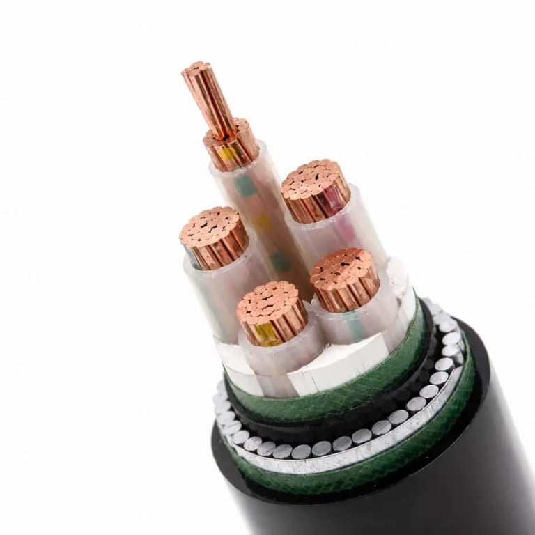
A medium voltage power cable is not just an insulated conductor with a thick jacket; it is a controlled electric-field device built in layers. The conductor, screens, insulation, metallic shield, moisture protection, armor, and sheath all affect ampacity, fault behavior, installation risk, service life, and purchase price.
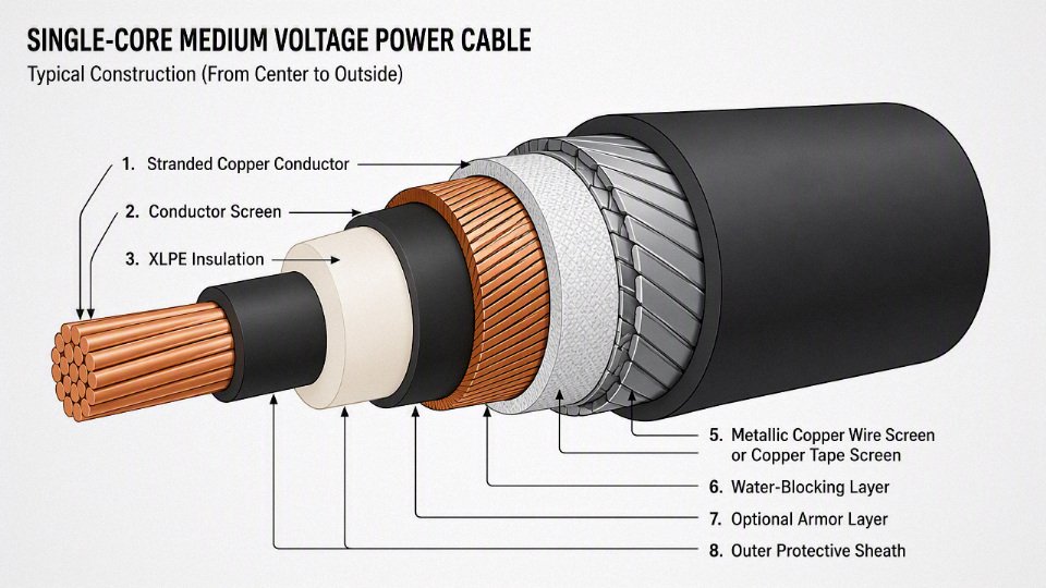
Conductor: copper, aluminum, shape, and flexibility
The conductor is the current path, but its material and geometry also influence pulling tension, termination size, losses, and procurement cost. Most medium voltage cables use stranded conductors rather than solid conductors, because stranding improves bendability and makes large cross-sections practical to manufacture and install.
Common conductor choices include:
- Stranded copper: higher conductivity per unit area, smaller diameter for the same current, better termination familiarity in many plants. It costs more and is heavier, which matters on long tray runs, vertical shafts, offshore lifts, and export packing.
- Stranded aluminum: lower material cost and lighter weight, useful for feeders, renewables, utilities, and large projects where kilometer quantities dominate the budget. It needs proper lugs, oxide control, and torque discipline; a lazy termination crew can erase the saving quickly.
- Compacted conductors: stranded conductors compressed to reduce diameter and smooth the surface. This helps cable size, screen uniformity, and pulling through ducts, though the conductor is less flexible than a loose-stranded equivalent.
- Sector-shaped conductors: used mainly in multi-core cables to reduce overall diameter by nesting the cores efficiently. They can be attractive where tray space is tight, but accessories and bending behavior need checking because the geometry is less forgiving than round cores.
- Class-based flexibility: standards define conductor classes for flexibility. A normal stranded power conductor is not the same thing as a flexible trailing or reeling cable conductor; if the cable will move in service, the conductor class and insulation system must be selected for dynamic duty, not just voltage and ampacity.
The practical trade-off is simple: copper often buys compactness and easier terminations; aluminum buys lower weight and cost. The preferred choice flips when civil constraints, pulling limits, or installed accessory labor outweigh conductor metal price.
Semiconductive conductor screen
The conductor screen is a semiconductive layer applied over the conductor to smooth the electric field. Without it, the electric stress would concentrate around individual strand edges, small air gaps, and surface irregularities. At medium voltage, those tiny high-stress points are where partial discharge can start, especially if manufacturing cleanliness or extrusion bonding is poor.
In modern MV cables, the conductor screen is normally extruded and bonded as part of a triple-extrusion process with the insulation and insulation screen. That process is not just a factory preference; it reduces contamination and interfaces, which are two enemies of dielectric life. If a buyer is comparing low-priced offers, this is one place to ask about production method, online monitoring, and routine electrical testing rather than judging by insulation thickness alone.
Insulation: XLPE and EPR
XLPE is widely used because it combines strong dielectric performance, good thermal capability, broad manufacturing availability, and a well-developed accessory ecosystem. In many industrial and utility applications, XLPE gives a good balance of ampacity, cost, diameter, and long-term stability when the cable is manufactured, stored, installed, and terminated correctly.
EPR is still important. It is generally more flexible and can be more forgiving in certain wet, mobile, or high-vibration environments, depending on formulation and standard. It may have a larger diameter or different loss characteristics than XLPE, and it is not always the lowest-cost option. For plant distribution feeders in trays and ducts, XLPE is usually the default; for flexible service, mining, shipboard, temporary power, or harsh handling, EPR deserves a serious look.
The insulation material alone does not define cable quality.True
MV cable life depends on the full insulation system: conductor screen, insulation cleanliness, insulation screen compatibility, moisture protection, factory testing, accessories, and installation workmanship.
Insulation screen and controlled electric field
The insulation screen is another semiconductive layer, placed over the insulation. Its job is to maintain a controlled radial electric field and provide a uniform interface to the metallic shield. This layer must be compatible with the insulation and shield system; poor adhesion, stripping behavior, or contamination can make jointing and terminating harder and can raise partial-discharge risk.
There are two practical issues buyers often miss:
- Strippability: Termination crews need the screen to strip cleanly without gouging the insulation. A cable that looks fine on a datasheet can cost hours per termination if the screen is difficult to remove.
- Accessory compatibility: Premolded joints, cold-shrink terminations, heat-shrink systems, and separable connectors depend on correct screen dimensions and surface preparation. Do not assume every accessory fits every cable construction.
Metallic screens and shields are part of the electrical design
The metallic shield is not an optional accessory; it is part of the cable’s electrical safety and fault-management system. It provides a grounded path around the insulation system, helps control touch voltage, supports electromagnetic control, and may carry earth-fault current until protection operates. If the shield is undersized, poorly grounded, or interrupted at joints, the cable system can become unsafe even when the conductor and insulation are correctly rated.
Common metallic shielding arrangements include:
| Shield or sheath type | Where it is commonly used | Main engineering role | Watch point |
|---|---|---|---|
| Copper tape screen | Industrial MV feeders, many IEC-type cables | Electric field control and grounding path | Limited fault-current capacity unless designed for it |
| Copper wire screen | Utility and industrial feeders | Better fault-current capability and flexibility than tape in many designs | Wire area and bonding method must match protection study |
| Concentric neutral | Common in North American distribution | Neutral return and shielding function | Neutral corrosion and grounding practice are critical |
| Lead sheath | Wet, chemical, refinery, underground, or legacy specifications | Excellent moisture barrier and chemical resistance | Heavy, costly, handling and environmental controls matter |
| Aluminum laminate or metallic moisture barrier | Longitudinal water protection in wet ducts or buried routes | Radial moisture blocking with lower weight than lead | Bending radius and sheath damage control are important |
Shield grounding is not a paperwork detail. Single-point bonding, both-end bonding, cross-bonding, and sheath voltage limiters all have consequences for circulating current, sheath losses, induced voltage, and personnel safety. The correct method depends on circuit length, load current, fault level, installation layout, and local utility rules.
Water-blocking and moisture barriers
Water does not need a dramatic flood to damage a medium voltage cable. A cracked duct, sweating manhole, damaged outer sheath, or poor gland can introduce moisture that migrates along the cable and into joints. Once water reaches insulation interfaces, accessories, or metallic screens, aging and corrosion accelerate.
Water protection is usually built in layers:
- Longitudinal water-blocking tapes: swell when wet and restrict water travel along the cable.
- Water-swellable powders: fill small voids and help block migration.
- Swelling yarns: used around screens, armors, or conductor areas depending on design.
- Metallic moisture barriers: lead sheath, aluminum laminate, or other bonded barriers for stronger radial moisture protection.
The trade-off is cost and handling. A fully blocked cable with a metallic barrier is usually better for wet ducts, direct burial, coastal sites, and poorly drained trenches, but it can be stiffer, heavier, and more expensive. In dry indoor tray service, that extra construction may be unnecessary unless the plant has washdown, condensation, or chemical exposure that the electrical specification forgot to mention.
Armor and mechanical protection
Armor protects against crushing, impact, rodent damage, and installation abuse. In practice, armor selection is where electrical and mechanical thinking must meet.
Typical options are:
- Steel wire armor: strong mechanical protection, often used on multi-core cables and direct-buried industrial feeders.
- Steel tape armor: good crush protection, common in some regional specifications and underground applications.
- Aluminum wire armor: used for single-core AC cables where nonmagnetic armor is needed.
- Nonmagnetic armor systems: selected to avoid circulating magnetic losses and heating around single-core AC circuits.
For single-core AC cables, magnetic steel armor can heat badly because the alternating magnetic field induces losses in the armor. That is not a minor efficiency issue; it can reduce ampacity and create hot spots. If a project uses single-core cables in trefoil or flat formation, armor material, bonding, and installation spacing need review together.
Outer sheath compounds
The outer sheath is the cable’s first defense against the plant environment. PVC is common and economical, with decent flame behavior depending on formulation. PE is tougher and moisture-resistant, often preferred for underground service, but flame performance must be checked where cables enter buildings or tunnels.
Other sheath compounds are selected for specific hazards:
- LSZH compounds: reduce smoke and halogen acid gas in occupied areas, tunnels, transit systems, and enclosed substations.
- Flame-retardant compounds: used where cable fire propagation is a design concern.
- Oil-resistant compounds: needed near lubricants, hydrocarbons, rolling mills, ports, and some process plants.
- Termite-resistant compounds: relevant for buried routes in affected regions.
- Sunlight-resistant materials: required for outdoor tray, rooftop, solar, and exposed substation runs.
The outer sheath cannot compensate for a wrong electrical design, but it can decide whether a correct electrical design survives the site. Before freezing the cable construction, check the actual route: duct bank or tray, wet or dry, indoor or outdoor, rodent risk, fire zone, chemical exposure, pulling length, bend radius, and available jointing skill. That route survey is often where the cheapest technically acceptable cable and the lowest installed-cost cable stop being the same thing.
Applications and installation environments
Medium voltage power cables are specified wherever power must be moved beyond low-voltage plant distribution but below transmission-class systems: utility feeders, plant substations, renewable collection circuits, transportation infrastructure, and heavy industrial loads. The electrical rating may look simple on a datasheet, but the installation environment often decides the actual ampacity, service life, jacket choice, shielding arrangement, and termination method.
Utility distribution and network feeders
Utilities use medium voltage cables for underground distribution feeders, substation exits, ring main systems, urban networks, and overhead-to-underground transitions. A typical feeder leaving a substation may run through ducts, manholes, road crossings, and pad-mounted switchgear before branching into distribution transformers. The cable has to tolerate load cycling, fault current duty, moisture exposure in handholes, and repeated switching transients from the network.
Ring main systems put a different kind of pressure on the cable and accessories. The cable may not carry full load all the time, but it must remain reliable through sectionalizing, back-feeding, and future expansion. In practice, the weakest part of these systems is often not the factory-made cable; it is a poorly prepared termination, a contaminated joint interface, or a bend forced into a cramped switchgear cable box.
Overhead-to-underground transitions deserve special attention. The cable moves from sun, wind, and surge exposure at the pole into ducts or direct burial below grade. That transition zone commonly needs surge protection coordination, mechanical guarding, UV-resistant exposed sections, water-blocking where specified, and enough slack for termination work without violating bending radius.
Industrial plants and large motor feeders
Steel plants, cement works, chemical plants, refineries, water treatment facilities, and large manufacturing campuses use medium voltage cables to feed unit substations, motor control centers, compressors, mills, kilns, pumps, fans, and large drives. These sites are rarely gentle. Cable routes pass near hot surfaces, vibrating structures, oil mist, washdown areas, dust buildup, corrosive vapors, and equipment that maintenance crews will eventually drag across a tray whether the design engineer likes it or not.
Large motor feeders are a common case where selection goes beyond voltage and conductor size. Starting current, variable frequency drive output, harmonic heating, grounding method, shield bonding, and fault clearing time all affect cable stress. A pump feeder in a water plant may mainly need wet-location performance and good terminations. A feeder to a rolling mill motor may need tougher mechanical protection, vibration control at the termination, and careful routing away from heat and impact zones.
Chemical plants and refineries add another layer: jacket compatibility. Hydrocarbons, solvents, acids, alkalis, and cleaning chemicals can attack materials differently. A jacket that is acceptable in a dry electrical room may not be the right choice in a pipe rack where condensate and process residue collect around cable cleats.
Renewable energy and distributed generation
Solar farms, wind farms, battery energy storage plants, inverter stations, collection circuits, and step-up transformer connections use medium voltage cables heavily. The design challenge is usually not just one long feeder; it is many repeated cable runs spread over a wide site, often with high exposure to soil variation, water, UV, and installation handling.
In solar plants, collection circuits may run from inverter stations to medium voltage switchgear or step-up transformers. Soil thermal resistivity can vary sharply between compacted access roads, dry sandy areas, and wetter low spots. If ampacity was calculated using optimistic soil data, a cable that looked properly sized on paper may run hotter than expected during peak generation.
Wind farms bring long collection circuits, terrain changes, and repeated terminations in turbine towers or pad-mounted equipment. Energy storage plants bring high cycling duty. The cable may heat and cool daily as the system charges and discharges, so accessory workmanship, shield grounding, and thermal expansion management become more visible over time.
Two medium voltage cables with the same voltage rating and conductor size can deliver different continuous current in service.True
Ampacity depends on installation conditions such as soil thermal resistivity, ambient temperature, grouping, burial depth, duct fill, solar exposure, and heat dissipation around trays or tunnels, not only on conductor cross-section.
Mining, tunneling, and mobile heavy equipment
Mining and tunneling applications are a separate class in practical terms. Cables may be dragged, reeled, run through wet headings, exposed to rock impact, crushed under mobile equipment, or connected to portable substations, drills, conveyors, pumps, and tunnel boring systems. Flexibility, abrasion resistance, water resistance, tear strength, and visible jacket damage inspection can matter as much as electrical rating.
A fixed medium voltage feeder in a cable trench is not the same product as a trailing cable feeding mobile mining equipment. The trade-off is straightforward: a flexible, mechanically robust cable is easier to handle and more tolerant of movement, but it is usually more expensive, may have different ampacity assumptions, and needs closer inspection for jacket damage and conductor fatigue. The preferred choice flips when the cable is no longer static; once regular movement, dragging, or reeling enters the duty cycle, a standard fixed-installation cable becomes a bad economy.
Transport, infrastructure, and mission-critical facilities
Airports, ports, rail transit systems, metro networks, highway tunnels, hospitals, data centers, and district energy systems use medium voltage cables because loads are concentrated and continuity is expensive to lose. These projects often impose fire performance, smoke emission, circuit integrity, routing separation, and redundancy requirements through project specifications or local codes.
Rail and metro installations can involve vibration, stray current concerns, restricted tunnels, and strict fire behavior requirements. Airports and ports often combine long outdoor routes with high-power substations and sensitive uptime requirements. Hospitals and data centers place more weight on reliability, maintainability, testing access, and coordination with emergency power systems than on first purchase price alone.
Installation environments and what they change
| Installation environment | What usually matters most | Common selection pressure |
|---|---|---|
| Direct burial | Soil thermal resistivity, moisture, rocks, rodents, termites, burial depth | Jacket toughness, water blocking, mechanical protection, derating accuracy |
| Duct banks and conduits | Heat buildup, duct fill, pulling tension, sidewall pressure | Ampacity derating, pulling lubricant, bend radius, route planning |
| Cable trays | Air circulation, grouping, fire exposure, mechanical damage | Flame performance, tray rating, spacing, cleats or supports |
| Tunnels and galleries | Fire load, smoke, access, ventilation, grouping | Low-smoke materials where required, support spacing, inspection access |
| Riser shafts | Vertical support, flame spread, termination access | Cleating, pulling method, fire stopping, minimum bend control |
| Trenches | Drainage, rodents, shared services, cover plates | Moisture protection, separation from heat sources, maintenance access |
| Wet or underwater locations | Long-term water exposure, pressure, sheath integrity | Water-resistant construction, verified accessories, sheath testing |
| Exposed outdoor routing | UV, solar heating, wind, ice, mechanical impact | UV-resistant jacket, sunlight derating, guards, secure supports |
Thermal conditions are where many procurement mistakes hide. Ambient temperature, soil thermal resistivity, cable grouping, duct arrangement, burial depth, and solar radiation all change how quickly heat leaves the conductor. Higher conductor temperature accelerates insulation aging, and in XLPE-insulated medium voltage cables the permissible operating, emergency, and short-circuit temperatures must still be checked against the applicable standard and cable design.
The mechanism is simple but unforgiving: current produces heat in the conductor, shields, armor, and metallic screens; the installation either removes that heat or traps it. A single cable in moist soil can perform very differently from the same cable in a crowded duct bank under dry compacted backfill. Same voltage rating, same conductor size, and same catalogue page do not guarantee the same field capacity.
Mechanical and environmental details also change the selection. Pulling route geometry affects maximum pulling tension and sidewall pressure at bends. Chemical exposure pushes jacket material choice. Rodents and termites may justify armor or protective ducts depending on local practice. Vibration near motors, transformers, rail equipment, and pumps affects support spacing and termination strain relief. Fire requirements may drive low-smoke, flame-retardant, or circuit-integrity constructions, but those choices can affect flexibility, cost, and availability.
Termination quality is the other big divider between paper design and operating reliability. Shield cutback, insulation cleanliness, stress control placement, lug crimping, moisture sealing, and phase spacing all affect electric field distribution. A well-made cable installed with poor terminations will not behave like a good system. The main conclusion stops holding when accessories, installation workmanship, or site thermal data are unknown; at that point, cable selection should be tied to route drawings, load profile, installation method, accessory type, and the project standard rather than voltage and conductor size alone.
Electrical sizing and performance
Correct medium voltage cable sizing is not just “pick the next larger conductor.” It is a thermal, voltage, fault-duty, installation, and commercial calculation tied to the whole cable system: conductor, insulation, screens, bonding, joints, terminations, route, protection settings, and expected loading over time. A cable that is electrically adequate on paper can still be the wrong cable if it cannot be pulled, terminated, cooled, bonded, or protected in the actual installation.
Ampacity is a heat balance, not a catalog number
Ampacity is the maximum current a cable can carry without exceeding the permitted conductor temperature under stated conditions. For XLPE-insulated medium voltage cables, a typical design reference is 90°C maximum conductor temperature in normal operation, with emergency overload and short-circuit limits only allowed when the applicable standard, cable design, and protection study permit them. Those temperature limits do not mean the cable will carry the same current in every trench, duct bank, tray, or tunnel.
The mechanism is straightforward: current creates I²R heat in the conductor; dielectric losses, screen losses, sheath losses, and armor losses may add more heat; that heat must escape through insulation, metallic layers, bedding, jacket, air, duct, concrete, backfill, or soil. Change the surrounding thermal resistance and the same cable runs hotter at the same current.
Key ampacity inputs include:
- Conductor material and size
Copper gives lower resistance than aluminum for the same cross-section, so it generally carries more current and has lower losses. Aluminum is lighter and often cheaper, but terminations, lugs, oxide control, and pulling practices need proper attention. Insulation temperature rating
XLPE and EPR systems are usually selected for medium voltage service because they tolerate higher operating temperatures than older thermoplastic systems. The rating still depends on the governing standard and manufacturer’s design.Installation method
A cable in free air on a ventilated tray cools very differently from a cable in a concrete-encased duct bank. Buried direct cables depend heavily on soil thermal resistivity, moisture, burial depth, and spacing.Ambient temperature and soil condition
A summer equipment yard with sun-loaded trays is not the same as a shaded cable cellar. Dry sandy soil can be a poor heat sink; wet native soil may perform better, until seasonal drying changes the assumption.Grouping and spacing
Several loaded circuits in one tray or duct bank heat each other. This is where optimistic early layouts cause trouble: the electrical schedule says one thing, the civil trench detail quietly removes 15–30% of usable ampacity, give or take, depending on the geometry and soil data.Permissible conductor temperature
Running closer to the maximum rating improves current capacity but accelerates thermal aging and leaves less margin for overloads, harmonics, and unexpected grouping. In practice, owners with hard-to-access feeders often buy some thermal margin because one failed joint in a duct bank can be far more expensive than the conductor upsizing they debated for weeks.
A medium voltage cable has one universal ampacity based only on conductor size.False
Ampacity depends on conductor material, insulation rating, installation method, ambient temperature, soil thermal resistivity, grouping, bonding arrangement, and applicable derating factors.
Voltage drop and starting performance
Voltage drop becomes critical on long feeders, wind or solar collection circuits, mine conveyors, water pumping stations, port equipment, and remote substations. A cable may pass the ampacity check but still cause unacceptable voltage at the load end under running or starting conditions.
For steady loads, voltage drop is driven by current, route length, conductor resistance, reactance, power factor, and system voltage. At medium voltage, the percentage drop is often more manageable than at low voltage, but long runs and high currents still matter. For motor feeders, the difficult case is usually starting: locked-rotor current can be several times running current, and the voltage dip can reduce starting torque just when the motor needs it most. Soft starters and variable frequency drives change the profile, but they bring their own harmonic and insulation coordination questions.
Typical cases that deserve separate voltage checks:
- Long radial feeders feeding pump houses, crushers, or remote process buildings.
- Large motor starting circuits, especially direct-on-line starts or weak utility supplies.
- Renewable collection systems, where current direction and voltage rise may change with generation output.
- Sensitive loads, including drives, control power transformers, large UPS inputs, and equipment with undervoltage trip settings.
- Temporary or staged operation, where a feeder may initially serve light load but later pick up additional transformers or motor loads.
The trade-off is that reducing voltage drop often pushes the design toward a larger conductor, higher voltage class, shorter route, parallel cables, or local transformation. Larger conductors reduce resistance, but they also increase bending stiffness, termination size, cable tray load, reel weight, and sometimes installation risk. The preferred answer flips when voltage performance is the limiting condition rather than heating, especially on long feeders with modest continuous current.
Short-circuit withstand is a system protection question
Short-circuit rating is not only about the main conductor surviving a fault. The metallic screen, copper tape, copper wire screen, concentric neutral, lead sheath, armor, and bonding leads may also have to carry earth-fault current until the protective device clears. If the screen is undersized for the earth-fault duty, the cable can be damaged even when the phase conductor looks adequate.
Short-circuit checks normally cover:
| Element checked | What must be verified | Practical issue |
|---|---|---|
| Phase conductor | Thermal withstand for fault current and duration | Based on initial conductor temperature, material, cross-section, and clearing time |
| Metallic screen or concentric neutral | Earth-fault current capacity | Often the weak point in resistance-grounded or solidly grounded systems |
| Armor, if used | Whether it is permitted to contribute to fault return path | Must be supported by standard, design, and bonding practice; do not assume |
| Joints and terminations | Fault current path and thermal stress | Accessories must match the cable construction and fault duty |
| Bonding leads and link boxes | Current rating and mechanical integrity | Small bonding conductors can become the bottleneck |
| Protection clearing time | Actual relay, breaker, fuse, and backup clearing time | A 0.2-second assumption is dangerous if backup clearing is closer to 1 second |
Short-circuit withstand is calculated against the system fault level and clearing time, not against a vague “medium voltage” label. A cable selected for a plant with current-limiting fuses may not be acceptable after a switchgear upgrade that increases available fault current or changes relay timing. Verify against the current protection study, applicable standard, and cable supplier data; do not reuse an old feeder size simply because it worked before.
Load profile, future capacity, and harmonics
Continuous load is the easy case. The harder work is deciding what the cable will actually see over 20 or 30 years: cyclic production, seasonal peaks, standby feeders, emergency ties, future motors, transformer additions, and non-linear loads.
A practical sizing review should separate:
- Continuous operating current
The normal production or service load the cable carries for long periods. Cyclic load
Loads that heat the cable during peaks and cool during idle periods. Thermal modeling may justify a different result than a simple continuous rating, but only when the duty cycle is well known.Emergency overload
Some XLPE cable systems may permit emergency operation above normal temperature limits, with values such as 130°C sometimes referenced in applicable designs. That is not free capacity; it consumes aging margin and must be allowed by the project specification, standard, accessories, and operator policy.Future expansion
The cheapest time to add copper or aluminum is often before the trench is backfilled. The cheapest time to avoid an oversized cable is before procurement locks in reels that require special handling.Diversity
Not every connected load runs at full load together. Diversity can prevent oversizing, but it needs operational agreement, not spreadsheet optimism.Harmonics
Drives, rectifiers, arc furnaces, and large power electronics can increase heating through RMS current, skin effect, proximity effect, and losses in metallic screens or sheaths. Harmonic filters, phase arrangement, and neutral or screen design may become part of the cable decision.
The boundary here is data quality. If the plant cannot state duty cycle, expansion plans, and harmonic content with reasonable confidence, the sizing result should be treated as preliminary and given margin or verified through a power system study.
Sheath bonding and circulating current in single-core systems
Single-core medium voltage cables need special care because magnetic fields from the phase conductors induce voltage in metallic screens and sheaths. If both ends are bonded, circulating current can flow in the screen. That current creates extra heat, reduces ampacity, wastes energy, and can surprise maintenance crews who expected the screen to be only a grounding component.
Common bonding arrangements include:
- Single-point bonding
The screen is grounded at one end only, preventing circulating current. The trade-off is standing sheath voltage at the open end, so route length, touch voltage limits, and sheath voltage limiters must be checked. Both-end bonding
Simple and robust from a grounding perspective, but circulating screen current can be significant on long or heavily loaded circuits. It is common where lengths are short or losses are acceptable.Cross bonding
Used on longer runs, usually split into sections so induced voltages cancel across phases. It reduces sheath losses but requires correct phase transposition, link boxes, testing discipline, and good installation records. One swapped link can undo the benefit.Sheath voltage limiters
Installed to control transient overvoltages on specially bonded systems. Their rating and location matter; they are not decorative accessories.
In plant-floor terms, bonding is where electrical design meets maintenance reality. Link boxes get flooded, labels fade, and someone may reconnect screens “the safe-looking way” after a shutdown. Good drawings, stainless tags, and commissioning tests are cheap compared with chasing unexplained hot cables in a tray.
Losses and lifecycle cost
A larger conductor costs more to buy, but it can reduce power losses for every hour the feeder is energized. For high-load, high-hour circuits, the economics can favor upsizing even when the smaller cable satisfies ampacity and voltage drop. The calculation is based on I²R losses, operating hours, load factor, electricity cost, expected service life, and the added cost of cable, accessories, supports, pulling labor, and space.
This is not a universal argument for oversizing. A lightly loaded standby feeder may never recover the added purchase cost. A larger single-core cable may require bigger glands, longer bend radii, larger termination enclosures, heavier tray supports, larger pulling equipment, and more difficult drum handling. Bigger is not automatically safer; once installation practicality, termination fit, screen fault rating, tray fill, and pulling tension become limiting factors, upsizing can create new failure modes.
The best procurement comparison is not only price per meter. Ask for the full installed and operated cost: cable, joints, terminations, lugs, glands, pulling method, civil space, losses, expected loading, outage risk, and spare strategy. That is usually where the apparently cheap option and the maintainable option separate.
Data needed for accurate cable sizing
Before a manufacturer, consultant, or plant engineer can size a medium voltage cable responsibly, the following information should be fixed or clearly stated as an assumption:
- Load current, power factor, and duty cycle.
- System voltage and voltage tolerance at the load.
- Earthing or grounding method.
- Available fault level and protection clearing time.
- Route length, including vertical risers and termination tails.
- Installation method: tray, ladder, conduit, duct bank, direct buried, tunnel, or mixed route.
- Ambient air temperature, soil temperature, soil thermal resistivity, burial depth, and backfill type where relevant.
- Number of circuits grouped together and their spacing.
- Single-core or three-core construction.
- Sheath bonding method and screen fault-current duty.
- Harmonic content or major non-linear loads.
- Required standards and project specifications, such as IEC 60502-2, IEC 60840 where applicable, ICEA, AEIC, IEEE accessory standards, or utility-specific requirements.
- Future expansion allowance and any emergency operating philosophy.
If any of these are unknown, the sizing can still be estimated, but the estimate should be marked as conditional. On medium voltage projects, that honesty saves money: it prevents buying a cable that is thermally correct for a clean drawing and wrong for the trench, switchgear room, and maintenance crew that actually have to live with it.
Insulation and sheath materials
Material selection in a medium voltage cable is not a cosmetic specification; it changes dielectric life, installation handling, fire behavior, environmental survival, and the buying price. For most projects, XLPE insulation with a PVC, PE/HDPE, or LSZH sheath covers the normal procurement range, while EPR insulation and special sheath compounds earn their cost where flexibility, moisture tolerance, confined-space safety, or harsh chemicals justify it.
XLPE vs EPR insulation
XLPE is the dominant insulation choice in many IEC and utility medium voltage projects because it gives high dielectric strength, low dielectric loss, good thermal aging performance, and a widely understood manufacturing base. In typical XLPE medium voltage cable designs, the maximum conductor temperature is commonly specified around 90°C in normal operation, with higher emergency and short-circuit limits only when permitted by the applicable standard and cable design. That does not mean every XLPE cable can be loaded to the same current; conductor size, screen bonding, laying method, soil thermal resistivity, grouping, and ambient temperature still decide the ampacity.
EPR has a different character. It is usually more flexible, more forgiving during pulling and bending, and often valued where the cable sees movement, vibration, tight routing, mining-type duty, portable substations, shipyard-like handling, or damp service conditions. EPR also has a reputation for good moisture tolerance, but buyers should not turn that into a blanket excuse to ignore water blocking, metallic screen protection, or sheath integrity. Water travels through bad joints and damaged sheaths faster than most office calculations admit.
The trade-off is cost, loss, and market availability. XLPE is usually more economical and easier to source in large quantities across standard voltage ratings. EPR may carry a price premium and, depending on formulation, can have higher dielectric losses than XLPE. The preferred choice flips when installation abuse, bending radius, cyclic handling, or wet operating conditions are more threatening than the incremental material cost.
Termination handling also differs. XLPE is relatively firm and dimensionally stable, which helps with screen stripping and stress-control accessory fitting when crews use proper tools. EPR’s elasticity can be useful in tight spaces but may require more care during insulation preparation. A jointer using a dull knife, wrong screen-stripping depth, or contaminated gloves can ruin either system; insulation brand names do not save poor workmanship.
Why semiconductive compound and extrusion quality matter
The insulation material gets most of the attention, but the semiconductive conductor screen and insulation screen are where many long-term reliability problems start. These layers smooth the electric field. If the conductor screen has protrusions, scorch particles, contamination, or poor bonding to the insulation, local electrical stress rises at microscopic points. Over years, that stress can encourage partial discharge, electrical treeing, and eventual insulation breakdown.
Good medium voltage cable production depends on controlled compound cleanliness, smooth extrusion, and stable interfaces between the conductor screen, insulation, and insulation screen. Triple extrusion, where the inner semiconductive layer, insulation, and outer semiconductive layer are extruded in one continuous process, is commonly used for quality medium voltage cables because it reduces interface contamination and improves layer concentricity. The mechanism is simple: fewer exposed interfaces mean fewer opportunities for dust, moisture, metal fines, or handling damage to become electrical defects.
For medium voltage procurement, “XLPE insulation” is not a complete quality description unless the buyer also verifies semiconductive compound performance, extrusion method, cleanliness control, and routine electrical test requirements. Ask for the applicable standard reference, factory test plan, partial discharge test requirements where relevant, and compound data suitable for the project voltage class.
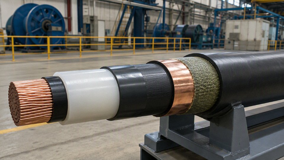
Sheath choices: PVC, PE, HDPE, and LSZH
The outer sheath is the cable’s working jacket. It does not carry the phase voltage in a normal design, but it protects the screen, armor, water barrier, and insulation system from the plant environment. In practice, sheath failures are often caused by ordinary things: crushed duct edges, poorly deburred tray supports, rodents in an old cable basement, diesel contamination near a generator day tank, or sunlight on an exposed riser.
| Sheath material | Where it fits well | Main limitations to check |
|---|---|---|
| PVC | General industrial use, cable trays, utility distribution, projects needing economical flame-retardant sheathing | Smoke, halogen acid gas, and low-temperature performance may not satisfy tunnels, public buildings, or special safety codes |
| PE | Outdoor, damp locations, ducts, direct burial where moisture resistance matters | Normally weaker fire behavior than PVC unless specially compounded |
| HDPE | Direct burial, abrasion-prone pulling routes, rough ducts, stronger mechanical jacket requirement | Stiffer handling; fire performance must be verified |
| LSZH | Tunnels, metro systems, public infrastructure, data centers, enclosed substations, offshore-like confined areas | Higher cost; mechanical and UV performance must be matched to the exact compound |
PVC is still widely used because it is cost-effective, familiar to installers, and can provide general flame retardance and mechanical protection. It is often a sensible sheath for industrial plants, outdoor trays with suitable UV grade, and utility work where halogen-free or low-smoke performance is not specified. Its weakness is not that it is “bad”; the issue is that during fire it can release dense smoke and halogen acid gases, depending on formulation. That matters in evacuation routes, tunnels, underground stations, and rooms full of sensitive switchgear.
PE and HDPE sheaths are selected when moisture resistance, abrasion resistance, burial durability, and outdoor toughness matter more than inherent flame performance. HDPE is harder and more abrasion-resistant, which helps during long duct pulls and rocky direct-burial routes, but it can be less pleasant to handle in cold weather and on tight tray bends. Standard PE-family sheaths generally need special flame-retardant compounding if the installation has strict fire propagation requirements.
LSZH sheaths are chosen to reduce smoke toxicity and corrosive gas generation in enclosed or public-facing assets. This is common in metro systems, tunnels, building risers, airports, hospitals, data centers, and similar infrastructure where smoke can do as much operational damage as flame. The buyer should check the actual smoke density and halogen acid gas evidence rather than accepting “LSZH” as a single universal performance level.
A cable described as LSZH will always be suitable for tunnels and metro systems.False
LSZH is a material family, not a complete approval. Tunnel and metro projects may require specific flame spread, smoke density, toxicity, circuit integrity, installation, and local authority compliance tests.
Special sheath requirements buyers should name clearly
Special sheath requirements should be written as performance needs, not vague adjectives. A purchase request saying “chemical-resistant sheath” is too loose; a cable exposed to transformer oil, diesel, hydraulic fluid, seawater, fertilizer dust, and caustic washdown may need different compounds.
Specify the required resistance or behavior for:
- Oil and hydrocarbon exposure: transformer oil, diesel, lubricants, hydraulic fluids, or petrochemical vapors.
- UV resistance: outdoor tray, rooftop, desert, high-altitude, or long-term open-air storage before installation.
- Low-temperature flexibility: cold-region pulling, winter commissioning, refrigerated facilities, or exposed mountain sites.
- Anti-termite and anti-rodent protection: direct burial, tropical soil, rural substations, old utility tunnels, or grain and food plants.
- Flame retardance: limited flame propagation for trays, shafts, substations, and industrial fire zones.
- Fire-resistant circuit integrity: emergency feeders, fire pumps, smoke extraction, alarms, and life-safety circuits where the cable must keep operating for a specified fire duration.
- Chemical resistance: acids, alkalis, solvents, process effluent, salt spray, ammonia, or cleaning chemicals.
- Water blocking and moisture protection: longitudinal water-blocking tapes or powders, radial barriers, metallic laminate sheaths, or other project-specific designs.
Material names alone are not enough for a serious tender. Ask for compound performance tests, referenced standards such as IEC 60502-2 or the applicable project specification, oxygen index where flame behavior is being evaluated, smoke density data, halogen acid gas results for LSZH claims, UV aging evidence, oil immersion results, and any local authority approval required for the installation. The boundary is simple: without the exposure profile and compliance target, the supplier can offer a plausible cable, but not necessarily the right one.
Testing and quality assurance
A credible medium voltage cable is not “made good” at the final test station; it is kept under control from incoming material to drum release. Final electrical tests can catch gross defects, but they cannot reverse dirty insulation, unstable extrusion, poor cooling, or weak traceability. For medium voltage cable, the factory quality system matters almost as much as the published cable design.
Raw material inspection is the first filter. In a disciplined plant, the quality team does not treat copper, XLPE compound, semiconductive compound, tapes, sheath compound, armor wire, and water-blocking yarn as generic consumables. Each one affects a different failure path.
Typical incoming checks should cover:
- Conductor metal: grade confirmation, supplier certificate review, surface condition, strand diameter, strand count, lay length, oxidation, and DC resistance trend. A small resistance drift may look harmless on one reel, but across a long feeder it becomes voltage drop, heat, and loss.
- Insulation compound: batch identity, contamination control, moisture handling, storage condition, and shelf-life discipline. MV insulation is unforgiving; a pellet-handling habit that is acceptable for low voltage cable can create partial discharge sites in medium voltage insulation.
- Semiconductive screen compounds: cleanliness, dispersion, compatibility with insulation, and stripability where specified. Poor screen smoothness raises local electrical stress at the insulation interface.
- Sheath compounds: density, mechanical properties, carbon black dispersion for UV-resistant PE where applicable, flame or low-smoke requirements when specified, and compatibility with installation environment.
- Armor materials: wire or tape dimensions, zinc coating condition if galvanized, tensile condition, and corrosion protection.
- Tapes and water-blocking components: width, thickness, overlap behavior, swelling performance where required, and storage dryness. Water-blocking material that has absorbed moisture before production is already compromised.
In-process control is where many good or bad cables are really made. The conductor line checks strand build and resistance; the insulation line controls conductor screen, insulation, and insulation screen geometry; the jacketing line verifies protective layers before the cable ever reaches final test.
Key process controls usually include:
- Conductor resistance checks against the specified conductor class and size.
- Online diameter measurement to avoid slow drift during long extrusion runs.
- Eccentricity control so the insulation wall does not become thin on one side. Eccentricity matters because electric stress is not spread evenly when the insulation is off-center.
- Extrusion cleanliness control, including compound handling, filtered material flow, clean tooling, and stable line conditions.
- Screen smoothness control at both semiconductive interfaces. Tiny protrusions can become stress concentration points.
- Controlled cooling and curing, especially for XLPE systems, to avoid internal stress, voids, or inconsistent crosslinking.
- Spark testing where applicable, commonly on nonconductive sheath layers rather than through the full MV insulation system.
- Sheath thickness and surface checks before the cable is approved for marking, coiling, and drum packing.
There is a trade-off here that buyers sometimes miss. Heavy inspection can improve defect detection, but excessive reliance on end testing can slow delivery without improving the actual process. The better investment is stable extrusion, clean compound handling, calibrated measurement, and operators who stop a line when the trend moves, not only when the cable fails.
Routine electrical tests are performed on manufactured lengths according to the applicable cable standard and project specification, such as IEC 60502-2, ICEA S-93-639, AEIC CS8, or utility-specific requirements. The exact test voltage, duration, sampling plan, and acceptance criteria must come from the governing document, not from a sales brochure.
Common routine checks include:
- Partial discharge testing on medium voltage insulated cores or completed cable, depending on the standard and construction.
- AC voltage withstand testing to confirm the insulation system can tolerate the specified test stress.
- Conductor resistance measurement to verify conductor size and build quality.
- Metallic screen continuity checks for copper tape, copper wire, or other screen systems.
- Sheath integrity checks, especially for cables intended for buried, wet, or duct installations.
Partial discharge deserves special attention. PD is not just another line on a test report; it is an early warning for voids, contamination, protrusions, poor screen interfaces, or damage that creates localized electrical stress inside the insulation system. Once discharge activity exists under operating voltage, it can erode insulation over time through electrical treeing, heat, chemical degradation, and carbonized paths.
Test sensitivity and calibration matter because a poor PD test setup can give false confidence. Noise from the factory floor, long test leads, weak shielding, incorrect calibration, or unsuitable detection equipment can hide low-level discharge. Buyers should not only ask whether PD testing is performed; they should ask whether the report identifies the standard, test voltage, sensitivity or detection threshold where required, calibration record, tested length, and acceptance result.
A finished medium voltage cable that passes routine factory tests is automatically suitable for every installation environment.False
Routine tests verify specified electrical integrity at the factory, but installation suitability also depends on route temperature, pulling tension, bending radius, water exposure, fire requirements, termination design, earthing arrangement, and the applicable project standard.
Type tests and sample tests serve a different purpose from routine tests. They prove that the cable design and material system can meet the required standard under defined stress conditions, while routine tests verify manufactured lengths. Depending on the specification, these may include:
- Bending tests to confirm mechanical behavior before electrical testing.
- Heating cycle voltage tests to evaluate insulation performance under thermal expansion and contraction.
- Impulse voltage tests where required for the voltage class and standard.
- Hot set tests for XLPE crosslinking verification.
- Insulation and sheath thickness measurements on samples.
- Aging tests for insulation and sheath materials.
- Tensile strength and elongation tests before and after aging.
- Flame tests for fire-performance cable constructions where specified.
- Water penetration tests for longitudinally water-blocked designs.
The boundary is straightforward: type test reports support a design family under defined construction and standard conditions; they do not replace routine tests on each delivered production length, and they may not cover a modified sheath, different armor, changed conductor screen compound, or special project requirement.
For procurement, the document package should be specified before the purchase order is released. At minimum, buyers should request:
- Routine test reports for delivered drums or lengths.
- Factory acceptance test records, if FAT witnessing is required.
- Certificate of conformity referencing the applicable standard and purchase specification.
- Material data or material compliance statements for insulation, sheath, armor, and water-blocking components where relevant.
- Drum schedule with cable length, drum number, gross weight, net weight, and dimensions.
- Packing list and shipping marks.
- Traceability records linking production batch, material lots, and test results.
- Installation recommendations covering pulling tension, bending radius, storage, handling, and termination precautions.
- Warranty terms with clear scope, duration, exclusions, and claim procedure.
For international projects and bulk procurement, this is where supplier structure becomes practical rather than promotional. Jinda’s integrated R&D, production, sales, technical support, and after-sales service structure, supported by large-scale manufacturing capacity, is relevant because cable quality problems often need fast cross-functional answers: production batch traceability, engineering review, documentation correction, packing clarification, and site feedback cannot sit in separate silos for weeks. A serious buyer should still verify the exact standard, test plan, inspection hold points, language of documents, and project-specific approvals before release to manufacture.
Common failure causes
Most medium voltage cable failures are not “bad cable” in isolation; they are cable-system failures involving the conductor, insulation, sheath, joints, terminations, bonding, grounding, protection settings, civil work, and installation workmanship. A well-made cable installed with the wrong surge protection, pulled around an abusive bend, or terminated by an untrained crew can fail earlier than a lower-cost cable used inside its real design limits.
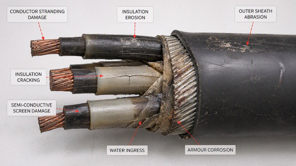
Electrical overstress
Electrical overstress starts when the cable system sees voltage stress above what the insulation, screen system, and accessories were selected to handle. The obvious case is an incorrect voltage rating, but the more common plant-floor cases are less clean:
- Wrong system voltage assumption, such as applying a cable based only on nominal phase-to-phase voltage while ignoring grounding method and possible earth-fault duration.
- Poor grounding assumptions, especially on resistance-grounded, ungrounded, or impedance-grounded systems where a healthy phase may experience elevated phase-to-ground voltage during a fault.
- Switching surges from capacitor banks, large motors, transformers, vacuum breakers, and long feeder energization.
- Lightning impulse exposure, particularly on outdoor feeders, overhead-to-underground transitions, mining sites, wind farms, and remote pump stations.
- Resonance or ferroresonance, usually tied to transformer switching, lightly loaded circuits, cable capacitance, and instrument transformers.
- Inadequate surge protection, including missing arresters, arresters installed too far from the equipment being protected, poor arrester grounding, or incorrect arrester rating.
The mechanism is straightforward: higher electric field accelerates insulation defects, raises partial discharge risk at voids or interfaces, and increases stress at terminations where the screen is cut back. XLPE insulation can tolerate normal operating stress when the cable and accessories match the system design, but it is not a cure for bad protection coordination.
Thermal failure
Thermal failure is usually slow before it becomes sudden. The insulation ages faster, shields and screens run hotter, joint resistance rises, and a cable that passed commissioning tests may start tripping during summer peaks or after production expansion.
Common thermal drivers include:
- Sustained overload beyond the ampacity basis used during design.
- Poor soil thermal resistivity, especially dry sand, ash fill, rocky backfill, or seasonal drought conditions.
- Excessive grouping or trefoil spacing errors, where one feeder heats the next.
- Blocked or water-filled ducts, depending on the assumed installation condition used in ampacity calculations.
- Undersized conductors selected from purchase price pressure rather than load growth and emergency loading needs.
- Harmonic heating, mainly from variable frequency drives, rectifiers, furnaces, UPS systems, and other nonlinear loads.
- High ambient temperature, common in cable trays near furnaces, boiler houses, rooftops, enclosed tunnels, and poorly ventilated electrical rooms.
Typical XLPE medium voltage cables are often designed around a 90°C maximum conductor temperature in normal operation, with higher emergency and short-circuit temperatures only when permitted by the applicable standard and project specification. That does not mean the whole installed system can be run casually at those limits. Terminations, joints, duct banks, soil, and adjacent circuits decide whether the paper ampacity survives contact with the site.
Moisture, water treeing, and sheath damage
Water-related failures are especially frustrating because the cable may look acceptable from the outside until testing shows insulation deterioration. Water treeing in polymeric insulation is a long-term ageing process driven by moisture, electric stress, and time; it is not the same as an immediate puncture, but it can reduce dielectric strength until a surge or switching event finishes the job.
Moisture paths usually come from:
- Damaged outer sheath during pulling, backfilling, tray work, or later excavation.
- Poor water-blocking design for wet ducts, direct burial, river crossings, or flood-prone tunnels.
- Wet terminations or joints, including condensation inside outdoor boxes and poorly sealed glands.
- Long-term submersion beyond the design basis, where a “moisture resistant” design is mistaken for a continuously submerged cable.
- Unsealed cable ends stored outdoors before installation. I still see cable drums with plastic caps missing after a rainy weekend; that is not a small housekeeping issue.
Radial and longitudinal water barriers, metallic laminates, lead sheaths, water-blocking tapes, and swelling powders can all help, but each adds cost, stiffness, manufacturing complexity, or termination difficulty. The preferred choice flips when the route changes from a dry industrial tray to a wet duct bank or coastal installation.
Mechanical damage
Mechanical damage often happens before energization. Excessive pulling tension can stretch conductors or distort insulation screens. High sidewall pressure at bends can deform the cable. Sharp bends can crack sheath materials, disturb screen geometry, or create stress points that later become partial discharge sites.
Watch for these practical causes:
- Pulling without calibrated tension control or without respecting the cable manufacturer’s pulling limits.
- Small-radius bends at manholes, switchgear entries, transformer boxes, and tray drops.
- Crushing and impact from forklifts, dropped tools, trench compaction, or careless drum handling.
- Abrasion through rough ducts, damaged tray edges, concrete openings, or unprotected risers.
- Poor trench backfill, including sharp stones, construction debris, slag, or uneven bedding.
- Inadequate route protection, such as missing warning tape, slabs, marker posts, or as-built route records.
Mechanical abuse is a good example of a failure that procurement cannot solve alone. A tougher sheath or armored cable helps, but it does not make up for an excavator bucket finding an unmarked feeder.
Accessory-related failures
Joints and terminations are the weak links in many medium voltage systems because they depend heavily on workmanship. Factory cable production is controlled; field accessory installation happens in dust, humidity, cramped switchgear compartments, wind, night shifts, and sometimes with a supervisor asking why the feeder is not back online yet.
Typical accessory failure causes include:
- Incorrect stress control, especially wrong screen cutback length or poorly installed stress cones/tubes.
- Contaminated joint interfaces, from dust, semicon particles, moisture, fingerprints, or solvent residue.
- Wrong connector crimping, including incorrect die sets, under-crimping, over-crimping, or mixing copper and aluminum hardware without proper design.
- Incompatible kits, such as using a termination kit outside its conductor size, insulation diameter, voltage class, or screen construction range.
- Insufficient installer training, particularly for cold-shrink, heat-shrink, separable connectors, and taped joints.
A medium voltage accessory should be treated as a precision electrical component assembled in the field, not as a commodity fitting. If the plant does not control cleanliness, tooling, torque, heating practice, and installer qualification, the best cable on the drum can still become the cheapest part of the failure.
Corrosion and environmental attack
Metallic screens, copper tapes, wire screens, armor, lead sheaths, aluminum moisture barriers, and grounding connections all need the right environment assumptions. Corrosion may increase screen resistance, weaken fault-current paths, compromise sheath integrity, or create intermittent bonding problems that are hard to find during routine inspection.
Risk increases with:
- Coastal salt exposure.
- Acidic or alkaline soils.
- Industrial chemical contamination.
- Stray DC currents near rail, cathodic protection, or electrochemical plants.
- Dissimilar metal contact without suitable connectors or transition hardware.
- Poorly sealed grounding links, link boxes, and sheath bonding hardware.
The trade-off is not simply “more metal is better.” Armor improves mechanical protection but adds handling weight and termination labor. Lead sheaths offer strong moisture resistance in some applications, but they bring weight, bending, environmental, and regulatory considerations that must be checked against the project specification and local rules.
Manufacturing and procurement risks
Some failures are bought before they are installed. The usual procurement traps are not dramatic; they are vague specifications, incomplete datasheets, and weak supplier verification.
Buyers should control these risks:
- Unsuitable standards, such as requesting a cable that does not match IEC 60502-2, IEC 60840 where applicable, ICEA, AEIC, IEEE, utility, or project requirements.
- Unverified suppliers with unclear production controls or no credible type test and routine test documentation.
- Counterfeit or recycled certificates that do not match the factory, cable construction, voltage class, batch, or delivery date.
- Inadequate testing requirements, especially missing partial discharge, voltage, conductor resistance, sheath integrity, or dimensional checks as required by the applicable standard.
- Mixed batches without traceability across drums, accessories, and test records.
- Unclear technical specifications, where screen area, water blocking, sheath material, flame performance, conductor class, and installation conditions are left open.
Most medium voltage cable faults are caused by the installed cable system, not only by the factory-made cable length.True
This is consistent with common utility and industrial maintenance experience, but the exact split varies by network design, installation quality, accessory practice, environment, and how failures are classified. It should not be used as a universal statistical percentage without project-specific failure records.
Symptoms and diagnostic indicators
| Symptom or finding | Likely areas to investigate |
|---|---|
| Partial discharge activity | Voids, protrusions, screen cutback errors, contaminated joints, ageing insulation, poor stress control |
| Declining insulation resistance | Moisture ingress, sheath damage, contamination, severe insulation ageing |
| Sheath test failure | Outer jacket damage, poor bonding hardware, corrosion, installation abrasion |
| Local hot spot on thermal imaging | Loose termination, high-resistance crimp, overloaded phase, poor ventilation, unbalanced load |
| Repeated protection trips | Cable fault, accessory defect, incorrect relay settings, transient overvoltage, downstream equipment fault |
| Visible swelling, cracks, or sheath deformation | Overheating, chemical attack, mechanical crushing, incompatible environment |
| Corrosion at screens, armor, or grounding points | Water ingress, soil chemistry, poor sealing, galvanic action, stray current |
| Burn marks or tracking at terminations | Contamination, moisture, inadequate creepage distance, poor stress grading, overvoltage exposure |
Diagnostics should not stop at locating the fault distance. The investigation needs to ask why that point failed: Was the sheath damaged during installation? Was the joint kit correct for the cable diameter? Did relay settings allow long earth-fault duration? Did the duct bank run hotter than the design assumed? That is where prevention usually sits.
Procurement specification checklist
Use the purchase specification as a controlled engineering document, not as a short RFQ note. A usable medium voltage cable enquiry should lock down the following items before suppliers price it:
- Cable identity and governing standard
- Full rated voltage, written in the correct form, such as 8.7/15 kV, 12/20 kV, or 26/35 kV under IEC practice, or the applicable North American voltage class where relevant.
- Standard and edition, such as IEC 60502-2, IEC 60840 where applicable, ICEA S-93-639, AEIC CS8, IEEE 404, IEEE 48, plus any utility or project specification.
- System earthing method, because screen and insulation stress assumptions can change between solidly earthed, resistance-earthed, and isolated systems.
- Single-core or three-core construction, and the number of conductors required.
- Conductor, insulation, screen, sheath, and armor
- Conductor material: copper or aluminum.
- Conductor size and class: compacted stranded, stranded circular, sector-shaped where applicable.
- Insulation material, usually XLPE for many modern MV power projects, unless the project specifies another system.
- Conductor screen and insulation screen type, including whether the insulation screen is strippable or bonded.
- Metallic screen design: copper tape, copper wire screen, concentric neutral, lead sheath, or other specified arrangement.
- Outer sheath compound: PVC, PE, LSZH, anti-termite, anti-rodent, oil-resistant, UV-resistant, or flame-retardant grade as required.
- Armor type: steel wire armor, steel tape armor, aluminum wire armor for single-core AC cable where magnetic losses matter, or unarmored design for duct systems.
- Flame rating, smoke and halogen requirements, and any tunnel, building, mine, offshore, or utility fire-performance clauses.
- Electrical performance data
- Ampacity, including the calculation basis: buried, duct, tray, air, soil thermal resistivity, ambient temperature, grouping, depth of laying, and load factor.
- DC conductor resistance at reference temperature.
- AC resistance and losses where relevant, especially on larger single-core systems.
- Short-circuit rating of the conductor.
- Metallic screen or sheath earth-fault rating and permitted fault duration.
- Nominal insulation thickness and minimum thickness requirement.
- Inner and outer sheath thickness.
- Permissible conductor temperatures, commonly up to 90°C for XLPE in normal service, with emergency overload and short-circuit limits only where allowed by the applicable standard and cable design.
Two quotations with the same voltage and conductor size can still describe materially different cables if the screen cross section, sheath compound, armor design, and test scope are not fixed. That is where many “cheaper” MV cable offers become expensive during installation or fault review.
- Installation and handling data
- Minimum bending radius for installed condition and during pulling.
- Maximum pulling tension, including whether the limit is based on conductor pulling eye, cable stocking grip, or combined pulling method.
- Approximate overall diameter and manufacturing tolerance.
- Cable weight per meter.
- Standard and maximum drum length.
- Drum flange diameter, barrel diameter, overall drum width, and gross drum weight.
- Recommended pulling method: winch, rollers, duct pulling, lubricant type, sidewall pressure control, or special handling for long vertical risers.
This information affects site labor more than buyers sometimes expect. A cable that is 8 mm larger in diameter may no longer fit an existing duct with acceptable pulling friction. A heavier armored cable may need a different drum stand, forklift capacity, or crane booking. On a tight shutdown, those details are not paperwork; they are the difference between energizing on Sunday night and explaining a delay on Monday morning.
- Quality, compliance, and traceability
- Type test evidence for the relevant cable design or cable family.
- Routine factory test records for the supplied batch.
- Sample test reports where required by the standard or contract.
- Material certificates for conductor, insulation compound, screen materials, sheath compound, and armor where specified.
- Factory inspection and test plan.
- Third-party inspection hold points, if the buyer or utility requires them.
- Cable marking details: manufacturer, voltage, size, standard, year, meter marking, drum number.
- Packing list, drum schedule, and preservation method.
A medium voltage cable procurement specification should define both the cable design and the evidence required to prove that the delivered drums match that design.True
Design requirements alone do not verify supply quality. Routine test records, traceability, marking, and packing information connect the manufactured cable to the approved specification and delivered drums.
- Project logistics and batch control
- Required delivery schedule, with partial shipment rules if the project is staged.
- Drum numbering and cable length allocation by feeder or route.
- Export packing requirements and seaworthy drum protection.
- Destination port, inland site, or warehouse delivery terms.
- Storage conditions, including UV exposure, drum standing direction, end cap sealing, humidity, and long-term outdoor storage limits.
- Spare length percentage or fixed spare length per route.
- Batch consistency requirement, especially for multi-drum feeder circuits where diameter, marking, and accessory compatibility should remain uniform.
- Commercial and technical support terms
- Warranty period and what it covers.
- Drawing review process before production release.
- Response time for technical clarification.
- Installation guidance documents or accessory coordination support.
- Support for buyer inspection or third-party inspection.
- Long-term supply capability for repeat projects, framework agreements, or future maintenance stock.
To compare quotations fairly, normalize the items that change cost before comparing the final price. Bring every offer back to the same standard, conductor material, conductor size, insulation grade, metallic screen area, sheath compound, armor type, flame requirement, testing scope, delivery term, packing level, and documentation package. The trade-off is straightforward: a tightly specified RFQ takes more engineering time up front, but it reduces commercial noise and prevents suppliers from winning on omissions. The exception is an early budget estimate, where a controlled assumption sheet may be enough, provided nobody treats it as a construction-ready cable order.
Jinda is positioned for international medium voltage cable projects where buyers need manufacturing capacity, engineering communication, bulk production coordination, export handling, and stable long-term supply partnerships. With multiple production bases, large manufacturing space, and experience supplying customers in more than 50 countries, the practical fit is strongest where the purchase is not just a few drums, but a repeatable supply program that needs consistent documentation and disciplined project coordination.
Frequently asked questions
What voltage range is considered medium voltage?
In IEC-style projects, medium voltage power cables commonly run from 3.6/6 kV up to 26/35 kV. In North American utility and industrial work, the common classes are often 5 kV through 46 kV. The exact boundary depends on the standard, utility practice, and project specification, so do not buy by the phrase “medium voltage” alone.
Is 1 kV cable medium voltage or low voltage?
A 1 kV AC cable is normally treated as low voltage, not medium voltage. Medium voltage cable uses a very different insulation screen, metallic screen, termination system, and test regime; a 0.6/1 kV power cable is not a substitute for a 3.6/6 kV or 8.7/15 kV circuit.
What is the difference between medium voltage and high voltage cable?
Medium voltage cable is typically used for distribution inside plants, utilities, renewable sites, substations, mines, and large infrastructure. High voltage cable is designed for higher electric stress, longer transmission distances, and stricter accessory, testing, and installation controls. The construction concept is similar, but the consequences of small defects become much less forgiving as voltage rises.
What is the difference between XLPE and EPR insulation?
XLPE is a cross-linked polyethylene insulation with low dielectric loss, good thermal rating, and wide use in industrial and utility MV cables. EPR is a rubber-based insulation, usually more flexible and often favored where handling, vibration, moisture exposure, or frequent movement matter. XLPE is usually the economical default; EPR can justify its cost where flexibility and wet-service behavior are more valuable than minimum diameter or lowest losses.
Why does a medium voltage cable need a metallic screen?
The metallic screen controls the electric field, provides a path for capacitive charging current, and can carry earth-fault current long enough for protection to operate. Without a correctly bonded screen, voltage stress becomes uncontrolled around the insulation system. That is exactly where partial discharge, tracking, and accessory failures start.
Can medium voltage cables be installed directly underground?
Yes, if the cable is designed and specified for direct burial. The buyer must check sheath material, water blocking, armor or mechanical protection, termite or rodent exposure, soil thermal resistivity, burial depth, pulling tension, and local installation rules. A cable that survives in a concrete trench may not survive in rocky backfill with poor compaction and standing water.
How long does a medium voltage cable last?
A well-selected and properly installed MV cable often serves for 25 to 40 years or more. Life is shortened by overheating, water ingress, poor terminations, excessive bending, sheath damage, aggressive soil, and repeated overloads. Cable life is not only a factory quality question; the installation crew and maintenance regime have a large vote.
What tests should be performed before energizing a new cable circuit?
Typical pre-energization checks include:
- Visual inspection of cable route, glands, terminations, and joint positions
- Conductor continuity and phase identification
- Screen continuity and bonding verification
- Sheath integrity test where applicable
- Insulation resistance measurement
- VLF withstand, tan delta, or partial discharge testing when specified
- Torque check on lugs and earth connections
- Protection, earthing, and switching coordination review
The exact test voltage and method should follow the project standard, utility requirement, and accessory manufacturer instructions.
Can copper and aluminum medium voltage cables be used interchangeably?
Not directly. Aluminum can often replace copper if the conductor size is recalculated for ampacity, voltage drop, short-circuit rating, pulling limits, and termination compatibility. Aluminum is lighter and usually cheaper per installed ampere, but it needs larger cross-section and correct bi-metallic or aluminum-rated connectors. Mixing materials casually is how hot lugs and nuisance outages appear months later.
How should I choose between armored and unarmored cable?
Choose armored cable where mechanical damage risk is credible: direct burial, industrial yards, mining areas, exposed tray runs, traffic crossings, or rough maintenance zones. Unarmored cable can be suitable inside controlled ducts, clean cable trenches, switchgear rooms, or protected tray systems. Armor adds cost, weight, diameter, and termination work, so it should solve a real installation risk rather than just “look safer.”
Why do terminations and joints fail so often?
Terminations and joints fail because they concentrate electric stress and depend heavily on workmanship. Common causes include poor cable stripping, cuts in the insulation screen, contamination, moisture, wrong stress-control parts, bad crimping, insufficient heating of shrink components, and incorrect screen bonding. A good cable can still fail early if the accessory kit is installed like low-voltage hardware.
What information should I send to a cable manufacturer for a quotation?
Send enough detail for the manufacturer to quote the same cable you actually need:
- Rated voltage, system voltage, frequency, and earthing method
- Standard required, such as IEC 60502-2, ICEA, AEIC, IEEE, or project specification
- Conductor material and size, or load data for sizing support
- Number of cores and circuit arrangement
- Insulation type, sheath type, armor requirement, and water-blocking requirement
- Installation method: duct, tray, direct burial, tunnel, air, or submarine/other special route
- Ambient temperature, soil data if buried, grouping, and route length
- Short-circuit current and duration
- Fire, smoke, UV, oil, chemical, rodent, or termite requirements
- Drum length, packing, delivery schedule, and required test documents
Your cable specification review
A medium voltage power cable should be purchased as a complete engineered cable system, not as “15 kV, 240 mm²” written on a requisition line. The cable, accessories, grounding arrangement, installation method, and test plan have to match the same electrical and site conditions, or the weak point will usually show up at a termination, joint, shield connection, or overheated section of route.
Before issuing the purchase order, verify these items against the project design and the applicable standard, not just against a previous job:
- Voltage rating and system grounding: Confirm phase-to-phase voltage, phase-to-earth stress, neutral grounding method, and whether the cable rating is suitable for earth-fault duration.
- Fault level and short-circuit duration: Check conductor and metallic screen capacity under the specified fault current. A screen sized only for steady-state charging current can become the failure path during a fault.
- Load current and thermal conditions: Include grouping, burial depth, duct fill, ambient temperature, soil thermal resistivity, tray ventilation, and seasonal extremes. In practice, this is where many “correct” conductor sizes become marginal.
- Shielding, armor, and sheath: Match metallic screen, armor, and outer sheath to mechanical risk, moisture exposure, corrosion, rodents, hydrocarbons, sunlight, and pulling conditions.
- Fire and installation requirements: Confirm flame, smoke, halogen, or fire-resistance requirements where cables pass through tunnels, substations, industrial buildings, offshore modules, or public infrastructure.
- Applicable standards and project specifications: State IEC, ICEA, AEIC, IEEE, utility, or owner specifications clearly, including any inspection, marking, packing, or documentation clauses.
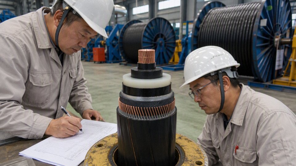
Review the accessories at the same time as the cable. Terminations, joints, separable connectors, bonding leads, link boxes, sheath voltage limiters, earthing points, pulling grips, and installation tooling all affect service reliability. One missing bonding detail can create circulating current, sheath heating, nuisance alarms, or a termination that fails long before the cable insulation itself is aged.
For a reliable quotation, send the supplier the route drawings, single-line diagram, load data, fault level, grounding method, installation conditions, required standards, cable quantities, drum length preferences, delivery schedule, inspection requirements, and any photos of trenches, trays, ducts, or switchgear interfaces. If the project is still early-stage, say so; a budget quotation and a construction-ready quotation need different assumptions.
Jinda can support this review from the manufacturing side. Established in 1987, Shandong Jinda Special Cable Group Co., Ltd. operates five production bases across China, with 470,000 square meters of manufacturing space, more than 1,000 employees, and cable customers in more than 50 countries. For your next medium voltage cable purchase, request a specification review, technical recommendation, or project quotation from Jinda with the project data above so the proposal can be checked against the actual operating conditions, not only the nominal voltage class.