Choosing the wrong underground wire usually does not fail on day one; it fails after water, soil pressure, heat, or a poor termination has had time to work on it. That turns a simple cable run into nuisance tripping, insulation breakdown, excavation, production delays, or a service call nobody budgeted for. The right direction is to match the cable type, burial method, insulation rating, cover depth, and voltage-drop limit before the trench is closed.
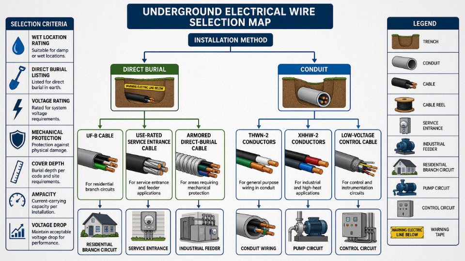
For underground electrical wiring, use cable or conductors specifically rated for wet locations and direct burial or underground conduit service, such as UF cable for many residential branch circuits, USE-rated service entrance cable where permitted, or individual wet-rated conductors like THWN-2 pulled through approved conduit. Final selection depends on code, load, soil, depth, and installation method.
The confusing part is that “underground wire” is not one product. A landscape lighting circuit, a farm feeder, a pump supply, and a factory yard distribution run may all sit in soil, but they do not ask the cable to survive the same heat, moisture, mechanical abuse, or inspection requirements.
Direct burial versus conduit
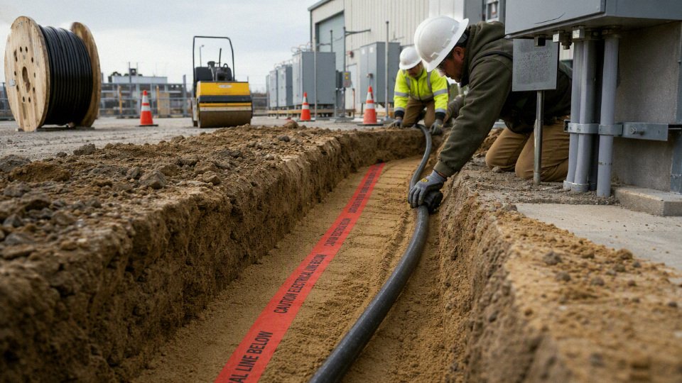
Direct burial is usually the lower-cost choice for long, open routes where the cable is listed for soil contact and future modification is unlikely. Conduit earns its keep where mechanical protection, clean equipment entry, organized routing, or later replacement matters. The deciding issue is not “which is better,” but which installation leaves less risk over the life of that particular run.
What direct burial really means
Direct burial does not mean taking ordinary building wire and putting it in a trench. It means using a cable manufactured and listed for direct contact with soil and moisture, with insulation, jacket, fillers, armoring where applicable, and markings suitable for that service. Depending on the country and project specification, that may include underground feeder cable, armored power cable, direct-burial rated low-voltage control cable, or other approved constructions.
The practical advantage is simplicity. On a long straight route across a yard, solar field, farm facility, pump station, or between plant buildings, direct-burial cable avoids hundreds of meters of PVC or HDPE raceway, couplings, elbows, spacers, glue joints, and pull points. It also removes a common installation problem: excessive pulling tension. A heavy multi-core cable can be laid into the trench from a reel with rollers and a trained crew; it does not always need to be dragged through bends, sweeps, and half a dozen underground boxes.
That simplicity has a condition attached. The route must be suitable for burial without unacceptable risk from digging, vehicle loads, rocks, rodents, chemical exposure, settlement, or future civil work. Sand bedding, warning tape, route markers, and as-built drawings are not paperwork decoration here; they are what keep the next excavator bucket from becoming the fault locator.
What an underground conduit system really means
An underground conduit system uses an approved raceway — commonly PVC, HDPE, rigid metal conduit, intermediate metal conduit, or another permitted duct system — with individual wet-location conductors or suitable cables installed inside it. The raceway is part of the electrical installation, not just a sleeve tossed into the trench. Its material, burial depth, bend radius, support at transitions, expansion allowance, and fittings all affect service life.
Conduit has a strong case in dense industrial sites. Around switchgear rooms, MCCs, outdoor panels, loading areas, pipe racks, wastewater plants, and machinery foundations, the ground is rarely “open” for long. Someone will add a slab, cut a trench for compressed air, install a drain, or move a fence line. A defined raceway bank gives maintenance and project teams a cleaner map of where circuits are, and it provides better mechanical protection than a bare buried cable in many exposed areas.
It also makes transitions into equipment neater. A conduit riser into a disconnect, junction box, motor terminal area, or control cabinet is easier to support, seal, label, and inspect than a cable emerging from soil with improvised protection. In plants where electricians are troubleshooting at 2 a.m. with rainwater running across the yard, that organization matters.
The wet-location trap
A common mistake is assuming that conduit makes the underground wiring “dry.” It does not. Underground raceways are normally treated as wet locations because water enters through condensation, imperfect joints, grade changes, damaged fittings, and temperature cycling. Even a beautifully glued PVC run can collect water over time.
Underground conduit should be treated as a dry location because it protects conductors from soil.False
Underground raceways are generally expected to contain moisture or standing water over their service life, so conductors and cables installed in them must be suitable for wet locations unless the applicable code and product listing clearly say otherwise.
The mechanism is simple: soil temperature changes slowly, air inside the conduit changes faster, and moisture condenses on the inner wall. Water also finds low points. If the conductor insulation is only rated for dry building interiors, the failure may not show up during commissioning; it may appear months later as nuisance ground faults, insulation resistance decline, or tracking at terminations.
Cost, pulling, and serviceability trade-offs
Direct burial often wins installed cost on open routes because the crew installs fewer components and spends less time assembling raceway. The trade-off is exposure. If the cable is damaged later, repair usually means excavation, splicing with a listed underground method, and accepting a buried joint that should be mapped and protected. In a production plant, the excavation permit and downtime can cost more than the original cable.
Conduit often wins on protection and future service, but only if it was designed as a pullable system. I have seen underground ducts that looked good on drawings and were almost useless later because nobody respected the bending, fill, and pulling rules. A conduit system is replaceable only when the design accounts for:
- Pull box spacing and access after landscaping, paving, or equipment installation
- Total bend angle between pull points, including the bends nobody counts at risers
- Minimum bend radius for the conductor or cable, not just the conduit
- Conduit fill ratio and heat effects from grouped circuits
- Pulling tension and sidewall pressure limits
- Compatible pulling lubricant
- Drainage, sealing, and corrosion risk at metallic components
- Spare ducts or spare capacity where later expansion is likely
Poor conduit can be worse than direct burial. A collapsed HDPE duct, a PVC run with too many tight sweeps, or a duct bank full of silt gives the owner the cost of conduit without the maintenance benefit. The preferred choice flips toward direct burial when the route is long, accessible, stable, lightly congested, and unlikely to change. It flips toward conduit where excavation risk, mechanical damage, future replacement, or circuit organization carries more value than the first-cost saving.
Hybrid designs are normal
Many good installations use both methods. A direct-burial cable may run freely across an open section, then pass through conduit sleeves where protection is needed. Typical sleeve locations include:
- Under roads, driveways, rail crossings, and forklift routes
- At risers from below grade to panels, poles, junction boxes, or equipment
- Near foundations, retaining walls, and building entries
- Through walls, ducts, and sleeves under slabs
- Where rock, debris, or sharp backfill cannot be reliably controlled
- At areas likely to be excavated again for utilities, drains, or process piping
The sleeve needs to be large enough and smooth enough for installation without damaging the jacket. At vertical risers, physical protection and UV exposure matter as much as burial suitability; a cable jacket that is fine in soil is not automatically acceptable exposed in sunlight unless its marking and manufacturer data support it.
Code and specification checks before choosing
The final selection has to match the local electrical code, authority requirements, utility rules, project specification, and manufacturer installation instructions. Minimum cover depth, permitted wiring methods, warning tape requirements, separation from other services, grounding and bonding, cable ampacity, conduit fill, burial in concrete, and wet-location conductor ratings are not universal. Typical cover depths can range from shallow protected low-voltage landscape circuits to 600 mm or more for many branch-circuit installations, but the controlling rule is the one enforced on that site.
For procurement, do not buy on the words “underground cable” alone. Ask for the actual standard, listing or certification, voltage rating, insulation temperature rating, wet-location suitability, direct-burial approval where needed, armoring or jacket construction, and installation limitations. For engineering, mark the route class on the drawing: direct burial, conduit, sleeve-only protection, duct bank, road crossing, riser, and building entry. That small discipline prevents the classic field argument where the civil crew, electrician, and buyer each assumed a different installation method.
Underground cable types
The right underground “wire” family depends first on where it sits in the system: branch circuit, service entrance, site distribution, control, pump, or specialty infrastructure. Do not buy by conductor size alone; buy by the cable marking, insulation system, wet-location rating, mechanical protection, and the code rule that permits that product in that location. The same copper size can be perfectly acceptable in one trench and illegal or short-lived in another.
Residential direct-burial branch circuit cable
UF-B is the common residential direct-burial cable where local electrical code recognizes it. It is typically used for:
- Outdoor lighting circuits
- Detached garages or small outbuildings
- Yard receptacles
- Gate operators
- Small pumps
- Modest residential feeders, where permitted and properly sized
UF-B is built with moisture-resistant insulation and an overall construction intended for burial, but it is not a magic trench cable. It still needs proper burial depth, protection where it emerges from the ground, and routing away from damage. In practice, the weak points are not usually the middle of the run; they are the risers at walls, post lights, pump pads, and places where someone later drives a stake or trenching tooth through it.
The trade-off is cost and simplicity versus serviceability. UF-B avoids conduit for much of the route, which can save labor on a short residential run. The penalty is that replacement usually means digging it back up, and pulling in a larger circuit later is not practical. Its use also becomes less attractive as ampacity rises, run length increases, or the installation crosses driveways, rocky soil, or areas likely to be disturbed.
Wet-location building conductors in conduit
For underground raceways, the conductor must be suitable for wet locations because underground conduit is treated as wet in many codes and, in plant maintenance reality, it usually becomes wet. Common markings include:
| Conductor marking | Typical use underground | Practical selection notes |
|---|---|---|
| THWN-2 | Branch circuits and feeders in conduit | Nylon-jacketed thermoplastic insulation; verify wet-location and temperature marking |
| XHHW-2 | Feeders, services, industrial conduit runs | XLPE insulation; generally tougher insulation than many thermoplastic building wires |
| RHH / RHW-2 | Power conductors in wet or dry locations, depending on marking | Rubber or XLPE-type insulation; check exact marking and voltage rating |
| Dual-rated types | Mixed indoor/outdoor conduit paths | The printed legend controls where it can legally be installed |
Copper is common for smaller circuits and terminations that see frequent maintenance. Aluminum is often commercially sensible for larger feeders, provided lugs are rated for aluminum, terminations are prepared correctly, and torque practices are controlled. I have seen more trouble from poor aluminum terminations than from the aluminum conductor itself: wrong lug, no brushing, no oxide inhibitor where required by the connector maker, or a mechanic “tightening by feel” with a tired wrench.
Conduit compatibility matters too. PVC, HDPE, rigid metal conduit, and intermediate metal conduit behave differently under soil movement, impact, heat, and pulling tension. A long run with too many bends can turn a cheap conduit design into a cable-pulling fight, especially with larger XHHW-2 aluminum feeders.
Underground service entrance conductors
USE-2 and related underground service entrance cables are used between utility or service equipment points where the code permits them. They are built for wet underground service, often with sunlight-resistant markings when the installation requires exposed transitions.
The important procurement trap is interior use. Some USE conductors are not permitted inside buildings unless they also carry a suitable building-wire marking, such as RHW-2, XHHW-2, or another rating accepted by the applicable code. A buyer ordering “USE cable” for a service lateral that enters a building should have the engineer or authority having jurisdiction confirm the allowed transition method before the purchase order is placed.
Low-voltage power cable for commercial and industrial sites
Commercial and industrial underground power cable commonly falls into 600 V, 0.6/1 kV, or 1 kV classes, depending on the market and project standard. These cables may use copper or aluminum conductors, PVC or XLPE insulation, and jackets formulated for moisture, abrasion, sunlight exposure before burial, and chemical contact.
Common applications include:
- Plant feeders between substations, MCC rooms, pumps, and process buildings
- Yard power for warehouses, ports, and logistics facilities
- Low-voltage distribution for water treatment, mining support areas, and renewable-energy balance-of-plant systems
- Buried circuits in cable trench, duct bank, tray-to-underground transitions, or direct burial where approved
XLPE insulation is often preferred where thermal margin, insulation resistance, and aging performance matter. PVC can be economical and flexible for lower-duty installations, but heat, oil, and long-term soil exposure requirements must be checked against the actual compound and standard. The mechanism is straightforward: higher operating temperature, poor heat dissipation in soil, and grouped circuits raise conductor temperature; that accelerates insulation aging and can force ampacity derating before the copper or aluminum size looks “full” on paper.
Medium-voltage underground distribution cable
Medium-voltage underground cable is a different product class, not just “larger low-voltage cable.” It normally includes:
- Conductor screen
- XLPE, EPR, or similar insulation system
- Insulation screen
- Metallic shield or concentric neutral
- Optional water-blocking tapes, powders, or longitudinal barriers
- Outer jacket selected for direct burial, ducts, mining, utility, or industrial exposure
These cables serve utility feeders, wind and solar collection systems, mines, large industrial distribution networks, and campus-style power systems. Shielding controls the electric field around the conductor; without the correct screen and shield system, electrical stress concentrates at defects and terminations. Water blocking reduces the movement of moisture along the cable after jacket damage, which can matter in wet duct banks and flooded trenches.
The trade-off is cost and installation discipline. A shielded MV cable with water blocking and a robust jacket costs more and demands trained termination work, but it reduces failure risk in networks where an outage can stop a line, a pump station, or a solar block. This preference stops being automatic where the system voltage, fault duty, grounding method, and protection scheme do not require MV construction; using MV cable as a vague “heavy-duty” substitute is poor specification practice.
Armored and mechanically protected cables
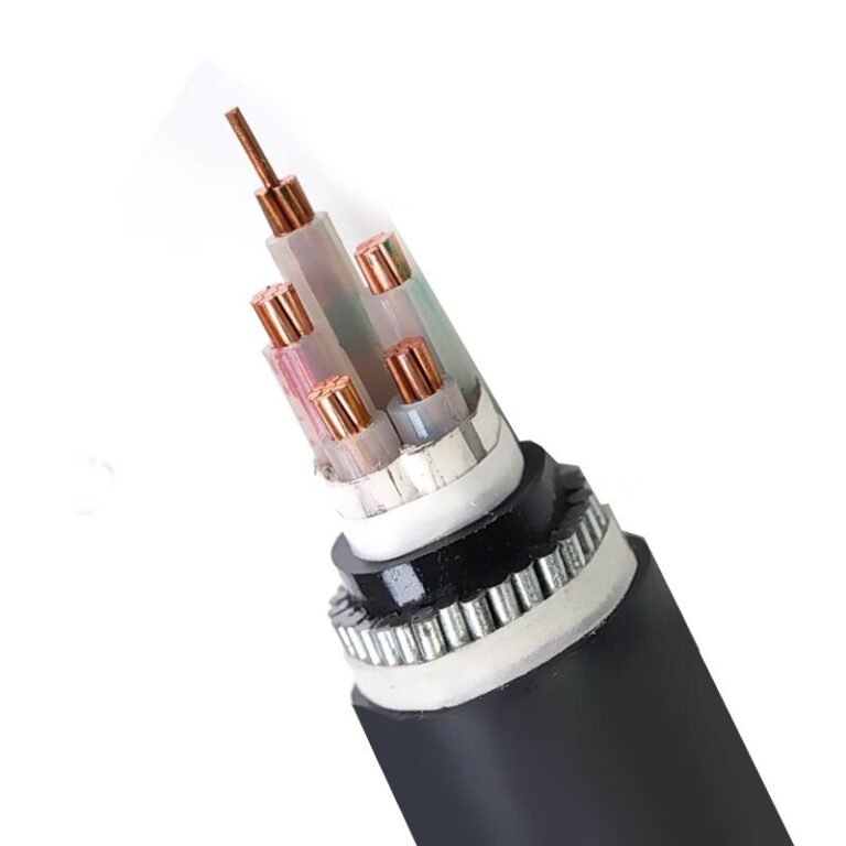
Armor is selected for mechanical risk, not appearance. Common forms include:
- Steel tape armor for general crush and impact resistance
- Steel wire armor for tensile strength and direct-burial industrial service
- Aluminum armor where weight and corrosion behavior favor it
- Interlocked armor for certain commercial and industrial routing methods
- Project-specific protection such as concrete encasement, warning tape, tiles, sand bedding, or duct banks
Rocky backfill, scrap yards, refineries, rail corridors, rodents, and areas with future excavation risk all change the cable choice. Armor adds protection, but it also adds diameter, weight, pulling difficulty, bending-radius limits, and termination complexity. If the maintenance crew cannot gland and bond the armor correctly, the design advantage gets lost at the first junction box.
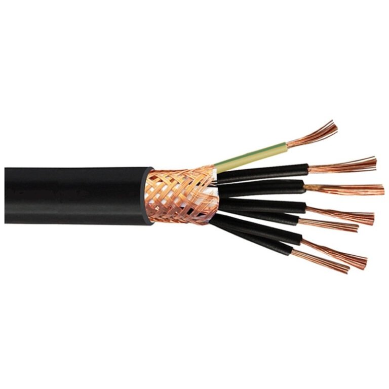
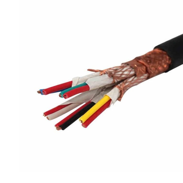
Control, instrumentation, and communication cables
Control and signal cables should not be treated as smaller power cables. They may be built as pairs, triads, multi-core control cables, shielded instrumentation cables, fiber optic cables, or data cables with moisture-blocked jackets. Selection depends on:
- Signal level and noise sensitivity
- Overall shield versus individual pair or triad shielding
- Drain wire and grounding method
- Low-smoke or flame-performance requirements in tunnels or buildings
- Separation from power circuits
- Outdoor, wet-location, and direct-burial rating
Running a 4-20 mA instrument pair in the same trench zone as a variable-frequency drive output cable without proper separation or shielding is asking for nuisance faults. The cable may be electrically continuous and still give the controls technician a week of headaches.
Submersible and pump cable
Wells, borehole pumps, irrigation pumps, aerators, and wastewater equipment often need cable rated for continuous wet or submerged service. Direct-burial rating alone may not cover immersion, oil, sewage, chlorine compounds, pump vibration, or repeated handling during pump removal.
Look for the specific pump or submersible cable construction required by the equipment manufacturer and local code. In wastewater plants, I would rather see this checked twice than have a premature failure under a wet well cover on a Friday night.
Airport, railway, solar, and other specialty underground cables
Specialty underground systems bring their own cable rules. Airport lighting cable, railway signaling and traction-related cable, photovoltaic collection cable, mining cable, cathodic protection cable, and oil-resistant industrial cable may require special voltage ratings, flame behavior, UV resistance before burial, low-temperature flexibility, oil or fuel resistance, or grounding compatibility.
Solar projects are a good example: portions of a circuit may be exposed to ultraviolet light, high ambient temperature, and DC operation before entering underground raceway or direct burial. Railway and airport circuits may have strict signaling, insulation, and fault-performance requirements. For these categories, the project specification and current standard matter more than a generic underground label.
Materials and protective layers
Underground cable life is decided less by one headline rating and more by the stack of materials around the conductor: metal, strand form, insulation, shield, jacket, armor, and water-blocking. A cable that works well in dry sand under a car park may be a poor choice in wet clay, a chemical yard, or a duct bank with high thermal loading.
Conductor metal: copper versus aluminum
Copper carries more current in a smaller cross-section, terminates more forgivingly, and usually bends better in tight equipment spaces. Aluminum costs less per ampere in many feeder sizes and weighs much less, which matters on long pulls, tray handling, and reels that already need a forklift instead of two electricians and a pipe.
The trade-off shows up at the termination, not just in the purchase order. Aluminum conductors need compatible aluminum-rated or dual-rated lugs, proper oxide removal where required, antioxidant compound where the connector manufacturer specifies it, and torque-controlled tightening. I still see people “give it a little extra” with a long wrench; that is how lugs get distorted and conductors cold-flow later. Copper is not immune to bad workmanship, but aluminum is less tolerant of casual termination practice.
The theft risk cuts the other way. Copper has a higher scrap value, so exposed cable ends, construction reels, and partially installed routes can become a security issue on open sites. Aluminum can reduce that exposure, although no cable is theft-proof if it is visible and accessible.
Conductor form and pulling behavior
Small underground branch circuits may use solid conductors where the product listing and code allow it, but large underground feeders are usually stranded. Stranding improves flexibility, reduces bending stress at duct entries and equipment glands, and makes pulling through sweeps less brutal on both the cable and the crew.
Common conductor forms include:
- Solid conductors: simple and compact, but stiff in larger sizes; more suited to small circuits than heavy feeders.
- Class B or similar stranded conductors: standard building and power cable construction; workable for most feeders.
- Flexible stranded conductors: useful where vibration, frequent movement, or tight terminations are expected, but termination hardware must match the strand class.
- Compacted stranded conductors: reduce outside diameter, helping with conduit fill and cable weight, though they may be less flexible than non-compacted equivalents.
- Sector conductors: shaped conductors used in some multi-core power cables to reduce overall cable diameter; good for space efficiency, but splicing and termination require the right kits and trained hands.
Pulling damage is often caused before the cable ever sees load. Sidewall pressure through bends, excessive pulling tension, and poor lubricant choice can deform insulation or score jackets. A cable with a slightly smaller diameter can save duct space, but if it is too stiff for the installed route, the saving disappears into labor, damaged reels, and rejected insulation tests.
Insulation systems
Insulation is the electrical and thermal working layer. For underground service, the material must handle voltage stress, soil moisture, operating temperature, and aging under load.
| Insulation system | Where it is commonly used | Strengths | Watch points |
|---|---|---|---|
| PVC | Low-voltage building wire and some power cable | Economical, familiar, decent flame performance in many formulations | Lower heat and moisture performance than premium thermoset systems; can stiffen in cold weather |
| XLPE | Low- and medium-voltage power cable | Good dielectric strength, common 90°C class, strong aging performance | Less flexible than EPR in many constructions |
| TR-XLPE | Medium-voltage underground distribution | Improved resistance to water-treeing compared with standard XLPE | Cost and availability vary; must be paired with correct shields and jackets |
| EPR | Medium-voltage and demanding industrial circuits | Flexible, moisture-tolerant, good electrical aging behavior | Larger diameter and higher cost in some designs |
| Rubber compounds | Portable, mining, temporary, and flexible power applications | Excellent flexibility and toughness depending on compound | Not automatically suitable for permanent burial unless listed and jacketed for it |
| Thermoplastic options | Low-voltage wet-location conductors and control wiring | Processable, economical, widely available | Thermal deformation and chemical resistance depend heavily on formulation |
| Thermoset options | Power feeders and higher-duty installations | Better thermal stability after curing | Harder to recycle; usually higher manufacturing cost |
A 90°C insulation rating does not mean the cable can always be loaded to a 90°C ampacity underground.True
Ampacity depends on soil temperature, thermal resistivity, grouping, conduit fill, burial arrangement, and termination temperature ratings. The usable ampacity must be checked against the applicable code, project method, and cable data.
Moisture is the slow enemy in many buried systems. In medium-voltage cables, water-treeing can grow through insulation under electrical stress when moisture is present over time. That is why TR-XLPE, EPR, clean semiconductive screens, and water-blocked constructions are not marketing trim on distribution circuits; they address a known aging mechanism.
Jacket compounds
The jacket is the cable’s work clothes. It takes abrasion during pulling, blocks routine moisture exposure, resists sunlight while reels sit outdoors, and decides whether the cable survives contact with oils, fuels, fertilizers, solvents, or mildly aggressive soil.
Typical jacket choices include:
- PVC: economical, flame-retardant in many grades, easy to print and process; can be less abrasion-resistant and less cold-flexible than tougher compounds.
- PE: strong moisture resistance and good electrical properties; generally weaker flame behavior unless specially formulated.
- HDPE: hard, abrasion-resistant, excellent for many direct-burial and duct applications; can be stiff, especially in cold weather.
- LLDPE: better flexibility than HDPE with good moisture resistance; often used where installation handling matters.
- LSZH: selected for tunnels, transit, buildings, and confined routes where low smoke and halogen-free fire behavior are specified; not automatically the toughest burial jacket.
- Chlorinated polyethylene: good weathering, oil resistance, and toughness in suitable formulations.
- Oil-resistant or chemical-resistant jackets: needed around refineries, fuel systems, food plants with washdown chemicals, and contaminated industrial soil; compatibility should be confirmed against the actual chemical exposure.
Sunlight exposure before burial is easy to overlook. Cable can sit on a laydown yard for months while civil work slips. If the jacket is not sunlight-resistant, UV damage may start before installation, especially on dark reels sitting through summer.
Metallic shields, screens, and grounding
Medium-voltage cables need metallic screens or shields to control the electric field around the insulation. Without that controlled field, voltage stress concentrates at air gaps, jacket defects, and termination edges. The shield also provides a path for charging current and, depending on design, a return path for fault current.
Shield design has to match the grounding plan. Copper tape, copper wire screens, concentric neutrals, and metallic sheaths all behave differently under fault current and circulating current. Bonding both ends may improve fault clearing but can create shield losses on long AC runs. Single-point bonding can reduce losses, but touch voltage and sheath voltage limiters then need proper engineering, not guesswork from a catalog page.
Armor systems
Armor protects against crushing, digging damage, rodents, and rough backfill, but it is not free protection. Steel wire armor gives strong mechanical defense and tensile strength, steel tape armor resists localized damage in many multi-core cables, aluminum armor reduces weight and avoids some magnetic heating issues, and nonmagnetic armor is often considered for single-core AC circuits.
The single-core AC case deserves respect. Ferromagnetic steel around one phase can heat due to magnetic losses. Three single-core cables in separate steel armor or steel conduit can create ugly losses and temperature rise. For single-core AC designs, engineers commonly look at nonmagnetic armor, trefoil arrangements, bonding method, and verified ampacity calculations.
Corrosion is another boundary. Steel armor in wet or chemically active soil needs suitable bedding, serving, jacket protection, and sometimes external corrosion controls. A nicked outer sheath over armor may not fail on day one, but it gives water a path to start the clock.
Water-blocking construction
Water-blocking limits longitudinal water migration when a jacket is damaged or a termination leaks. It may be applied in the conductor, around the insulation shield, under the metallic screen, or beneath the outer jacket using swelling tapes, yarns, powders, or filled constructions.
This does not make the cable waterproof against every bad installation. A crushed sheath, submerged unsealed end, poorly heat-shrunk joint, or gland with the wrong sealing range can still defeat the system. Water-blocking buys containment; it keeps one defect from becoming a long wet section of cable.
Identification and safety layers
Good underground routes are readable years later. Identification features reduce excavation damage, speed fault location, and help maintenance crews avoid opening the wrong circuit.
Useful layers and accessories include:
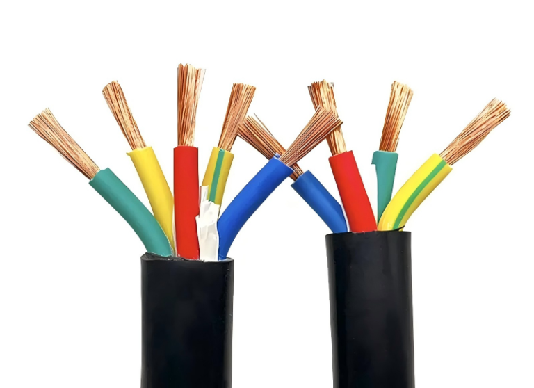
- Colored insulation for phase, neutral, grounding, and control identification.
- Printed jackets showing voltage class, cable type, conductor size, manufacturer, and listing or standard marks where applicable.
- Tracer wires for nonmetallic conduit or direct-buried non-detectable routes.
- Detectable warning tapes placed above the cable route, not directly on the cable.
- Non-detectable warning tapes where mechanical detection is handled another way.
- Cable tiles or protective slabs in higher-risk excavation zones.
- Route markers and as-built drawings tied to fixed site references, not just “near the fence line,” which always seems to move after the next project.
The toughest-looking cable is not always the best underground cable. Over-specified armor can increase bend radius, pulling tension, termination time, gland cost, and heat retention, while giving little benefit inside a clean concrete-encased duct bank. The better choice is the lightest construction that still satisfies the electrical stress, mechanical risk, soil exposure, fire requirement, maintenance strategy, and local code for that particular route.
Sizing and electrical performance
Cable size is selected from the electrical duty and installation conditions, not from distance alone. A long run may force upsizing for voltage drop, but a short run can still need a larger conductor if it carries continuous current in hot soil, shares a duct bank with other loaded cables, or must withstand high fault energy until the breaker or fuse clears.
Start with the load schedule before opening an ampacity table. In plant work, this is where many underground cable mistakes begin: somebody says “it is only 80 meters,” but nobody has locked down the duty cycle, starting current, or future spare capacity.
Define at least these items:
- Continuous load: Current expected for 3 hours or more is usually treated more severely than intermittent load. Lighting, heaters, ventilation fans, wastewater blowers, and EV charging circuits often sit in this category.
- Noncontinuous load: Intermittent pumps, gate operators, sump motors, hoists, and maintenance receptacles may not justify the same operating current assumption, but their starting behavior still matters.
- Motor starting current: Across-the-line motors can pull several times full-load current during acceleration. A cable that passes steady-state ampacity can still cause nuisance trips, slow starts, contactor chatter, or undervoltage at a remote pump station.
- Power factor: Low power factor increases current for the same useful kW. That current heats the conductor and worsens voltage drop.
- Harmonic content: Variable frequency drives, rectifiers, UPS input circuits, LED drivers, and some chargers can distort current. Harmonics add heating that a simple sinusoidal load calculation may miss.
- Future expansion: Spare conduits are cheap compared with trenching twice. Oversizing every conductor is not always the right answer, but ignoring a planned second pump or added charger is usually expensive later.
- Diversity assumptions: Not every load runs at once. Diversity should be documented, not guessed by the buyer under price pressure.
After the load is defined, apply ampacity correction for the actual installation. Conductor metal matters first: copper carries more current at a given size and is easier to terminate in tight gear; aluminum can be commercially attractive on feeders but needs compatible lugs, antioxidant practice where required, and more attention to torque and thermal cycling. Insulation temperature ratings such as 75°C and 90°C are common in underground-rated conductors, but the usable ampacity is limited by termination ratings, code rules, soil conditions, and the complete wiring method.
The heat path is the mechanism that decides whether the table value survives contact with the jobsite. Current creates I²R heat in the conductor. That heat must move through insulation, jacket, air gaps or conduit wall, concrete if present, and then into soil. Dry sandy soil, tightly packed duct banks, and multiple loaded conduits slow that heat transfer, so the same cable can run warmer underground than it would in a ventilated tray. Burial depth, ambient soil temperature, raceway material, conduit fill, and grouping with other cables all change the allowable current.
Underground cable ampacity cannot be selected from conductor size and distance alone.True
Allowable current depends on conductor material, insulation and termination temperature limits, number of current-carrying conductors, raceway or direct-burial method, soil thermal properties, ambient temperature, grouping, and applicable electrical code rules.
Voltage drop is the second sizing check, and on long underground feeders it often governs before ampacity does. Many designers use targets around 3% for branch circuits and 5% total feeder plus branch circuit voltage drop unless the project specification is stricter, but the acceptable limit depends on equipment tolerance and local requirements.
Practical effects are not academic:
- Motors and pumps: Low terminal voltage reduces starting torque. A borehole pump or irrigation pump may start when the line is cool and fail on a hot afternoon with the same breaker and cable.
- Lighting: Voltage drop can cause dimming, driver stress, flicker, or uneven light output across a site.
- Heating equipment: Resistive heaters tolerate voltage drop better electrically, but output falls with voltage, so process heat-up time can change.
- EV charging: Chargers may derate, fault, or extend charge time if voltage at the pedestal sags under load.
- Control circuits: Long low-voltage control runs are sensitive. A contactor coil, solenoid valve, or sensor supply can misbehave even when the power feeder looks acceptable.
Short-circuit performance must be checked as well. The phase conductor, equipment grounding conductor, metallic armor, shield, bonding jumpers, and termination hardware must tolerate the available fault current until the protective device opens. This is not just a cable catalogue issue; it depends on transformer size, upstream impedance, breaker trip settings, fuse curve, conductor length, and grounding system. Medium-voltage and shielded cables add another layer because shield wire size and grounding method affect fault return paths and touch voltage.
Grounding and bonding deserve their own pass during sizing because underground faults are unforgiving. The equipment grounding conductor must be sized to the protective device and fault-clearing requirement. Metallic conduit needs proper bonding across fittings, boxes, and transitions; cable armor must be bonded only as permitted for the system design; shields may be grounded at one end, both ends, or with special bonding depending on voltage class and induced voltage concerns. Ground-fault protection is often what prevents a damaged buried cable from becoming a long, energized metal object in wet soil.
Neutral sizing can also change the conductor set. A balanced three-phase motor feeder may carry little neutral current or no neutral at all. A feeder serving line-to-neutral loads, offices, lighting panels, chargers, or electronic equipment may need a full-size neutral, and nonlinear loads can load the neutral with triplen harmonics. Shared neutrals and service conductors have specific rules that must be checked against the applicable code, not copied from a previous project.
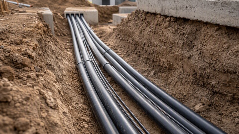
Duct banks are the place where neat drawings can betray the cable. Concrete-encased ducts and closely spaced conduits restrict heat dissipation, especially when several feeders run near rated load. The center ducts in a bank often run hotter than the outer ducts. If the project has high load density, continuous operation, warm climate, or poor soil thermal resistivity, the engineer may need a duct-bank thermal calculation rather than a simple table lookup.
Upsizing is useful, but it is not free. A larger conductor reduces voltage drop and energy loss, and it may provide margin for expansion. It can also exceed lug capacity, increase bend radius, raise pulling tension, require larger conduit, reduce conduit fill allowance, complicate gland selection, and stretch procurement lead time. With large aluminum feeders, the installed cost difference between “one size up” and “now we need different gear” can be ugly.
The preferred size is the smallest compliant conductor system that satisfies ampacity, voltage drop, fault withstand, grounding, installation limits, and future capacity with documented assumptions. That conclusion stops holding when the load profile or installation environment is uncertain; then the next responsible step is not guessing larger cable, but confirming soil conditions, duct arrangement, protective device data, termination limits, and the actual connected load list.
Soil and water exposure
Underground cable should be selected as if it will live in a wet, dirty, mechanically abused environment, not as if it is simply “out of sight.” Direct burial, underground conduit, duct banks, pull boxes, handholes, and manholes are wet or periodically flooded unless the project can prove otherwise with drainage design and site history.
Water is the first assumption I make on buried electrical work. PVC conduit may keep soil off the conductor, but it does not create a dry space; condensation, failed seals, flooded pull boxes, and low-point water traps are routine. A duct bank that looks clean on the drawing can hold water for months after one heavy storm, especially where the route crosses paving and compacted fill. That is why underground conductors need wet-location insulation, and why cable jackets, shields, and terminations must be chosen for long-term moisture exposure rather than short installation convenience.
Soil also affects cable temperature. The cable generates heat under load, and the soil is the heat sink. If the surrounding material cannot move heat away, conductor temperature rises, insulation life falls, and allowable ampacity may need to be reduced.
Common thermal conditions that change the calculation include:
- Dry sand: often poor at carrying heat, especially in arid climates or around heat-producing duct banks.
- Compacted native backfill: usually better than loose fill, but only if moisture content and density are controlled.
- Rocky soil or construction debris: creates air voids and pressure points; both are bad for cable life.
- Concrete encasement: can improve physical protection and provide predictable geometry, but clustered conduits can still run hot if spacing and loading are not checked.
- Mixed native soils along one route: one bad section can set the practical ampacity limit for the whole run.
Chemical exposure is less visible but can be more destructive. Soil pH, salts, fertilizers, industrial runoff, landfill leachate, hydrocarbons, and wastewater can attack polymer jackets, corrode armor, or degrade metallic shields. Coastal soils deserve special attention because chloride-rich moisture can accelerate corrosion, particularly at jacket defects, splice areas, and grounding points. Near fuel storage, vehicle yards, or process drains, do not assume a standard jacket is suitable until the contaminant risk is reviewed against the cable manufacturer’s chemical resistance data.
Corrosion is not only a “metal in wet soil” problem. It can come from several paths:
- Galvanic corrosion: dissimilar metals connected through moist soil or grounding systems.
- Stray current corrosion: nearby DC systems, rail, cathodic protection, or plant grounding faults pushing current through unintended metallic paths.
- Armor and shield corrosion: metallic layers damaged where jackets are cut, abraded, or poorly sealed.
- Bonding design errors: shields and armor bonded in a way that creates circulating currents, heating, or accelerated deterioration.
A buried cable with metallic armor or shielding is only as durable as its jacket integrity, bonding method, and corrosion environment allow. The preferred construction can flip: armor may be justified where excavation damage is likely, but in aggressive wet soil a non-metallic jacketed design with suitable mechanical protection may outlast exposed metallic protection.
Mechanical soil movement is the other nuisance that drawings tend to understate. Rocks, broken concrete, scrap rebar, settlement, frost heave, swelling clay, erosion, root pressure, poor trench compaction, and later excavation all create failure modes that are hard to inspect once the trench is closed. Bedding, warning tape, route markers, spare ducts, and controlled backfill are cheap compared with finding a fault under a finished driveway or production yard.
Biological damage is project-specific. Termites, rodents, insects, microorganisms, and aggressive vegetation are not universal design drivers, but where the site has a history of jacket damage or duct infestation they belong in the cable specification discussion. In some regions, rodent-resistant construction or additional conduit protection is not optional in practice, even if the electrical calculation looks simple.
One small jacket cut can become a long repair problem. Without water-blocking tapes, powders, swelling elements, or sealed conductor screens, water may migrate longitudinally along the cable under capillary action and temperature cycling. The fault might show up far from the original damage point, which is why medium-voltage and critical feeder cables often justify stronger longitudinal water-blocking requirements than short, easily replaceable branch circuits.
Before final cable selection, collect site inputs that describe the route rather than just the load:
- Geotechnical report and soil classification
- Groundwater level and seasonal variation
- Flood history and drainage layout
- Soil thermal resistivity, where ampacity is sensitive
- Soil pH, salinity, and resistivity for corrosion assessment
- Known contamination reports: hydrocarbons, acids, alkalis, fertilizers, industrial wastewater, landfill leachate
- Route survey showing paving, structures, trees, traffic loading, and future excavation zones
- Utility congestion mapping, including existing power, telecom, gas, water, and drainage crossings
The boundary is simple: if the run is short, lightly loaded, accessible, and in benign soil, standard underground-rated products may be enough. Once the route is long, heavily loaded, chemically exposed, flood-prone, or hard to access after installation, the soil report and route survey become procurement documents, not background paperwork.
Burial depth and installation
Use the installation drawing as a construction document, not a suggestion. A good underground cable job is built around verified cover depth, clean trench conditions, controlled pulling, protected transitions, and test records that prove the cable was not damaged before energization.

1. Confirm the required cover depth before digging
Minimum burial depth is set by the applicable electrical code and local authority, then modified by the installation method and site risk. Protected low-voltage landscape circuits may be allowed at roughly 150 mm cover in some jurisdictions, while many residential or light-commercial branch circuits require around 600 mm or more; road crossings, parking areas, agricultural yards, industrial traffic, and medium-voltage work can push the requirement higher.
Check these variables before issuing the trench depth to the crew:
- Jurisdiction and adopted code edition
- Circuit voltage and fault current level
- Branch circuit, feeder, service, control, or communication use
- Direct-buried cable versus conduit or concrete-encased duct bank
- GFCI protection, where code permits reduced cover
- Vehicle loading, paving, landscaping, future excavation risk, and surface use above the route
- Project specifications that exceed minimum code
Do not let the excavator “average out” depth over a long run. Cover is measured from finished grade to the top of the cable, raceway, or protective cover, and low spots after grading are a common reason otherwise decent installations fail inspection.
2. Prepare the trench so the cable is not installed against a knife edge
Mark the route, locate existing utilities, and expose crossings carefully before production trenching starts. In practice, the worst cable damage often comes from ordinary site debris: broken concrete, crushed stone, scrap rebar tie wire, or a sharp shale layer left in the bottom of the trench.
A practical trench checklist includes:
- Utility locating and hand-digging or vacuum excavation at known crossings
- Excavation safety controls for trench depth, soil condition, access, and spoil placement
- Bedding sand, screened soil, or approved fine backfill under and around the cable
- Removal of rocks, construction debris, metal offcuts, and hard clods
- Drainage review where the trench can become a water channel
- Separation from foundations, retaining walls, tree roots, and later fence posts or sign bases
The cable should be supported continuously, not suspended between rocks or pressed against hard points that will concentrate load after backfill settles. That matters more than many crews think, especially with aluminum conductors, armored cable, and larger multi-core cables that do not tolerate point loading gracefully.
3. Control bends, pulling force, and sidewall pressure
Minimum bend radius is not just a neatness rule. Tight bends can deform insulation, open armor, damage metallic shields, or create partial-discharge risk in medium-voltage cable. The allowable radius depends on the exact cable construction, so verify the manufacturer’s data sheet or installation manual, especially for armored, shielded, water-blocked, and medium-voltage products.
During pulling, control the mechanical load as deliberately as the electrical design:
- Use compatible pulling lubricant; some gels attack certain jacket materials or leave residue that complicates terminations.
- Use proper pulling eyes, basket grips, swivels, rollers, and sheaves sized for the cable diameter.
- Monitor winch tension instead of relying on “feel.”
- Account for sidewall pressure at bends, not only straight-line pulling force.
- Avoid dragging cable across trench edges, road plates, conduit mouths, or rough duct openings.
- Keep cable reels correctly oriented and braked; a bird-nested reel at 7 a.m. can ruin the day before the pull begins.
The trade-off is simple: larger sweeps, more pull boxes, and better rollers cost money up front, but they reduce the chance of invisible insulation damage that appears later as nuisance trips, failed insulation resistance tests, or a fault under finished pavement.
4. Build underground conduit and duct banks for pulling and replacement
For conduit systems, the raceway has to be pullable after backfill, not just assembled. Confirm conduit fill, sweep bend count, bend radius, expansion fittings, duct spacing, and transition details before concrete or soil covers the work.
Watch these common failure points:
- Poor solvent cement coverage or rushed joints in PVC conduit
- Misaligned duct banks that pass visual inspection but fail mandrel testing
- Excessive bends between pull points
- Missing pull rope or rope too light for the cable size
- No spare ducts for future circuits or damaged cable replacement
- No sealed transition where conduit enters a building, handhole, pole base, or equipment pad
- Duct spacing too tight for heat dissipation or concrete flow
Mandrel testing and duct cleaning are cheap compared with discovering a crushed conduit after the cable truck is on site. For larger projects, I prefer spare ducts and documented pull points even when the first-cost argument is uncomfortable; underground capacity is expensive to add later.
5. Maintain separation from other buried services
Cable separation is governed by local rules, utility standards, and project specifications. Keep power cables away from gas lines, water pipes, communication cables, steam lines, fuel lines, grounding electrodes, and other heat sources according to the approved layout.
The reason is not only electrical interference. Heat from steam or clustered power circuits reduces ampacity, metallic pipe work can complicate fault return paths, and future maintenance becomes dangerous when services are stacked tightly in one trench. Where crossings are unavoidable, use approved sleeves, vertical separation, mechanical protection, and clear records.
6. Install warning, protection, and location systems
A buried cable that cannot be found is a future outage waiting for a backhoe. Use protection and identification suitable for the site risk:
- Detectable warning tape above the cable or duct line
- Cable tiles, protective boards, or concrete covers where excavation risk is high
- Route markers at direction changes, road crossings, and long straight runs
- Tracer wire for non-metallic conduit systems where required or useful
- Accurate as-built drawings with depth, offsets, splice locations, and crossings
- Geographic information system records for larger plants, campuses, utilities, or municipal networks
Do not accept “roughly along the fence” as an as-built. The person digging there in eight years will not know what the original installer meant.
7. Finish terminations, splices, and pre-energization tests correctly
Underground splices and terminations must be listed or approved for the environment. Use heat-shrink, cold-shrink, resin-filled, gel-filled, or molded systems matched to the cable type, voltage, shield construction, and water exposure. Medium-voltage cable needs trained workmanship for shield cutback, stress control, grounding, and jacket sealing; this is not a place for improvising with tape and confidence.
Before energization, record at least:
- Continuity and phase identification
- Insulation resistance values, using the correct test voltage for the cable and equipment connected
- Sheath or jacket integrity tests where applicable
- Grounding and bonding verification
- Torque values on lugs, connectors, and grounding hardware
- Medium-voltage acceptance testing as specified by the project, utility, or applicable standard
- Splice and termination inspection records, including kit type and installer identification
Testing does not make a damaged cable healthy, but it gives the owner a defensible starting record. If the cable later fails, those baseline results often separate an installation defect from later excavation damage, overload, water ingress, or termination aging.
Failures and field diagnostics
Common underground cable failure modes
Underground cable failures usually start small: a nicked jacket, a damp joint, a hot lug, or a weak insulation spot that only shows up under load or after rain. The trouble is that soil hides the early evidence, so operators often see the symptom at the breaker, starter, VFD, or transformer long before anyone sees the damaged cable.
Typical failure modes worth specifying in inspection and troubleshooting scopes include:
- Insulation breakdown: Aging, overheating, manufacturing defects, poor bending practice, or installation damage can reduce dielectric strength until the conductor faults to ground or phase-to-phase.
- Water treeing: In medium-voltage polymeric insulation, moisture and electric stress can form microscopic tree-like paths. This is slow degradation, not a simple leak, and it often needs specialized testing to detect before failure.
- Jacket puncture: Stones, trench debris, pulling damage, or careless backfill can pierce the outer jacket and let water reach shields, armor, or insulation layers.
- Splice failure: Bad crimping, poor moisture sealing, wrong kit selection, contamination, or rushed heat-shrink work are common. I have seen good cable blamed when the real problem was one ugly joint in a handhole.
- Termination tracking: Dust, moisture, salt, carbon residue, or inadequate creepage distance can create surface leakage paths at switchgear, transformers, or junction boxes.
- Conductor corrosion: Water migration into stranded conductors increases resistance and heat, especially where copper or aluminum is exposed at poorly sealed ends.
- Shield corrosion: Metallic shields, tapes, or wires can corrode after jacket damage, reducing fault-current return capability and making diagnostic readings harder to interpret.
- Overheating: Undersized conductors, overloaded feeders, poor soil thermal conditions, high conduit fill, harmonic load, or loose terminations can push insulation beyond its useful life.
- Mechanical crushing: Settlement, vehicle loading, rocky backfill, or ducts collapsed by construction traffic can deform cable and concentrate stress.
- Rodent damage: More common in ducts, basements, cable trenches, and poorly sealed entries than in deep compacted soil, but still a legitimate failure source.
- Excavation strikes: The most sudden and least mysterious failure mode. A scrape from a bucket tooth may not trip immediately, which makes it dangerous.
Symptoms that should trigger investigation
Do not treat repeat trips as a normal nuisance. Repeatedly resetting a tripping underground circuit can turn a small insulation defect into carbon tracking, a cable fire risk, damaged connected equipment, or a much larger fault. That is especially true where the breaker trips after rain, during motor starting, or only after the load has warmed up.
Watch for:
- Nuisance tripping with no clear load change
- Low voltage at the far end of the run
- Flickering lights on underground-fed circuits
- Motors that hesitate, stall, or trip overloads during starting
- Intermittent faults during rain, snowmelt, irrigation, or high humidity
- Warm terminations, lugs, elbows, or junction boxes
- Burning smell near enclosures, pull boxes, or switchgear
- Unexplained ground-fault indications on protection relays, RCDs, GFCIs, or monitoring systems
The mechanism is usually simple: moisture lowers insulation resistance, heat raises conductor resistance and accelerates insulation aging, and poor connections create local temperature rise. The trade-off is whether to keep running while monitoring or shut down and test. On a non-critical lighting circuit, scheduled diagnosis may be acceptable; on a pump feeder, process line, mine circuit, or hospital utility feed, waiting can cost far more than a controlled outage.
Field testing methods
Testing should match cable voltage class, age, insulation type, and the question being asked. A maintenance electrician with a megohmmeter can find some problems, but not every underground defect is visible through one insulation resistance number.
Common diagnostic tools include:
| Test method | What it helps identify | Practical caution |
|---|---|---|
| Insulation resistance testing | Gross insulation weakness, moisture ingress, phase-to-ground leakage | Test voltage and duration must suit the cable and connected equipment; disconnect sensitive electronics first. |
| Very low frequency testing | Withstand capability on many medium-voltage cable systems | Useful, but it is a stress test; aged cable may fail during the test if it is already near breakdown. |
| Tan delta testing | Overall insulation condition and water-tree-related aging trends | Best compared against baselines or similar phases, not treated as a magic pass/fail number. |
| Partial discharge testing | Voids, sharp defects, poor terminations, accessory problems | Interpretation needs experienced personnel and clean test setup. |
| Time-domain reflectometry | Approximate fault distance, open circuits, impedance changes | Accuracy depends on correct velocity factor, cable construction, and fault type. |
| Sheath testing | Jacket damage and metallic screen/sheath integrity | Especially valuable where water entry or shield corrosion is suspected. |
| Continuity testing | Open conductors, broken shields, wrong connections | Basic, but still catches plenty of installation and repair errors. |
| Thermal inspection | Hot lugs, overloaded terminations, unbalanced phases | Limited to accessible ends and equipment; it will not see a buried hot spot directly. |
This guidance stops holding when the cable is part of a utility-owned network, hazardous-area installation, or high-energy medium-voltage system with strict switching and test procedures. In those cases, the test plan belongs in the hands of qualified personnel working from the current equipment manuals, protection settings, and site safety rules.
Records that make diagnostics faster
Good records save hours when a fault happens at 2 a.m. The useful files are not fancy; they are the ones a technician can trust while standing beside a locked feeder cabinet in the rain.
Keep:
- Route maps showing actual cable paths, not just design intent
- As-built drawings with depths, crossings, ducts, pull boxes, and spare conduits
- Installation photos before backfill, preferably with landmarks or measured references
- Joint, splice, and termination locations
- Cable drum records, batch references, lengths, and direction of pull
- Commissioning reports with insulation resistance, sheath, VLF, tan delta, or other baseline values
- Repair history, including fault cause and exact repair location
Repair decision after a fault
A localized splice repair makes sense when the cable is relatively young, the fault cause is known, the damaged point is accessible, and the remaining cable tests clean. Cable section replacement is better when damage extends beyond one point, water has migrated, or the route includes a bad duct bank section.
Full route replacement is painful but often justified when the cable is old, records are poor, insulation tests show system-wide deterioration, or repeated failures have already consumed maintenance time. A temporary bypass can keep production alive, but it must be treated as an engineered temporary supply with protection, mechanical guarding, load rating, and removal date controlled—not as a cable lying across the yard under a pallet.
Standards and purchasing documents
A good underground cable purchase specification should name the governing standard first, then define the cable construction, test evidence, packaging, and delivery conditions tightly enough that two suppliers quote the same product. If the buyer only writes “underground electrical wire, 600 V, copper,” procurement will get non-comparable offers and the cheapest one may fail on wet-location rating, jacket durability, voltage drop, or documentation.
Start with the project jurisdiction and end-user rulebook. For North American building work, that may mean NEC installation rules with UL or CSA listed cable types and local inspection requirements. Utility, industrial, and export projects may reference IEC 60502 for power cables, IEC 60228 for conductor classes, IEC 60332 for flame behavior, ICEA and IEEE documents for medium-voltage cable design and testing, or BS, EN, and local utility specifications. The same cable can be technically sound and still be commercially unusable if the certificate set does not match the authority having jurisdiction or the owner’s approved vendor list.
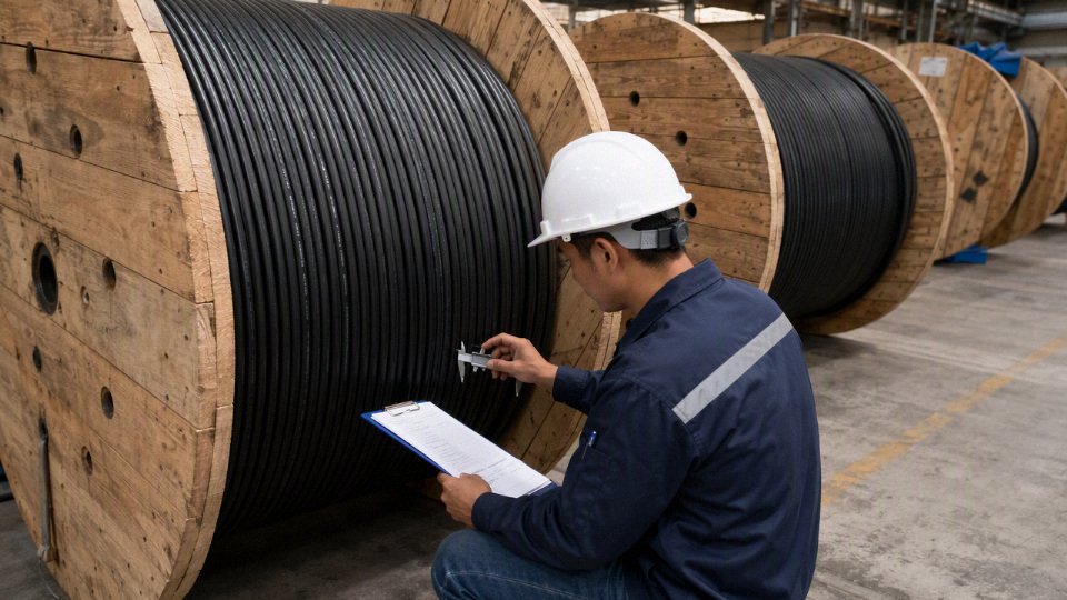
For the cable itself, put the construction fields in the request for quotation, not in an email side note:
- Voltage rating: for example, low-voltage building circuits, 0.6/1 kV distribution, or medium-voltage feeders as applicable.
- Conductor material and size: copper or aluminum, nominal cross-section or AWG/kcmil, and whether compacted or non-compacted.
- Conductor class: solid, stranded, flexible, or IEC class requirement; this affects pulling, termination, and bend behavior.
- Insulation compound: PVC, XLPE, EPR, or other specified material, with temperature rating and wet-location suitability.
- Jacket compound: PVC, PE, LSZH, CPE, or project-specific material selected for soil, sunlight exposure, oil, or chemical contact.
- Shield and armor: metallic screen, concentric neutral, tape shield, wire shield, steel wire armor, aluminum wire armor, or non-armored construction.
- Water blocking: longitudinal water-blocking tape, powder, yarn, or radial moisture barrier where the service risk justifies it.
- Flame rating and color coding: especially for risers, tray sections, tunnels, substations, and mixed-voltage sites.
- Manufacturing length tolerance and drum packaging: state acceptable tolerance, reel type, reel marking, and whether cut lengths are permitted.
Environmental and installation fields deserve equal attention. State whether the cable must be listed or suitable for direct burial, wet locations, underground conduit, outdoor storage, ultraviolet exposure, oil exposure, or chemically aggressive soil. Include minimum installation temperature, expected operating temperature, maximum pulling tension, minimum bend radius, sidewall pressure limits where relevant, and whether the cable will be pulled through long duct banks with several sweeps. These values must come from the manufacturer’s data and the applicable standard, not from a contractor’s habit of “pulling until it moves.”
Compliance paperwork should be specified before the purchase order is released. Typical requirements include:
- Type test reports for the relevant cable design and standard.
- Routine test reports for the manufactured lot.
- Factory acceptance test records when witnessed or project-required.
- Certificates of conformity.
- Material declarations, including restricted-substance statements where needed.
- Quality management certificates.
- Traceability records tying conductor, insulation, jacket, test results, and drum number to the shipped cable.
Commercial documents matter because underground cable is expensive to rework once the trench is open. Confirm delivery schedule, project phasing, spare length, reel dimensions and weight, unloading method, shipping route, storage requirements, marking language, warranty expectations, and after-sales technical support. I like to see reel weights checked against the site’s forklift or crane capacity; that small detail prevents a surprising amount of yard improvisation.
Supplier evaluation should cover manufacturing capacity, export experience, engineering response time, customization ability, quality control process, in-house test equipment, reference projects, and long-term supply reliability. A vertically integrated manufacturer such as Shandong Jinda Special Cable Group, with R&D, production, sales, technical support, and after-sales service under one system, is better positioned to align underground cable construction with international project requirements than a trader who only forwards catalogue sheets. The buyer still has to verify the proposed standard, certificates, and test plan against the actual project specification before release.
Frequently asked questions
Can regular indoor electrical wire be buried underground?
No. Ordinary indoor building wire is not acceptable for burial unless it is part of an approved wiring method and the conductor or cable is marked for the environment. Indoor NM cable, often called Romex in the trade, is not made for wet soil and should not be buried directly or pulled through underground conduit as a substitute for wet-location cable.
Indoor NM cable is suitable for direct underground burial if it is installed inside PVC conduit.False
Underground conduit is normally considered a wet location. The cable or conductors still need markings and construction suitable for that environment.
Is THHN wire allowed underground?
THHN by itself is not enough for underground conduit. Many single conductors sold for building work are dual-marked THHN/THWN-2; in that case, the THWN-2 wet-location rating is the relevant marking. Check the print legend on the insulation, not just the carton label.
What wire is best for running power to a shed?
It depends on the shed load, run length, voltage, local code, burial method, and whether the shed needs a subpanel, grounding electrode, or disconnect. For small residential jobs, UF-B direct-burial cable or individual wet-location conductors in PVC conduit are common where permitted. Longer runs may need upsizing for voltage drop, even when ampacity looks acceptable.
Does underground wire have to be in conduit?
Not always. Listed direct-burial cable may be installed without continuous conduit if the code and site conditions allow it. In practice, conduit or rigid protection is often used at risers, building exits, driveway crossings, wall penetrations, and places where a future shovel, auger, or skid-steer bucket is likely to find the cable.
What size wire is needed for underground service?
Service conductors are sized from calculated load, voltage, conductor material, insulation rating, installation conditions, service equipment, utility rules, and code requirements. Distance matters mainly through voltage drop and fault-current performance. A 200 A underground service is not sized the same way as a 40 A feeder to a pump house.
Is aluminum underground cable safe?
Yes, when it is correctly sized, listed for the application, protected from moisture entry, and terminated with connectors rated for aluminum. Most problems I have seen came from poor terminations: wrong lugs, no oxide inhibitor where required, loose torque, or copper-only devices used because someone was short on parts.
How long does underground cable last?
Service life is driven less by calendar age than by insulation quality, soil chemistry, moisture control, loading, splices, thermal cycling, and mechanical damage. A well-installed underground feeder can run for decades; a nicked jacket in wet clay with a marginal splice can fail in a few seasons.
Can underground cable be repaired?
Yes, if the repair uses an approved underground splice system matched to the cable type, voltage, conductor material, and wet-location exposure. For one clean excavation damage, a proper splice may be sensible. For repeated faults, water-tracked insulation, or old unknown cable, replacement is usually the safer commercial decision.
Verify your cable specification
Use this final check before the purchase order is released or the trench is closed:
- Confirm voltage, phase, load, duty cycle, and protective device size. A small lighting circuit, a 400 A service feeder, a pump circuit with hard starts, and a solar collection run do not want the same cable even if they share the same trench length.
- Choose the installation method deliberately: listed direct-burial cable in prepared soil, or wet-location conductors/cable in underground conduit. Treat buried conduit as wet unless the applicable code and site design prove otherwise.
- Verify the markings. Look for the required wet-location, direct-burial, voltage, conductor material, insulation, jacket, shield, armor, and standard markings. “PVC cable,” “outdoor wire,” or “underground type” is not a procurement specification.
- Calculate conductor size from ampacity and voltage drop. Long underground runs often fail commercially before they fail electrically: nuisance trips, dimming, motor heating, poor inverter performance, or owner complaints after energization.
- Check soil and mechanical risks. Wet clay, rock backfill, contaminated ground, road crossings, termite exposure, high soil temperature, grouped circuits, and poor drainage can change the cable construction or the required derating.
- Confirm burial depth, warning tape, separation, bends, pull boxes, and termination conditions. The cable is only as reliable as the route it is installed in.
- Specify documents before shipment: datasheet, applicable standard, construction drawing if required, factory test record, certification documents, packing details, drum lengths, and traceability marking.
The expensive mistakes are familiar: indoor building wire pulled underground, conduit assumed to be dry, voltage drop ignored because ampacity “passed,” soil thermal conditions guessed, and vague cable descriptions accepted because the price looked clean. The right underground electrical wire is not one universal product; it is the cable or conductor system whose listing, construction, ampacity, protection, and documentation match the buried environment.
For a practical recommendation or quotation from Jinda, send the project drawings or route sketch, voltage and load data, route length, burial method, soil or water conditions, required standards or certifications, drum length preference, delivery schedule, and any site photos. Jinda can support residential-scale supply, commercial projects, industrial plants, utilities, renewable energy sites, and international bulk cable orders with engineering review, manufacturing, technical support, and after-sales service.